US20020184888A1 - Connection for a two-part CMC chamber - Google Patents
Connection for a two-part CMC chamber Download PDFInfo
- Publication number
- US20020184888A1 US20020184888A1 US10/161,662 US16166202A US2002184888A1 US 20020184888 A1 US20020184888 A1 US 20020184888A1 US 16166202 A US16166202 A US 16166202A US 2002184888 A1 US2002184888 A1 US 2002184888A1
- Authority
- US
- United States
- Prior art keywords
- metal
- combustion chamber
- composite material
- nozzle
- tabs
- Prior art date
- Legal status (The legal status is an assumption and is not a legal conclusion. Google has not performed a legal analysis and makes no representation as to the accuracy of the status listed.)
- Granted
Links
- 239000002184 metal Substances 0.000 claims abstract description 50
- 229910052751 metal Inorganic materials 0.000 claims abstract description 50
- 238000002485 combustion reaction Methods 0.000 claims abstract description 42
- 239000002131 composite material Substances 0.000 claims abstract description 28
- 238000007789 sealing Methods 0.000 claims abstract description 14
- 239000007769 metal material Substances 0.000 claims abstract description 9
- 239000000446 fuel Substances 0.000 claims abstract description 5
- 238000005219 brazing Methods 0.000 claims description 4
- 238000002788 crimping Methods 0.000 claims description 4
- 238000003466 welding Methods 0.000 claims description 4
- 239000000919 ceramic Substances 0.000 description 5
- 238000002347 injection Methods 0.000 description 5
- 239000007924 injection Substances 0.000 description 5
- 239000011153 ceramic matrix composite Substances 0.000 description 4
- 238000011144 upstream manufacturing Methods 0.000 description 4
- 239000000463 material Substances 0.000 description 3
- 239000007800 oxidant agent Substances 0.000 description 3
- 238000006073 displacement reaction Methods 0.000 description 2
- OKTJSMMVPCPJKN-UHFFFAOYSA-N Carbon Chemical compound [C] OKTJSMMVPCPJKN-UHFFFAOYSA-N 0.000 description 1
- 229910052799 carbon Inorganic materials 0.000 description 1
- 238000001816 cooling Methods 0.000 description 1
- 230000007797 corrosion Effects 0.000 description 1
- 238000005260 corrosion Methods 0.000 description 1
- 238000009792 diffusion process Methods 0.000 description 1
- 150000002739 metals Chemical class 0.000 description 1
- 230000000284 resting effect Effects 0.000 description 1
Images


Classifications
-
- F—MECHANICAL ENGINEERING; LIGHTING; HEATING; WEAPONS; BLASTING
- F23—COMBUSTION APPARATUS; COMBUSTION PROCESSES
- F23R—GENERATING COMBUSTION PRODUCTS OF HIGH PRESSURE OR HIGH VELOCITY, e.g. GAS-TURBINE COMBUSTION CHAMBERS
- F23R3/00—Continuous combustion chambers using liquid or gaseous fuel
- F23R3/42—Continuous combustion chambers using liquid or gaseous fuel characterised by the arrangement or form of the flame tubes or combustion chambers
- F23R3/60—Support structures; Attaching or mounting means
-
- F—MECHANICAL ENGINEERING; LIGHTING; HEATING; WEAPONS; BLASTING
- F23—COMBUSTION APPARATUS; COMBUSTION PROCESSES
- F23R—GENERATING COMBUSTION PRODUCTS OF HIGH PRESSURE OR HIGH VELOCITY, e.g. GAS-TURBINE COMBUSTION CHAMBERS
- F23R3/00—Continuous combustion chambers using liquid or gaseous fuel
- F23R3/007—Continuous combustion chambers using liquid or gaseous fuel constructed mainly of ceramic components
-
- F—MECHANICAL ENGINEERING; LIGHTING; HEATING; WEAPONS; BLASTING
- F05—INDEXING SCHEMES RELATING TO ENGINES OR PUMPS IN VARIOUS SUBCLASSES OF CLASSES F01-F04
- F05B—INDEXING SCHEME RELATING TO WIND, SPRING, WEIGHT, INERTIA OR LIKE MOTORS, TO MACHINES OR ENGINES FOR LIQUIDS COVERED BY SUBCLASSES F03B, F03D AND F03G
- F05B2230/00—Manufacture
- F05B2230/60—Assembly methods
- F05B2230/604—Assembly methods using positioning or alignment devices for aligning or centering, e.g. pins
- F05B2230/606—Assembly methods using positioning or alignment devices for aligning or centering, e.g. pins using maintaining alignment while permitting differential dilatation
Definitions
- the present invention relates to the specific field of turbomachines and it relates more particularly to the problem posed by assembling a combustion chamber made of a composite material of the ceramic matrix composite (CMC) type in the metal casing of a turbomachine.
- CMC ceramic matrix composite
- the high pressure turbine in particular its inlet nozzle (HPT nozzle), the combustion chamber, and the casing (or shell) of said chamber are all made out of the same material, generally a metal.
- HPT nozzle inlet nozzle
- the combustion chamber in particular its combustion chamber
- the casing (or shell) of said chamber are all made out of the same material, generally a metal.
- a metal chamber turns out to be completely unsuitable from a thermal point of view and it is necessary to make use of a chamber that is based on high temperature composite materials of the CMC type.
- difficulties of implementation and materials costs mean that such materials are generally restricted to being used for the composite chamber itself, with the high pressure turbine inlet nozzle and the casing then still being made more conventionally out of metal materials.
- metals and composites have coefficients of thermal expansion that are very different. This gives rise to particularly awkward problems of connection between the casing and the combustion chamber and of sealing at the nozzle at the inlet to the high pressure turbine.
- the present invention mitigates those drawbacks by proposing a mounting for the combustion chamber in the casing with the ability to absorb the displacements induced by the various coefficients of expansion of those parts.
- a turbomachine comprising a shell of metal material containing in a gas flow direction F: a fuel injector assembly, a composite material combustion chamber having a longitudinal axis, and a metal nozzle forming the fixed blade inlet stage of a high pressure turbine, wherein said composite material combustion chamber is held in position inside said metal shell by a plurality of flexible metal tabs having first and second ends, said first ends being interconnected by a flange-forming metal ring fixed to said metal shell by first fixing means, and each of said second ends being fixed by second fixing means both to said composite material combustion chamber and to one end of a composite material wall whose other end forms a bearing plane for a sealing element secured to said nozzle and providing sealing for the stream of gas between said combustion chamber and said nozzle, the flexibility of said metal fixing tabs allowing expansion to take place freely in a radial direction at high temperatures between said composite material combustion chamber and said metal shell.
- the first and second fixing means are preferably constituted by a plurality of bolts. Nevertheless, the second fixing means could also be constituted by crimping elements.
- said sealing element is of the circular “spring blade” gasket type. It can have a plurality of calibrated leakage orifices.
- the metal shell is made up of two portions
- said metal ring interconnecting said first ends of said flexible metal tabs is mounted between connecting flanges of said two portions.
- said metal ring can be fixed directly to said annular shell by conventional fixing means.
- said first ends of the fixing tabs can either be fixed by brazing (or welding) to said flange-forming metal ring, or else they can be formed integrally with said metal ring.
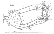
- FIG. 1 is a diagrammatic axial half-section of a central zone of a turbomachine in a first embodiment of the invention
- FIGS. 1A and 1B are respectively a perspective view and a section view showing details of elements in FIG. 1;
- FIG. 2 is a view on a larger scale showing a portion of FIG. 1 in a first alternative connection configuration
- FIG. 3 is an enlarged view of another portion of FIG. 1 in a second alternative connection configuration.
- FIG. 1 is an axial half-section view of a central portion of a turbojet or a turboprop (with the term “turbomachine” being used generically in the description below) and comprising in a first embodiment:
- an outer annular shell made up of two portions 12 a and 12 b of metal material, having a longitudinal axis 10 ;
- an inner annular shell (or inner casing) that is coaxial therewith and likewise comprises two portions 14 a and 14 b , also made of metal material;
- annular space 16 extending between the two shells 12 a , 12 b and 14 a , 14 b for receiving compressed oxidizer, generally air, coming from an upstream compressor (not shown) of the turbomachine via an annular diffuser duct 18 (having a diffuser screen 18 a ) defining a general flow F of gas.
- this space 16 comprises firstly an injection assembly formed by a plurality of injection systems 20 that are regularly distributed around the duct 18 , each comprising a fuel injection nozzle 22 fixed to an upstream portion 12 a of the outer annular shell 12 (in order to simplify the drawings, the mixer and the deflector associated with each injection nozzle are omitted), followed by a combustion chamber 24 of high temperature composite material, e.g. of the CMC type or of some other type (e.g.
- the nozzle is fixed to the downstream portion 14 b of the inner annular shell of the turbomachine by first removable fixing means preferably constituted by a plurality of bolts 50 , while resting on support means 49 secured to the outer annular shell of the turbomachine.
- Through orifices 54 , 56 formed in the outer and inner metal platforms 46 and 48 of the nozzle 42 are also provided to cool the fixed blades 46 of this nozzle at the inlet to the rotor of the high pressure turbine using compressed oxidizer available at the outlet from the diffusion duct 18 and flowing in two flows F 1 and F 2 on either side of the combustion chamber 24 .
- the combustion chamber 24 has a coefficient of thermal expansion that is very different from that of the other parts forming the turbomachine, since they are made of metal.
- the combustion chamber 24 is held securely in position within its shell by a plurality of flexible tabs 58 , 60 regularly distributed around the combustion chamber between the inner and outer annular shells.
- a first fraction of these fixing tabs (see the tab referenced 58 ) is mounted between the outer annular shell 12 a , 12 b and the outer axial wall 26 of the combustion chamber, while a second fraction (like the tab 60 ) is mounted between the inner annular shell 14 a , 14 b and the inner axial wall 28 of the combustion chamber.
- the number of tabs can be a number that is equal to the number injection nozzles or to a multiple of said number.
- Each flexible fixing tab of metal material can be substantially triangular in shape as shown in FIG. 1A or it can be constituted by a single blade (not shown and of optionally constant width), and it is welded or brazed at a first end 62 ; 64 to a metal ring 66 a , 66 b forming a flange and fixed securely by first fixing means 52 ; 68 to one or the other of the inner and outer metal annular shells (depending on where it is located).
- This fixing by means of a flange is intended to make it easier to hold these tabs on the metal shells.
- these tabs and the metal ring together form a single one-piece metal part.
- each tab is fixed via second fixing means 74 , 76 firstly to a downstream end 88 ; 90 of the outer and inner axial walls 26 and 28 of the ceramic composite material combustion chamber, and secondly to one end of a ceramic composite wall 78 a ; 78 b lying in line with each of the outer and inner axial walls and forming a kind of second portion of the chamber.
- This second portion has an opposite end in the form of a bearing plane for a sealing element secured to the nozzle and providing sealing for the stream of gas between the combustion chamber 24 and the nozzle 42 .
- connection between the second ends of the tabs 70 , 72 and the downstream ends of the walls of the combustion chamber and the first ends of the ceramic composite walls forming the second portion of the combustion chamber is implemented merely by bolting, preferably using bolts of the captive nut type so as to facilitate assembly and disassembly and also to limit the size of the tabs.
- the metal ring 66 a , 66 b interconnecting the first ends 62 , 64 of the tabs is preferably clamped between the existing connection flanges between the upstream and downstream portions 12 a & 14 a and 12 b & 14 b of the inner and outer annular shells and held securely by the first fixing means 52 , 68 which are preferably likewise of the bolt type.
- first fixing means 52 , 68 which are preferably likewise of the bolt type.
- ceramic composite material washers 74 a ; 76 a are provided to enable the flat headed screws of the bolts forming the second fixing means 74 ; 76 to be “embedded”.
- the stream of gas between the combustion chamber 24 and the nozzle 42 is sealed by a circular “spring blade” gasket 80 , 82 mounted in a groove 84 , 86 of each of the outer and inner platforms 46 and 48 of the nozzle and which bear directly against the second end portion of the ceramic composite wall 78 a ; 78 b forming a bearing plane for said circular sealing gasket.
- the gasket is pressed against said second end of the composite wall by means of a resilient element of the blade spring type 92 , 94 fixed to the nozzle.
- the gas flows between the combustion chamber and the turbine are sealed firstly by an omega type circular sealing gasket 96 mounted in a circular groove 98 of a flange of the inner annular shell 14 in direct contact with the inner circular platform 48 of the nozzle, and secondly by another circular spring blade gasket 100 mounted in a circular groove 102 of the outer circular platform of the nozzle 46 and having one end in direct contact with a circular projection 104 on the downstream portion 12 b of the outer annular shell.
- FIG. 1B shows a first variant of the preceding embodiment in which the tabs at the downstream end 90 of the combustion chamber 24 are fixed (only the tab 60 is shown) by a crimped connection, the bolts 76 being replaced by crimping elements 76 b .
- the flange-forming metal ring 66 a interconnecting the first ends 62 of the fixing tabs 58 of the outer axial wall of the combustion chamber 26 by brazing (or welding) is no longer mounted between flanges but is itself brazed (or welded) to a centered keying element 106 bearing against the outer annular shell 12 .
- the flange-forming metal ring 66 b interconnecting the first ends 64 of the fixing tabs 60 of the inner axial wall of the combustion chamber 28 by brazing (or welding) is no longer mounted between flanges but is merely fixed directly to the inner annular shell 14 by conventional fixing means 108 , e.g. of the bolt type.
- the flexibility of the fixing tabs makes it possible to accommodate the thermal expansion difference that appears at high temperatures between the composite material combustion chamber and the metal annular shells, while continuing to hold and position the combustion chamber.
Landscapes
- Engineering & Computer Science (AREA)
- Chemical & Material Sciences (AREA)
- Combustion & Propulsion (AREA)
- Mechanical Engineering (AREA)
- General Engineering & Computer Science (AREA)
- Ceramic Engineering (AREA)
- Turbine Rotor Nozzle Sealing (AREA)
- Chimneys And Flues (AREA)
- Gasket Seals (AREA)
Abstract
Description
- The present invention relates to the specific field of turbomachines and it relates more particularly to the problem posed by assembling a combustion chamber made of a composite material of the ceramic matrix composite (CMC) type in the metal casing of a turbomachine.
- Conventionally, in a turbojet or a turboprop, the high pressure turbine, in particular its inlet nozzle (HPT nozzle), the combustion chamber, and the casing (or shell) of said chamber are all made out of the same material, generally a metal. Nevertheless, under certain particular conditions of use implementing particularly high combustion temperatures, a metal chamber turns out to be completely unsuitable from a thermal point of view and it is necessary to make use of a chamber that is based on high temperature composite materials of the CMC type. However, difficulties of implementation and materials costs mean that such materials are generally restricted to being used for the composite chamber itself, with the high pressure turbine inlet nozzle and the casing then still being made more conventionally out of metal materials. Unfortunately, metals and composites have coefficients of thermal expansion that are very different. This gives rise to particularly awkward problems of connection between the casing and the combustion chamber and of sealing at the nozzle at the inlet to the high pressure turbine.
- The present invention mitigates those drawbacks by proposing a mounting for the combustion chamber in the casing with the ability to absorb the displacements induced by the various coefficients of expansion of those parts.
- This object is achieved by a turbomachine comprising a shell of metal material containing in a gas flow direction F: a fuel injector assembly, a composite material combustion chamber having a longitudinal axis, and a metal nozzle forming the fixed blade inlet stage of a high pressure turbine, wherein said composite material combustion chamber is held in position inside said metal shell by a plurality of flexible metal tabs having first and second ends, said first ends being interconnected by a flange-forming metal ring fixed to said metal shell by first fixing means, and each of said second ends being fixed by second fixing means both to said composite material combustion chamber and to one end of a composite material wall whose other end forms a bearing plane for a sealing element secured to said nozzle and providing sealing for the stream of gas between said combustion chamber and said nozzle, the flexibility of said metal fixing tabs allowing expansion to take place freely in a radial direction at high temperatures between said composite material combustion chamber and said metal shell.
- With this particular structure for the fixed connection, the various kinds of wear due to contact corrosion in prior art systems can be avoided. The use of a wall made of composite material placed in line with the combustion chamber to provide sealing of the stream also makes it possible to reconstitute the initial structure of the chamber. In addition, the presence of flexible metal tabs replacing the traditional flanges gives rise to a saving in mass that is particularly appreciable. In addition to being flexible, these tabs make it easy to accommodate the expansion difference that appears at high temperatures between metal parts and composite parts (by accommodating the displacements due to expansion) while still ensuring that the combustion chamber is properly held and well centered in the shell.
- The first and second fixing means are preferably constituted by a plurality of bolts. Nevertheless, the second fixing means could also be constituted by crimping elements. Advantageously, said sealing element is of the circular “spring blade” gasket type. It can have a plurality of calibrated leakage orifices.
- In an advantageous embodiment in which the metal shell is made up of two portions, said metal ring interconnecting said first ends of said flexible metal tabs is mounted between connecting flanges of said two portions. In an alternative embodiment, said metal ring can be fixed directly to said annular shell by conventional fixing means.
- Depending on the intended embodiment, said first ends of the fixing tabs can either be fixed by brazing (or welding) to said flange-forming metal ring, or else they can be formed integrally with said metal ring.
- The characteristics and advantages of the present invention appear better from the following description made by way of non-limiting indication and with reference to the accompanying drawings, in which:
- FIG. 1 is a diagrammatic axial half-section of a central zone of a turbomachine in a first embodiment of the invention;
- FIGS. 1A and 1B are respectively a perspective view and a section view showing details of elements in FIG. 1;
- FIG. 2 is a view on a larger scale showing a portion of FIG. 1 in a first alternative connection configuration; and
- FIG. 3 is an enlarged view of another portion of FIG. 1 in a second alternative connection configuration.
- FIG. 1 is an axial half-section view of a central portion of a turbojet or a turboprop (with the term “turbomachine” being used generically in the description below) and comprising in a first embodiment:
- an outer annular shell (or outer casing) made up of two
portions 12 a and 12 b of metal material, having alongitudinal axis 10; - an inner annular shell (or inner casing) that is coaxial therewith and likewise comprises two
portions - an
annular space 16 extending between the twoshells - In the gas flow direction, this
space 16 comprises firstly an injection assembly formed by a plurality ofinjection systems 20 that are regularly distributed around theduct 18, each comprising afuel injection nozzle 22 fixed to an upstream portion 12 a of the outer annular shell 12 (in order to simplify the drawings, the mixer and the deflector associated with each injection nozzle are omitted), followed by acombustion chamber 24 of high temperature composite material, e.g. of the CMC type or of some other type (e.g. carbon), formed by an outer axially-extendingside wall 26 and an inner axially-extendingside wall 28, both disposed coaxially about theaxis 10, and a transversely-extendingend wall 30 of said combustion chamber and which hasmargins upstream ends said side walls chamber end wall 30 being provided withorifices 40 specifically to enable fuel to be injected together with a fraction of the oxidizer into thecombustion chamber 24, and finally anannular nozzle 42 of metal material forming an inlet stage of a high pressure turbine (not shown) and conventionally comprising a plurality offixed blades 44 mounted between an outercircular platform 46 and an innercircular platform 48. - The nozzle is fixed to the
downstream portion 14 b of the inner annular shell of the turbomachine by first removable fixing means preferably constituted by a plurality ofbolts 50, while resting on support means 49 secured to the outer annular shell of the turbomachine. - Through
orifices inner metal platforms nozzle 42 are also provided to cool thefixed blades 46 of this nozzle at the inlet to the rotor of the high pressure turbine using compressed oxidizer available at the outlet from thediffusion duct 18 and flowing in two flows F1 and F2 on either side of thecombustion chamber 24. - The
combustion chamber 24 has a coefficient of thermal expansion that is very different from that of the other parts forming the turbomachine, since they are made of metal. In accordance with the invention, thecombustion chamber 24 is held securely in position within its shell by a plurality offlexible tabs annular shell 12 a, 12 b and the outeraxial wall 26 of the combustion chamber, while a second fraction (like the tab 60) is mounted between the innerannular shell axial wall 28 of the combustion chamber. By way of example, the number of tabs can be a number that is equal to the number injection nozzles or to a multiple of said number. - Each flexible fixing tab of metal material can be substantially triangular in shape as shown in FIG. 1A or it can be constituted by a single blade (not shown and of optionally constant width), and it is welded or brazed at a
first end 62; 64 to ametal ring - At a
second end 70; 72, each tab is fixed via second fixing means 74, 76 firstly to adownstream end 88; 90 of the outer and inneraxial walls composite wall 78 a; 78 b lying in line with each of the outer and inner axial walls and forming a kind of second portion of the chamber. This second portion has an opposite end in the form of a bearing plane for a sealing element secured to the nozzle and providing sealing for the stream of gas between thecombustion chamber 24 and thenozzle 42. - In the embodiment of the invention shown in FIG. 1, the connection between the second ends of the
tabs metal ring first ends composite material washers 74 a; 76 a are provided to enable the flat headed screws of the bolts forming the second fixing means 74; 76 to be “embedded”. - The stream of gas between the
combustion chamber 24 and thenozzle 42 is sealed by a circular “spring blade”gasket groove inner platforms composite wall 78 a; 78 b forming a bearing plane for said circular sealing gasket. The gasket is pressed against said second end of the composite wall by means of a resilient element of theblade spring type combustion chamber 24 and thenozzle 42. Nevertheless, in order to cool the dead zone created beneath thenozzle 46 by the composite wall, calibrated leakage orifices 110 (shown only in FIG. 1B) are advantageously provided through thegaskets - The gas flows between the combustion chamber and the turbine are sealed firstly by an omega type
circular sealing gasket 96 mounted in acircular groove 98 of a flange of the innerannular shell 14 in direct contact with the innercircular platform 48 of the nozzle, and secondly by another circularspring blade gasket 100 mounted in acircular groove 102 of the outer circular platform of thenozzle 46 and having one end in direct contact with acircular projection 104 on thedownstream portion 12 b of the outer annular shell. - FIG. 1B shows a first variant of the preceding embodiment in which the tabs at the
downstream end 90 of thecombustion chamber 24 are fixed (only thetab 60 is shown) by a crimped connection, thebolts 76 being replaced bycrimping elements 76 b. With this configuration, it is possible to perform cooling through the crimping element so there is no need to provide calibrated orifices through thespring blade gaskets - In the variant shown in FIG. 2, the flange-forming
metal ring 66 a interconnecting thefirst ends 62 of thefixing tabs 58 of the outer axial wall of thecombustion chamber 26 by brazing (or welding) is no longer mounted between flanges but is itself brazed (or welded) to acentered keying element 106 bearing against the outerannular shell 12. - In another variant shown in FIG. 3, the flange-forming
metal ring 66 b interconnecting thefirst ends 64 of thefixing tabs 60 of the inner axial wall of thecombustion chamber 28 by brazing (or welding) is no longer mounted between flanges but is merely fixed directly to the innerannular shell 14 byconventional fixing means 108, e.g. of the bolt type. - In all of the above-described configurations, the flexibility of the fixing tabs makes it possible to accommodate the thermal expansion difference that appears at high temperatures between the composite material combustion chamber and the metal annular shells, while continuing to hold and position the combustion chamber.
Claims (9)
Applications Claiming Priority (2)
| Application Number | Priority Date | Filing Date | Title |
|---|---|---|---|
| FR0107372 | 2001-06-06 | ||
| FR0107372A FR2825785B1 (en) | 2001-06-06 | 2001-06-06 | TWO-PIECE TURBOMACHINE CMC COMBUSTION CHAMBER LINKAGE |
Publications (2)
| Publication Number | Publication Date |
|---|---|
| US20020184888A1 true US20020184888A1 (en) | 2002-12-12 |
| US6675585B2 US6675585B2 (en) | 2004-01-13 |
Family
ID=8863994
Family Applications (1)
| Application Number | Title | Priority Date | Filing Date |
|---|---|---|---|
| US10/161,662 Expired - Lifetime US6675585B2 (en) | 2001-06-06 | 2002-06-05 | Connection for a two-part CMC chamber |
Country Status (5)
| Country | Link |
|---|---|
| US (1) | US6675585B2 (en) |
| EP (1) | EP1265035B1 (en) |
| JP (1) | JP4097994B2 (en) |
| DE (1) | DE60224956T2 (en) |
| FR (1) | FR2825785B1 (en) |
Cited By (10)
| Publication number | Priority date | Publication date | Assignee | Title |
|---|---|---|---|---|
| US20040032089A1 (en) * | 2002-06-13 | 2004-02-19 | Eric Conete | Combustion chamber sealing ring, and a combustion chamber including such a ring |
| FR2892181A1 (en) * | 2005-10-18 | 2007-04-20 | Snecma Sa | FIXING A COMBUSTION CHAMBER WITHIN ITS CARTER |
| US20110120144A1 (en) * | 2008-04-24 | 2011-05-26 | Snecma | annular combustion chamber for a turbomachine |
| US20150047356A1 (en) * | 2012-04-11 | 2015-02-19 | Snecma | Turbine engine, such as a turbojet or a turboprop engine |
| WO2015038293A1 (en) | 2013-09-11 | 2015-03-19 | United Technologies Corporation | Combustor liner |
| EP3211311A1 (en) * | 2016-02-25 | 2017-08-30 | General Electric Company | Combuster assembly |
| US10378771B2 (en) | 2016-02-25 | 2019-08-13 | General Electric Company | Combustor assembly |
| CN115405370A (en) * | 2022-11-03 | 2022-11-29 | 中国航发沈阳发动机研究所 | Semi-elastic turbine outer ring structure |
| WO2024139397A1 (en) * | 2022-12-27 | 2024-07-04 | 西安鑫垚陶瓷复合材料股份有限公司 | Mounting device for ceramic-based composite material mixer |
| EP4534913A3 (en) * | 2023-10-02 | 2025-04-16 | Rolls-Royce plc | Gas turbine engine |
Families Citing this family (21)
| Publication number | Priority date | Publication date | Assignee | Title |
|---|---|---|---|---|
| EP1381811A1 (en) * | 2001-04-27 | 2004-01-21 | Siemens Aktiengesellschaft | Combustion chamber, in particular of a gas turbine |
| US6895761B2 (en) * | 2002-12-20 | 2005-05-24 | General Electric Company | Mounting assembly for the aft end of a ceramic matrix composite liner in a gas turbine engine combustor |
| FR2855249B1 (en) * | 2003-05-20 | 2005-07-08 | Snecma Moteurs | COMBUSTION CHAMBER HAVING A FLEXIBLE CONNECTION BETWEEN A BOTTOM BED AND A BEDROOM |
| FR2860039B1 (en) * | 2003-09-19 | 2005-11-25 | Snecma Moteurs | REALIZATION OF THE SEAL IN A TURBOJET FOR THE COLLECTION OF DOUBLE-SIDED JOINTS |
| FR2871845B1 (en) * | 2004-06-17 | 2009-06-26 | Snecma Moteurs Sa | GAS TURBINE COMBUSTION CHAMBER ASSEMBLY WITH INTEGRATED HIGH PRESSURE TURBINE DISPENSER |
| FR2871846B1 (en) * | 2004-06-17 | 2006-09-29 | Snecma Moteurs Sa | GAS TURBINE COMBUSTION CHAMBER SUPPORTED IN A METALLIC CASING BY CMC BONDING FEATURES |
| FR2871847B1 (en) * | 2004-06-17 | 2006-09-29 | Snecma Moteurs Sa | MOUNTING A TURBINE DISPENSER ON A COMBUSTION CHAMBER WITH CMC WALLS IN A GAS TURBINE |
| US7421842B2 (en) * | 2005-07-18 | 2008-09-09 | Siemens Power Generation, Inc. | Turbine spring clip seal |
| US7775050B2 (en) * | 2006-10-31 | 2010-08-17 | General Electric Company | Method and apparatus for reducing stresses induced to combustor assemblies |
| FR2935753B1 (en) * | 2008-09-08 | 2011-07-01 | Snecma Propulsion Solide | FASTENING, FASTENING CONNECTIONS FOR MOUNTING CMC PIECES |
| US9234431B2 (en) * | 2010-07-20 | 2016-01-12 | Siemens Energy, Inc. | Seal assembly for controlling fluid flow |
| US8322141B2 (en) * | 2011-01-14 | 2012-12-04 | General Electric Company | Power generation system including afirst turbine stage structurally incorporating a combustor |
| US9335051B2 (en) * | 2011-07-13 | 2016-05-10 | United Technologies Corporation | Ceramic matrix composite combustor vane ring assembly |
| FR2992687B1 (en) * | 2012-06-28 | 2014-07-18 | Snecma | GAS TURBINE ENGINE COMPRISING A COMPOSITE PIECE AND A METAL PIECE CONNECTED BY A FLEXIBLE FIXING DEVICE |
| CN105518389B (en) | 2013-09-11 | 2017-10-24 | 通用电气公司 | Spring loaded and sealed ceramic matrix composite burner liner |
| US10519811B2 (en) * | 2016-10-04 | 2019-12-31 | United Technologies Corporation | Flange heat shield |
| US10550725B2 (en) * | 2016-10-19 | 2020-02-04 | United Technologies Corporation | Engine cases and associated flange |
| EP3385506B1 (en) * | 2017-04-07 | 2019-10-30 | MTU Aero Engines GmbH | Sealing arrangement for a gas turbine engine |
| FR3084731B1 (en) * | 2019-02-19 | 2020-07-03 | Safran Aircraft Engines | COMBUSTION CHAMBER FOR A TURBOMACHINE |
| CN110822482B (en) * | 2019-11-28 | 2020-10-27 | 中国航发沈阳黎明航空发动机有限责任公司 | A medium and low calorific value gas and liquid dual fuel nozzle and fuel switching method |
| CN114413285B (en) * | 2022-01-29 | 2023-03-21 | 中国航发湖南动力机械研究所 | Big return bend seal structure |
Citations (7)
| Publication number | Priority date | Publication date | Assignee | Title |
|---|---|---|---|---|
| US5181377A (en) * | 1991-04-16 | 1993-01-26 | General Electric Company | Damped combustor cowl structure |
| US5291733A (en) * | 1993-02-08 | 1994-03-08 | General Electric Company | Liner mounting assembly |
| US5343694A (en) * | 1991-07-22 | 1994-09-06 | General Electric Company | Turbine nozzle support |
| US5564271A (en) * | 1994-06-24 | 1996-10-15 | United Technologies Corporation | Pressure vessel fuel nozzle support for an industrial gas turbine engine |
| US6334298B1 (en) * | 2000-07-14 | 2002-01-01 | General Electric Company | Gas turbine combustor having dome-to-liner joint |
| US6397603B1 (en) * | 2000-05-05 | 2002-06-04 | The United States Of America As Represented By The Secretary Of The Air Force | Conbustor having a ceramic matrix composite liner |
| US6497104B1 (en) * | 2000-10-30 | 2002-12-24 | General Electric Company | Damped combustion cowl structure |
Family Cites Families (7)
| Publication number | Priority date | Publication date | Assignee | Title |
|---|---|---|---|---|
| US2509503A (en) * | 1946-02-12 | 1950-05-30 | Lucas Ltd Joseph | Combustion chamber for prime movers |
| US4030875A (en) * | 1975-12-22 | 1977-06-21 | General Electric Company | Integrated ceramic-metal combustor |
| GB1570875A (en) * | 1977-03-16 | 1980-07-09 | Lucas Industries Ltd | Combustion equipment |
| CH633351A5 (en) * | 1978-11-09 | 1982-11-30 | Sulzer Ag | RESISTANT SEALING OF A RING COMBUSTION CHAMBER FOR A GAS TURBINE. |
| FR2686683B1 (en) * | 1992-01-28 | 1994-04-01 | Snecma | TURBOMACHINE WITH REMOVABLE COMBUSTION CHAMBER. |
| DE19745683A1 (en) * | 1997-10-16 | 1999-04-22 | Bmw Rolls Royce Gmbh | Suspension of an annular gas turbine combustion chamber |
| JP4031590B2 (en) * | 1999-03-08 | 2008-01-09 | 三菱重工業株式会社 | Combustor transition structure and gas turbine using the structure |
-
2001
- 2001-06-06 FR FR0107372A patent/FR2825785B1/en not_active Expired - Fee Related
-
2002
- 2002-05-30 JP JP2002156756A patent/JP4097994B2/en not_active Expired - Lifetime
- 2002-06-04 DE DE60224956T patent/DE60224956T2/en not_active Expired - Lifetime
- 2002-06-04 EP EP02291364A patent/EP1265035B1/en not_active Expired - Lifetime
- 2002-06-05 US US10/161,662 patent/US6675585B2/en not_active Expired - Lifetime
Patent Citations (7)
| Publication number | Priority date | Publication date | Assignee | Title |
|---|---|---|---|---|
| US5181377A (en) * | 1991-04-16 | 1993-01-26 | General Electric Company | Damped combustor cowl structure |
| US5343694A (en) * | 1991-07-22 | 1994-09-06 | General Electric Company | Turbine nozzle support |
| US5291733A (en) * | 1993-02-08 | 1994-03-08 | General Electric Company | Liner mounting assembly |
| US5564271A (en) * | 1994-06-24 | 1996-10-15 | United Technologies Corporation | Pressure vessel fuel nozzle support for an industrial gas turbine engine |
| US6397603B1 (en) * | 2000-05-05 | 2002-06-04 | The United States Of America As Represented By The Secretary Of The Air Force | Conbustor having a ceramic matrix composite liner |
| US6334298B1 (en) * | 2000-07-14 | 2002-01-01 | General Electric Company | Gas turbine combustor having dome-to-liner joint |
| US6497104B1 (en) * | 2000-10-30 | 2002-12-24 | General Electric Company | Damped combustion cowl structure |
Cited By (21)
| Publication number | Priority date | Publication date | Assignee | Title |
|---|---|---|---|---|
| GB2400650A (en) * | 2002-06-13 | 2004-10-20 | Snecma Propulsion Solide | A combustion chamber ring and a combustion chamber. |
| US6988369B2 (en) | 2002-06-13 | 2006-01-24 | Snecma Propulsion Solide | Combustion chamber sealing ring, and a combustion chamber including such a ring |
| GB2400650B (en) * | 2002-06-13 | 2006-06-28 | Snecma Propulsion Solide | A combustion chamber sealing ring and a combustion chamber including such a ring |
| US20040032089A1 (en) * | 2002-06-13 | 2004-02-19 | Eric Conete | Combustion chamber sealing ring, and a combustion chamber including such a ring |
| FR2892181A1 (en) * | 2005-10-18 | 2007-04-20 | Snecma Sa | FIXING A COMBUSTION CHAMBER WITHIN ITS CARTER |
| EP1777460A1 (en) * | 2005-10-18 | 2007-04-25 | Snecma | Fastening of a combustion chamber inside its housing |
| US20070107439A1 (en) * | 2005-10-18 | 2007-05-17 | Snecma | Fastening a combustion chamber inside its casing |
| US7752851B2 (en) | 2005-10-18 | 2010-07-13 | Snecma | Fastening a combustion chamber inside its casing |
| US20110120144A1 (en) * | 2008-04-24 | 2011-05-26 | Snecma | annular combustion chamber for a turbomachine |
| US10190430B2 (en) * | 2012-04-11 | 2019-01-29 | Safran Aircraft Engines | Turbine engine, such as a turbojet or a turboprop engine |
| US20150047356A1 (en) * | 2012-04-11 | 2015-02-19 | Snecma | Turbine engine, such as a turbojet or a turboprop engine |
| WO2015038293A1 (en) | 2013-09-11 | 2015-03-19 | United Technologies Corporation | Combustor liner |
| EP3044511A4 (en) * | 2013-09-11 | 2017-09-06 | United Technologies Corporation | Combustor liner |
| US10539327B2 (en) | 2013-09-11 | 2020-01-21 | United Technologies Corporation | Combustor liner |
| EP3211311A1 (en) * | 2016-02-25 | 2017-08-30 | General Electric Company | Combuster assembly |
| US10281153B2 (en) | 2016-02-25 | 2019-05-07 | General Electric Company | Combustor assembly |
| US10378771B2 (en) | 2016-02-25 | 2019-08-13 | General Electric Company | Combustor assembly |
| CN115405370A (en) * | 2022-11-03 | 2022-11-29 | 中国航发沈阳发动机研究所 | Semi-elastic turbine outer ring structure |
| WO2024139397A1 (en) * | 2022-12-27 | 2024-07-04 | 西安鑫垚陶瓷复合材料股份有限公司 | Mounting device for ceramic-based composite material mixer |
| EP4534913A3 (en) * | 2023-10-02 | 2025-04-16 | Rolls-Royce plc | Gas turbine engine |
| US12504169B2 (en) | 2023-10-02 | 2025-12-23 | Rolls-Royce Plc | Gas turbine engine |
Also Published As
| Publication number | Publication date |
|---|---|
| EP1265035A1 (en) | 2002-12-11 |
| JP4097994B2 (en) | 2008-06-11 |
| US6675585B2 (en) | 2004-01-13 |
| EP1265035B1 (en) | 2008-02-13 |
| FR2825785A1 (en) | 2002-12-13 |
| DE60224956T2 (en) | 2009-02-05 |
| DE60224956D1 (en) | 2008-03-27 |
| JP2003035418A (en) | 2003-02-07 |
| FR2825785B1 (en) | 2004-08-27 |
Similar Documents
| Publication | Publication Date | Title |
|---|---|---|
| US6675585B2 (en) | Connection for a two-part CMC chamber | |
| US6708495B2 (en) | Fastening a CMC combustion chamber in a turbomachine using brazed tabs | |
| US6668559B2 (en) | Fastening a CMC combustion chamber in a turbomachine using the dilution holes | |
| US6823676B2 (en) | Mounting for a CMC combustion chamber of a turbomachine by means of flexible connecting sleeves | |
| US6679062B2 (en) | Architecture for a combustion chamber made of ceramic matrix material | |
| US6655148B2 (en) | Fixing metal caps onto walls of a CMC combustion chamber in a turbomachine | |
| US6732532B2 (en) | Resilient mount for a CMC combustion chamber of a turbomachine in a metal casing | |
| US6647729B2 (en) | Combustion chamber provided with a system for fixing the chamber end wall | |
| US7249462B2 (en) | Mounting a turbine nozzle on a combustion chamber having CMC walls in a gas turbine | |
| EP0799399B1 (en) | LOW NOx FUEL NOZZLE ASSEMBLY | |
| US20070186558A1 (en) | Annular combustion chamber of a turbomachine | |
| US7721546B2 (en) | Gas turbine internal manifold mounting arrangement | |
| US20240401812A1 (en) | Combustion module for a turbomachine | |
| CA2570777C (en) | Internally mounted device for a gas turbine engine |
Legal Events
| Date | Code | Title | Description |
|---|---|---|---|
| AS | Assignment |
Owner name: SNECMA MOTEURS, FRANCE Free format text: ASSIGNMENT OF ASSIGNORS INTEREST;ASSIGNORS:CALVEZ, GWENAELLE;CONETE, ERIC;FORESTIER, ALEXANDRE;AND OTHERS;REEL/FRAME:013266/0741 Effective date: 20020516 |
|
| STCF | Information on status: patent grant |
Free format text: PATENTED CASE |
|
| FEPP | Fee payment procedure |
Free format text: PAYOR NUMBER ASSIGNED (ORIGINAL EVENT CODE: ASPN); ENTITY STATUS OF PATENT OWNER: LARGE ENTITY Free format text: PAYER NUMBER DE-ASSIGNED (ORIGINAL EVENT CODE: RMPN); ENTITY STATUS OF PATENT OWNER: LARGE ENTITY |
|
| FPAY | Fee payment |
Year of fee payment: 4 |
|
| AS | Assignment |
Owner name: SNECMA, FRANCE Free format text: CHANGE OF NAME;ASSIGNOR:SNECMA MOTEURS;REEL/FRAME:020609/0569 Effective date: 20050512 Owner name: SNECMA,FRANCE Free format text: CHANGE OF NAME;ASSIGNOR:SNECMA MOTEURS;REEL/FRAME:020609/0569 Effective date: 20050512 |
|
| FPAY | Fee payment |
Year of fee payment: 8 |
|
| FPAY | Fee payment |
Year of fee payment: 12 |
|
| AS | Assignment |
Owner name: SAFRAN AIRCRAFT ENGINES, FRANCE Free format text: CHANGE OF NAME;ASSIGNOR:SNECMA;REEL/FRAME:046479/0807 Effective date: 20160803 |
|
| AS | Assignment |
Owner name: SAFRAN AIRCRAFT ENGINES, FRANCE Free format text: CORRECTIVE ASSIGNMENT TO CORRECT THE COVER SHEET TO REMOVE APPLICATION NOS. 10250419, 10786507, 10786409, 12416418, 12531115, 12996294, 12094637 12416422 PREVIOUSLY RECORDED ON REEL 046479 FRAME 0807. ASSIGNOR(S) HEREBY CONFIRMS THE CHANGE OF NAME;ASSIGNOR:SNECMA;REEL/FRAME:046939/0336 Effective date: 20160803 |