US20020184881A1 - Construction machine - Google Patents
Construction machine Download PDFInfo
- Publication number
- US20020184881A1 US20020184881A1 US10/150,934 US15093402A US2002184881A1 US 20020184881 A1 US20020184881 A1 US 20020184881A1 US 15093402 A US15093402 A US 15093402A US 2002184881 A1 US2002184881 A1 US 2002184881A1
- Authority
- US
- United States
- Prior art keywords
- temperature
- engine
- hydraulic oil
- hydraulic
- pump
- Prior art date
- Legal status (The legal status is an assumption and is not a legal conclusion. Google has not performed a legal analysis and makes no representation as to the accuracy of the status listed.)
- Granted
Links
- 238000010276 construction Methods 0.000 title claims abstract description 20
- 239000010720 hydraulic oil Substances 0.000 claims abstract description 54
- 230000007423 decrease Effects 0.000 claims description 6
- 230000003247 decreasing effect Effects 0.000 description 10
- 239000010705 motor oil Substances 0.000 description 6
- 238000010586 diagram Methods 0.000 description 5
- 238000001514 detection method Methods 0.000 description 4
- 239000003921 oil Substances 0.000 description 4
- 238000010521 absorption reaction Methods 0.000 description 3
- 238000013459 approach Methods 0.000 description 2
- 239000000498 cooling water Substances 0.000 description 2
- 238000012545 processing Methods 0.000 description 2
- 230000035939 shock Effects 0.000 description 2
- 238000006243 chemical reaction Methods 0.000 description 1
- 230000001276 controlling effect Effects 0.000 description 1
- 230000002596 correlated effect Effects 0.000 description 1
- 230000003111 delayed effect Effects 0.000 description 1
- 230000003292 diminished effect Effects 0.000 description 1
- 238000006073 displacement reaction Methods 0.000 description 1
Images


Classifications
-
- F—MECHANICAL ENGINEERING; LIGHTING; HEATING; WEAPONS; BLASTING
- F04—POSITIVE - DISPLACEMENT MACHINES FOR LIQUIDS; PUMPS FOR LIQUIDS OR ELASTIC FLUIDS
- F04B—POSITIVE-DISPLACEMENT MACHINES FOR LIQUIDS; PUMPS
- F04B49/00—Control, e.g. of pump delivery, or pump pressure of, or safety measures for, machines, pumps, or pumping installations, not otherwise provided for, or of interest apart from, groups F04B1/00 - F04B47/00
- F04B49/06—Control using electricity
- F04B49/065—Control using electricity and making use of computers
-
- F—MECHANICAL ENGINEERING; LIGHTING; HEATING; WEAPONS; BLASTING
- F04—POSITIVE - DISPLACEMENT MACHINES FOR LIQUIDS; PUMPS FOR LIQUIDS OR ELASTIC FLUIDS
- F04B—POSITIVE-DISPLACEMENT MACHINES FOR LIQUIDS; PUMPS
- F04B2203/00—Motor parameters
- F04B2203/02—Motor parameters of rotating electric motors
- F04B2203/0208—Power
-
- F—MECHANICAL ENGINEERING; LIGHTING; HEATING; WEAPONS; BLASTING
- F04—POSITIVE - DISPLACEMENT MACHINES FOR LIQUIDS; PUMPS FOR LIQUIDS OR ELASTIC FLUIDS
- F04B—POSITIVE-DISPLACEMENT MACHINES FOR LIQUIDS; PUMPS
- F04B2203/00—Motor parameters
- F04B2203/06—Motor parameters of internal combustion engines
- F04B2203/0604—Power
-
- F—MECHANICAL ENGINEERING; LIGHTING; HEATING; WEAPONS; BLASTING
- F04—POSITIVE - DISPLACEMENT MACHINES FOR LIQUIDS; PUMPS FOR LIQUIDS OR ELASTIC FLUIDS
- F04B—POSITIVE-DISPLACEMENT MACHINES FOR LIQUIDS; PUMPS
- F04B2205/00—Fluid parameters
- F04B2205/10—Inlet temperature
Definitions
- the present invention relates to a construction machine having a hydraulic pump control system.
- ESS control engine speed sensing control
- pump horsepower pump discharge
- the construction machine of the present invention comprises an engine; a hydraulic pump which is actuated by the engine; a hydraulic actuator circuit adapted to use the hydraulic pump as a hydraulic oil source; a pump regulator adapted to control discharge rate of hydraulic oil or working oil discharged from the hydraulic pump; an engine speed detecting means such as an engine speed sensor adapted to detect the number of revolutions of the engine; a temperature detector adapted to detect temperature of the hydraulic oil; and a control means adapted to control the discharge rate of the hydraulic pump through the pump regulator.
- the control means is constructed so as to perform an engine speed sensing control in which the pump flow rate is controlled in accordance with engine speed or engine revolutions.
- the control means is further constructed so as to perform a low-temperature horsepower control such that in a temperature region wherein the temperature of the hydraulic oil is lower than a preset temperature the pump flow rate relative to the engine speed is decreased to a lower level than when the temperature of the hydraulic oil is not lower than the preset temperature.
- the absolute value of the pump flow rate is low and the amount of change in the pump flow rate caused by a load variation becomes small, so that hunting is difficult to occur.
- the temperature of engine oil also contributes to overtorque. However, as the temperature of the hydraulic oil rises, the temperature of the engine oil also rises, so that temperature of the engine oil can be detected indirectly by detecting the temperature of the hydraulic oil. Therefore, even without separately detecting the temperature of the engine oil, the desired object can be achieved by detecting the temperature of hydraulic oil and controlling the horsepower in the manner mentioned above.
- the temperature of the hydraulic oil may be detected indirectly by detecting the temperature of the engine oil. Further, since the temperature of engine cooling water is correlated with the temperature of the hydraulic oil, the temperature of the hydraulic oil may be detected indirectly by detecting the temperature of the engine cooling water.
- FIG. 1 is a block diagram of a pump control system according to a first embodiment of the present invention
- FIG. 2 is a horsepower characteristic diagram showing the results of control made by the control system
- FIG. 3 is a diagram showing a relation between a horsepower decreasing control made by the control system and detected temperatures
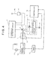
- FIG. 4 is a block diagram of a pump control system according to a second embodiment of the present invention.
- FIG. 5 is a block diagram of a pump control system according to a third embodiment of the present invention.
- FIGS. 1 to 5 Each pump control system embodying the present invention will be described hereinunder with reference to FIGS. 1 to 5 . It is to be understood that the invention is not limited thereto.
- the numeral 1 denotes an engine and numeral 2 denotes a variable displacement type hydraulic pump which is driven by the engine 1 .
- a hydraulic actuator circuit 3 provided with a hydraulic actuator (not shown) such as a hydraulic cylinder or a hydraulic motor is driven with hydraulic oil discharged from the pump 2 .
- the hydraulic actuator circuit 3 there are provided a travel motor circuit for driving a lower travel body, a rotating motor circuit for rotating an upper rotating body, and each cylinder circuit for actuating boom, arm, and bucket, respectively, as excavating attachments.
- Numeral 4 denotes an operating means for operating the hydraulic actuator circuit 3 .
- the operating means 4 is operated with a lever 4 a .
- a pilot pressure proportional to operated amount of the lever 4 a is applied to a hydraulic pilot type control valve (not shown) provided in the hydraulic actuator circuit 3 to actuate the control valve, whereby supply or discharge of oil from the pump 2 is controlled.
- the operating means 4 is provided in a plural number correspondingly to plural actuator operations although only one operating means is illustrated for the simplification of illustration.
- Numeral 5 denotes a pump regulator which is provided with an electromagnetic proportional valve 6 and a tilt driving unit 7 .
- the proportional valve 6 operates in accordance with a command signal provided from a controller 12 .
- the tilt driving unit 7 operates to control the tilting of the pump, whereby the pump discharge rate hereinafter referred to as pump flow rate is controlled.
- Numeral 9 denotes a hydraulic oil source for the pump regulator 5 and the reference mark T denotes a tank.
- ESS control when the pump load (pump pressure) increases and the engine speed decreases, a command signal for decreasing the pump flow rate is provided from the controller 12 to the pump regulator 5 in accordance with a signal provided from an engine speed sensor 10 as detector adapted to detect the number of revolutions of the engine. With this command signal, a control is made so that an absorption torque (horsepower) of the pump 2 is small at a high load and is large at a low load. Consequently, the absorption torque and the engine horsepower are well-balanced and the occurrence of engine stall is prevented.
- Numeral 11 denotes a temperature sensor adapted to detect the temperature of hydraulic oil discharged from the pump 2 .
- a signal of the temperature of the hydraulic oil detected by the sensor 11 is provided to the controller 12 .
- the controller 12 makes the following control.
- the controller 12 controls the pump flow rate through the pump regulator 5 by ESS control so as to afford such a pump horsepower characteristic at room temperature as indicated with a solid line in FIG. 2.
- This ESS control at room temperature will hereinafter be referred to as “room temperature horsepower control.”
- the controller 12 makes the following control.
- the controller 12 controls the pump flow rate by a horsepower decreasing control (low-temperature horsepower control) so as to afford a horsepower characteristic such that absorption horsepower of the pump 2 becomes smaller by a certain value AT than in the room temperature horsepower control relative to the engine speed, as indicated with a broken line in FIG. 2.
- the amount of horsepower decreased, ⁇ T is set so as to become smaller as the detected temperature rises and approaches a preset temperature A, as shown in FIG. 3.
- ⁇ T The amount of horsepower decreased
- this control makes the degree of decrease in the pump flow rate smaller with a rise of the hydraulic oil temperature.
- the degree of decrease in the flow rate becomes smaller and approaches that in the room temperature horsepower control as the hydraulic oil temperature rises, so that there is no fear of a sudden increase of the flow rate to induce a shock at the switching point of control.
- the numeral 13 denotes a starting switch adapted to start the engine 1 .
- the engine 1 Upon turning ON of the starting switch 13 , the engine 1 starts operating in accordance with a signal provided from an engine controller 14 .
- an elapsed time after turning ON of the switch 13 is measured with a timer 15 .
- an unexpiration signal is fed from the timer 15 to a controller 16 .
- the unexpiration signal indicates that the elapsed time does not reach the preset time yet.
- the elapsed time after start-up of the engine is set as the time elapsed until the hydraulic oil temperature reaches the preset temperature, which time can be determined easily by an operation test or the like although it varies depending on the outside air temperature).
- the controller 16 Upon receipt of the unexpiration signal, the controller 16 performs the low temperature horsepower control.
- an after-engine-start timer (a first timer) adapted to measure an elapsed time after start-up of the engine to detect the temperature of the hydraulic oil indirectly.
- a third embodiment of the present invention shows another example of detecting the temperature of the hydraulic oil indirectly.
- a pilot pressure developed upon operation of the operating means 4 is detected by a pressure sensor 17 and the number of the detections, i.e., the number of the operations, is counted by a counter (operation counter) 18 .
- the count value thus obtained is inputted to a controller 19 .
- This third embodiment is constructed in such a manner that when the number of operations performed until the hydraulic oil temperature rises to the preset temperature reaches a preset number of operations, the control made by the controller 19 switches from the low temperature horsepower control to the room temperature horsepower control.
- a first operation counter as a temperature sensor adapted to count the number of operations of a hydraulic actuator to detect the hydraulic oil temperature indirectly.
- an integrated value of pilot pressure is determined by a pilot pressure integrator (operation counting means) 20 and is inputted to the controller 19 .
- a construction may be made such that when this integrated value, i.e., a total operation time, has reached a preset time, a switching is made from the low temperature horsepower control to the room temperature horsepower control.
- the switching to the room temperature horsepower control may be made when it is detected by either some of such indirect detectors as temperature detectors or a combination of an indirect detector and the direct sensor used in the first embodiment that the hydraulic oil temperature has reached the preset temperature.
- a construction may be made such that a greatly load varying operation (e.g., arm pushing operation) which is apt to cause overtorque of the engine 1 or hunting is selected as an actuator operation of the operating means 4 associated with the detection and the low temperature horsepower control is performed only when the actuator operation is conducted at a low temperature.
- a greatly load varying operation e.g., arm pushing operation
- Such a pump control limited to the specific actuator operation is applicable not only to the construction of the third embodiment but also to the constructions of the first and second embodiments, provided means for detecting the specific actuator operation is added.
- the temperature detector there may be used a second operation counter adapted to measure the operation time of a hydraulic actuator to detect the temperature of the hydraulic oil indirectly.
- detectors which detect the hydraulic oil temperature indirectly there are a detector adapted to detect the hydraulic oil temperature indirectly on the basis of an elapsed time after start-up of the engine, a detector adapted to count the number of operations of a hydraulic actuator, and a detector adapted to detect an operated time of a hydraulic actuator. With these detectors, it is not necessary to use a temperature sensor adapted to detect the hydraulic oil temperature directly and the hydraulic oil temperature can be detected by a signal processing performed by a timer or an operation counter.
- both indirect detector and direct sensor may be combined, or plural indirect detectors may be combined, whereby even in the event of failure of one detector, an accurate pump control is ensured by the other detector or sensor.
- a temperature detector there may be used one provided with an after-engine-stop timer (a second timer) adapted to measure an elapsed time after stop of the engine to detect the hydraulic oil temperature indirectly.
- a second timer adapted to measure an elapsed time after stop of the engine to detect the hydraulic oil temperature indirectly.
- the control means may be constructed such that the low temperature horsepower control is performed only when a preselected actuator operation is conducted out of plural actuator operations.
Landscapes
- Engineering & Computer Science (AREA)
- Computer Hardware Design (AREA)
- Mechanical Engineering (AREA)
- General Engineering & Computer Science (AREA)
- Operation Control Of Excavators (AREA)
- Fluid-Pressure Circuits (AREA)
- Steering Control In Accordance With Driving Conditions (AREA)
- Control Of Temperature (AREA)
- Control Of Vehicle Engines Or Engines For Specific Uses (AREA)
- Control Of Positive-Displacement Pumps (AREA)
Abstract
Description
- 1. Field of the Invention
- The present invention relates to a construction machine having a hydraulic pump control system.
- 2. Description of the Related Art
- Generally, for preventing an engine stall in a construction machine, there is performed an engine speed sensing control (hereinafter referred to as “ESS control”) in which a pump horsepower (pump discharge) is controlled in accordance with number of revolutions of an engine, i.e., engine speed or engine revolutions.
- According to the ESS control, when pump load (pump pressure) increases and the engine speed decreases, pump flow rate is decreased. In this case, a control is made so that the pump horsepower becomes small in reply to a large load and becomes large in reply to a small load, and therefore an engine stall is prevented.
- However, the conventional pump control system involves the following problems.
- When a construction machine is operated at a low temperature, for example in the winter season, the temperature of the hydraulic oil and that of the engine oil are low and highly viscous just after start-up of the engine. Under the resistance of these oils, the engine torque increases.
- If in this state there is performed a work of a large load, for example if there is performed an arm pushing operation for an arm as an excavating attachment in a hydraulic excavator, there is conducted a pump horsepower control based on only engine speed by ESS control as is the case with the control at room temperature despite the engine load being large under the aforesaid oil resistance. As a result, the engine torque becomes overtorque, causing a great damage to the engine.
- If the viscosity of the hydraulic oil is high, the reaction of a pump regulator which is operated with the hydraulic oil becomes dull and the response of the pump to a discharge rate command is delayed. Consequently, in a work under a greatly varying load, hunting is apt to occur in the pump discharge rate command pump discharge rate ESS control system.
- It is an object of the present invention to provide a construction machine having a pump control system which can prevent the occurrence of engine overtorque and hunting at low temperatures.
- The construction machine of the present invention comprises an engine; a hydraulic pump which is actuated by the engine; a hydraulic actuator circuit adapted to use the hydraulic pump as a hydraulic oil source; a pump regulator adapted to control discharge rate of hydraulic oil or working oil discharged from the hydraulic pump; an engine speed detecting means such as an engine speed sensor adapted to detect the number of revolutions of the engine; a temperature detector adapted to detect temperature of the hydraulic oil; and a control means adapted to control the discharge rate of the hydraulic pump through the pump regulator. The control means is constructed so as to perform an engine speed sensing control in which the pump flow rate is controlled in accordance with engine speed or engine revolutions. The control means is further constructed so as to perform a low-temperature horsepower control such that in a temperature region wherein the temperature of the hydraulic oil is lower than a preset temperature the pump flow rate relative to the engine speed is decreased to a lower level than when the temperature of the hydraulic oil is not lower than the preset temperature.
- In this connection, when the temperature of the hydraulic oil does not reach the preset temperature (at a lower temperature than the preset temperature), it is possible to perform a low-temperature horsepower control in which the pump horsepower is set lower than when then the temperature is not lower than the preset temperature (at room temperature). With this control, the engine load is diminished, so that it is possible to prevent overtorque of the engine at a low temperature.
- Moreover, according to the low-temperature horsepower control, the absolute value of the pump flow rate is low and the amount of change in the pump flow rate caused by a load variation becomes small, so that hunting is difficult to occur.
- The temperature of engine oil also contributes to overtorque. However, as the temperature of the hydraulic oil rises, the temperature of the engine oil also rises, so that temperature of the engine oil can be detected indirectly by detecting the temperature of the hydraulic oil. Therefore, even without separately detecting the temperature of the engine oil, the desired object can be achieved by detecting the temperature of hydraulic oil and controlling the horsepower in the manner mentioned above.
- Alternatively, the temperature of the hydraulic oil may be detected indirectly by detecting the temperature of the engine oil. Further, since the temperature of engine cooling water is correlated with the temperature of the hydraulic oil, the temperature of the hydraulic oil may be detected indirectly by detecting the temperature of the engine cooling water.
- FIG. 1 is a block diagram of a pump control system according to a first embodiment of the present invention;
- FIG. 2 is a horsepower characteristic diagram showing the results of control made by the control system;
- FIG. 3 is a diagram showing a relation between a horsepower decreasing control made by the control system and detected temperatures;
- FIG. 4 is a block diagram of a pump control system according to a second embodiment of the present invention; and
- FIG. 5 is a block diagram of a pump control system according to a third embodiment of the present invention.
- Each pump control system embodying the present invention will be described hereinunder with reference to FIGS. 1 to 5. It is to be understood that the invention is not limited thereto.
- In the following embodiments the same portions will be identified by the same reference numerals and overlapped explanations thereof will be omitted; only different points will be described.
- First Embodiment (FIGS. 1 to 3)
- In FIG. 1, the
numeral 1 denotes an engine andnumeral 2 denotes a variable displacement type hydraulic pump which is driven by theengine 1. Ahydraulic actuator circuit 3 provided with a hydraulic actuator (not shown) such as a hydraulic cylinder or a hydraulic motor is driven with hydraulic oil discharged from thepump 2. - For example in the case of a hydraulic excavator, as the
hydraulic actuator circuit 3 there are provided a travel motor circuit for driving a lower travel body, a rotating motor circuit for rotating an upper rotating body, and each cylinder circuit for actuating boom, arm, and bucket, respectively, as excavating attachments. - Numeral 4 denotes an operating means for operating the
hydraulic actuator circuit 3. The operating means 4 is operated with alever 4 a. A pilot pressure proportional to operated amount of thelever 4 a is applied to a hydraulic pilot type control valve (not shown) provided in thehydraulic actuator circuit 3 to actuate the control valve, whereby supply or discharge of oil from thepump 2 is controlled. - The operating means 4 is provided in a plural number correspondingly to plural actuator operations although only one operating means is illustrated for the simplification of illustration.
- Numeral 5 denotes a pump regulator which is provided with an electromagnetic
proportional valve 6 and atilt driving unit 7. Theproportional valve 6 operates in accordance with a command signal provided from acontroller 12. With a secondary pressure of theproportional valve 6, thetilt driving unit 7 operates to control the tilting of the pump, whereby the pump discharge rate hereinafter referred to as pump flow rate is controlled. Numeral 9 denotes a hydraulic oil source for thepump regulator 5 and the reference mark T denotes a tank. - According to an ESS control, when the pump load (pump pressure) increases and the engine speed decreases, a command signal for decreasing the pump flow rate is provided from the
controller 12 to thepump regulator 5 in accordance with a signal provided from anengine speed sensor 10 as detector adapted to detect the number of revolutions of the engine. With this command signal, a control is made so that an absorption torque (horsepower) of thepump 2 is small at a high load and is large at a low load. Consequently, the absorption torque and the engine horsepower are well-balanced and the occurrence of engine stall is prevented. - Numeral 11 denotes a temperature sensor adapted to detect the temperature of hydraulic oil discharged from the
pump 2. A signal of the temperature of the hydraulic oil detected by thesensor 11 is provided to thecontroller 12. - In this case, since the temperature of the hydraulic oil is detected directly, accurate detection can be done without being affected by a change in outside air temperature, as compared with an indirect detection. Therefore, a more accurate pump control can be effected while keeping a switching temperature of the control constant.
- Although in FIG. 1 the hydraulic oil temperature in a pump discharge line is detected by the
sensor 11, there may be detected a hydraulic oil temperature in thecircuit 3 or in the tank T. - When the detected hydraulic oil temperature is not lower than a preset temperature (a temperature at which there is no fear of engine overtorque or hunting), the
controller 12 makes the following control. Thecontroller 12 controls the pump flow rate through thepump regulator 5 by ESS control so as to afford such a pump horsepower characteristic at room temperature as indicated with a solid line in FIG. 2. This ESS control at room temperature will hereinafter be referred to as “room temperature horsepower control.” - On the other hand, when the hydraulic oil temperature does not reach the preset temperature(or being lower than the preset temperature), the
controller 12 makes the following control. Thecontroller 12 controls the pump flow rate by a horsepower decreasing control (low-temperature horsepower control) so as to afford a horsepower characteristic such that absorption horsepower of thepump 2 becomes smaller by a certain value AT than in the room temperature horsepower control relative to the engine speed, as indicated with a broken line in FIG. 2. - According to such pump controls, at a low temperature at which the hydraulic oil temperature is low and a rotational resistance of the
engine 1 is high, the burden on theengine 1 can be decreased than at room temperature. Consequently, it is possible to prevent overtorque of theengine 1. - In the low-temperature horsepower control, moreover, hunting is difficult to occur because the absolute value of the pump flow rate is low and the amount of a change in the flow rate is small.
- The amount of horsepower decreased, ΔT, is set so as to become smaller as the detected temperature rises and approaches a preset temperature A, as shown in FIG. 3. When the detected temperature reaches the preset temperature A, a switching is made to the room temperature horsepower control.
- Thus, since the amount of horsepower decreased, ΔT, decreases gradually in accordance with a rise of the hydraulic oil temperature and a switching is made naturally to the room temperature horsepower control, there is no fear of a sudden increase of the flow rate at the switching point of control and hence a shock is not likely to occur at all.
- In short, this control makes the degree of decrease in the pump flow rate smaller with a rise of the hydraulic oil temperature. In this case, the degree of decrease in the flow rate becomes smaller and approaches that in the room temperature horsepower control as the hydraulic oil temperature rises, so that there is no fear of a sudden increase of the flow rate to induce a shock at the switching point of control.
- Second Embodiment (see FIG. 4)
- In FIG. 4, the numeral 13 denotes a starting switch adapted to start the
engine 1. Upon turning ON of the startingswitch 13, theengine 1 starts operating in accordance with a signal provided from anengine controller 14. - In this embodiment, an elapsed time after turning ON of the switch 13 (an elapsed time after start-up of the engine 1) is measured with a
timer 15. Until the elapsed time reaches a preset time, an unexpiration signal is fed from thetimer 15 to acontroller 16. The unexpiration signal indicates that the elapsed time does not reach the preset time yet. - The elapsed time after start-up of the engine is set as the time elapsed until the hydraulic oil temperature reaches the preset temperature, which time can be determined easily by an operation test or the like although it varies depending on the outside air temperature). Upon receipt of the unexpiration signal, the
controller 16 performs the low temperature horsepower control. - When the elapsed time reaches the preset time, an expiration signal is fed from the
timer 15 to thecontroller 16 and a switching is made to the room temperature horsepower control. - Just after stop of the
engine 1, the hydraulic oil temperature is high. Therefore, it is desirable to construct the control system so that the room temperature horsepower control continues if the engine is re-started within a certain time after turning OFF of the engine. By so doing, there is no fear of the working efficiency being deteriorated by a wasteful horsepower decreasing control. - In this embodiment, as a temperature sensor there is used an after-engine-start timer (a first timer) adapted to measure an elapsed time after start-up of the engine to detect the temperature of the hydraulic oil indirectly.
- Third Embodiment (see FIG. 5)
- A third embodiment of the present invention shows another example of detecting the temperature of the hydraulic oil indirectly. A pilot pressure developed upon operation of the operating means 4 is detected by a
pressure sensor 17 and the number of the detections, i.e., the number of the operations, is counted by a counter (operation counter) 18. The count value thus obtained is inputted to acontroller 19. This third embodiment is constructed in such a manner that when the number of operations performed until the hydraulic oil temperature rises to the preset temperature reaches a preset number of operations, the control made by thecontroller 19 switches from the low temperature horsepower control to the room temperature horsepower control. - In this embodiment there is provided a first operation counter as a temperature sensor adapted to count the number of operations of a hydraulic actuator to detect the hydraulic oil temperature indirectly.
- According to the constructions of the second and third embodiments, it is not necessary to use a temperature sensor and the temperature can be detected through signal processings performed in the
timer 15 and thecounter 18. Consequently, it is possible to reduce the equipment cost. - As indicated with a dash-double dot line in FIG. 5, an integrated value of pilot pressure is determined by a pilot pressure integrator (operation counting means) 20 and is inputted to the
controller 19. A construction may be made such that when this integrated value, i.e., a total operation time, has reached a preset time, a switching is made from the low temperature horsepower control to the room temperature horsepower control. - Alternatively, the switching to the room temperature horsepower control may be made when it is detected by either some of such indirect detectors as temperature detectors or a combination of an indirect detector and the direct sensor used in the first embodiment that the hydraulic oil temperature has reached the preset temperature.
- By so doing, even in the event one detector should be at fault, an accurate pump control is ensured by the other detector or sensor.
- On the other hand, in the third embodiment shown in FIG. 5, a construction may be made such that a greatly load varying operation (e.g., arm pushing operation) which is apt to cause overtorque of the
engine 1 or hunting is selected as an actuator operation of the operating means 4 associated with the detection and the low temperature horsepower control is performed only when the actuator operation is conducted at a low temperature. - By so doing, there is no fear that the low temperature horsepower control may be conducted wastefully in a such a light work as is not likely to cause overtorque or hunting, which wasteful control would cause a lowering of the working efficiency.
- Such a pump control limited to the specific actuator operation is applicable not only to the construction of the third embodiment but also to the constructions of the first and second embodiments, provided means for detecting the specific actuator operation is added.
- As the temperature detector there may be used a second operation counter adapted to measure the operation time of a hydraulic actuator to detect the temperature of the hydraulic oil indirectly.
- As detectors which detect the hydraulic oil temperature indirectly there are a detector adapted to detect the hydraulic oil temperature indirectly on the basis of an elapsed time after start-up of the engine, a detector adapted to count the number of operations of a hydraulic actuator, and a detector adapted to detect an operated time of a hydraulic actuator. With these detectors, it is not necessary to use a temperature sensor adapted to detect the hydraulic oil temperature directly and the hydraulic oil temperature can be detected by a signal processing performed by a timer or an operation counter.
- Of course, both indirect detector and direct sensor may be combined, or plural indirect detectors may be combined, whereby even in the event of failure of one detector, an accurate pump control is ensured by the other detector or sensor.
- As a temperature detector there may be used one provided with an after-engine-stop timer (a second timer) adapted to measure an elapsed time after stop of the engine to detect the hydraulic oil temperature indirectly.
- In this case, even after turning OFF of the engine, the hydraulic oil temperature is high just after the engine stop and the room temperature horsepower control is performed. Thus, there is no fear that the working efficiency may be deteriorated by a wasteful horsepower decreasing control.
- The control means may be constructed such that the low temperature horsepower control is performed only when a preselected actuator operation is conducted out of plural actuator operations.
- In this case, since the low temperature horsepower control is made only when the preselected actuator operation is performed, if there is selected as an actuator operation a greatly load varying operation (e.g., arm pushing operation) which is apt to cause engine overtoque or hunting, there no fear of occurrence of such an inconvenience as a wasteful low temperature horsepower control to lower the working efficiency.
- Although an embodiment of the present invention has been described above, the scope of protection of the present invention is not limited thereto.
Claims (8)
Applications Claiming Priority (2)
| Application Number | Priority Date | Filing Date | Title |
|---|---|---|---|
| JP2001-175241 | 2001-06-11 | ||
| JP2001175241A JP3775245B2 (en) | 2001-06-11 | 2001-06-11 | Pump controller for construction machinery |
Publications (2)
| Publication Number | Publication Date |
|---|---|
| US20020184881A1 true US20020184881A1 (en) | 2002-12-12 |
| US6655135B2 US6655135B2 (en) | 2003-12-02 |
Family
ID=19016415
Family Applications (1)
| Application Number | Title | Priority Date | Filing Date |
|---|---|---|---|
| US10/150,934 Expired - Lifetime US6655135B2 (en) | 2001-06-11 | 2002-05-21 | Construction machine |
Country Status (5)
| Country | Link |
|---|---|
| US (1) | US6655135B2 (en) |
| EP (1) | EP1267075B1 (en) |
| JP (1) | JP3775245B2 (en) |
| AT (1) | ATE445781T1 (en) |
| DE (1) | DE60233996D1 (en) |
Cited By (8)
| Publication number | Priority date | Publication date | Assignee | Title |
|---|---|---|---|---|
| US7001100B1 (en) * | 2004-11-01 | 2006-02-21 | Attar Adil H | Monolithically formed one-piece reflective pavement marker |
| US7111458B2 (en) | 2003-07-11 | 2006-09-26 | Sauer-Danfoss Inc. | Electrical loop flushing system |
| US20100154403A1 (en) * | 2008-12-18 | 2010-06-24 | Caterpillar Inc. | System and method for operating a variable displacement hydraulic pump |
| US20130248306A1 (en) * | 2011-05-30 | 2013-09-26 | Kayaba Industry Co., Ltd. | Vibration control device for railroad vehicle |
| CN104819183A (en) * | 2015-03-25 | 2015-08-05 | 西安建筑科技大学 | Variable-rotating-speed hydraulic power source flow control system and method |
| CN104981615A (en) * | 2013-02-19 | 2015-10-14 | 沃尔沃建造设备有限公司 | Hydraulic system for construction machine, provided with protection device |
| US9233695B2 (en) | 2011-06-20 | 2016-01-12 | Kayaba Industry Co., Ltd. | Railcar damping device |
| US9358990B2 (en) | 2011-06-20 | 2016-06-07 | Kyb Corporation | Railcar damping device |
Families Citing this family (18)
| Publication number | Priority date | Publication date | Assignee | Title |
|---|---|---|---|---|
| JP4551291B2 (en) * | 2005-08-02 | 2010-09-22 | 株式会社ジェイテクト | Driving force distribution device |
| JP4542964B2 (en) * | 2005-08-02 | 2010-09-15 | 株式会社ジェイテクト | Driving force distribution device |
| JP4353190B2 (en) * | 2006-02-27 | 2009-10-28 | コベルコ建機株式会社 | Hydraulic circuit for construction machinery |
| JP5084295B2 (en) * | 2007-02-09 | 2012-11-28 | 日立建機株式会社 | Pump torque control device for hydraulic construction machinery |
| US8234860B2 (en) * | 2008-08-29 | 2012-08-07 | Caterpillar Inc. | Machine control system having hydraulic warmup procedure |
| US8096781B2 (en) * | 2008-09-24 | 2012-01-17 | Caterpillar Inc. | Hydraulic pump system with reduced cold start parasitic loss |
| DE102008054880A1 (en) * | 2008-12-18 | 2010-07-01 | Deere & Company, Moline | hydraulic system |
| JP2011032942A (en) * | 2009-08-03 | 2011-02-17 | Caterpillar Sarl | Pump control system in motor-driven hydraulic working machine |
| US8429908B2 (en) * | 2009-12-17 | 2013-04-30 | Deere & Company | Hydraulic system |
| JP5688991B2 (en) * | 2011-02-09 | 2015-03-25 | 株式会社タダノ | Work machine |
| US9416720B2 (en) | 2011-12-01 | 2016-08-16 | Paccar Inc | Systems and methods for controlling a variable speed water pump |
| EP2889433B1 (en) | 2013-12-20 | 2019-05-01 | Doosan Infracore Co., Ltd. | System and method of controlling vehicle of construction equipment |
| KR102181125B1 (en) * | 2013-12-20 | 2020-11-20 | 두산인프라코어 주식회사 | Apparatus and method for controlling vehicle of construction equipment |
| JP6252770B2 (en) | 2014-03-26 | 2017-12-27 | 株式会社豊田自動織機 | Vehicle with hydraulic actuator |
| JP6814440B2 (en) * | 2017-06-21 | 2021-01-20 | コベルコ建機株式会社 | Work machine |
| JP7450451B2 (en) | 2020-04-30 | 2024-03-15 | 日立建機株式会社 | working machine |
| JP2023183040A (en) | 2022-06-15 | 2023-12-27 | キャタピラー エス エー アール エル | Construction machinery hydraulic circuit |
| CN119038466A (en) * | 2024-09-10 | 2024-11-29 | 湖南星邦智能装备股份有限公司 | Power control method and control system for aerial working platform |
Citations (3)
| Publication number | Priority date | Publication date | Assignee | Title |
|---|---|---|---|---|
| US5176504A (en) * | 1989-07-27 | 1993-01-05 | Kabushiki Kaisha Komatsu Seisakusho | Apparatus for controlling hydraulic pumps for construction machine |
| US5410878A (en) * | 1993-06-30 | 1995-05-02 | Samsung Heavy Industry Co., Ltd. | Automatic warming-up apparatus and method thereof in hydraulic system |
| US5758499A (en) * | 1995-03-03 | 1998-06-02 | Hitachi Construction Machinery Co., Ltd. | Hydraulic control system |
Family Cites Families (3)
| Publication number | Priority date | Publication date | Assignee | Title |
|---|---|---|---|---|
| KR950007624B1 (en) * | 1990-09-28 | 1995-07-13 | 히다찌 겐끼 가부시기가이샤 | Control device of hydraulic pump |
| US5564274A (en) * | 1995-12-13 | 1996-10-15 | Caterpillar Inc. | Cold oil protection circuit for a hydraulic system |
| JP2001041204A (en) * | 1999-07-27 | 2001-02-13 | Sumitomo Constr Mach Co Ltd | Hydraulic circuit |
-
2001
- 2001-06-11 JP JP2001175241A patent/JP3775245B2/en not_active Expired - Fee Related
-
2002
- 2002-05-21 US US10/150,934 patent/US6655135B2/en not_active Expired - Lifetime
- 2002-06-04 AT AT02012266T patent/ATE445781T1/en not_active IP Right Cessation
- 2002-06-04 EP EP02012266A patent/EP1267075B1/en not_active Expired - Lifetime
- 2002-06-04 DE DE60233996T patent/DE60233996D1/en not_active Expired - Lifetime
Patent Citations (3)
| Publication number | Priority date | Publication date | Assignee | Title |
|---|---|---|---|---|
| US5176504A (en) * | 1989-07-27 | 1993-01-05 | Kabushiki Kaisha Komatsu Seisakusho | Apparatus for controlling hydraulic pumps for construction machine |
| US5410878A (en) * | 1993-06-30 | 1995-05-02 | Samsung Heavy Industry Co., Ltd. | Automatic warming-up apparatus and method thereof in hydraulic system |
| US5758499A (en) * | 1995-03-03 | 1998-06-02 | Hitachi Construction Machinery Co., Ltd. | Hydraulic control system |
Cited By (12)
| Publication number | Priority date | Publication date | Assignee | Title |
|---|---|---|---|---|
| US7111458B2 (en) | 2003-07-11 | 2006-09-26 | Sauer-Danfoss Inc. | Electrical loop flushing system |
| US7001100B1 (en) * | 2004-11-01 | 2006-02-21 | Attar Adil H | Monolithically formed one-piece reflective pavement marker |
| US20100154403A1 (en) * | 2008-12-18 | 2010-06-24 | Caterpillar Inc. | System and method for operating a variable displacement hydraulic pump |
| US8393150B2 (en) | 2008-12-18 | 2013-03-12 | Caterpillar Inc. | System and method for operating a variable displacement hydraulic pump |
| US20130248306A1 (en) * | 2011-05-30 | 2013-09-26 | Kayaba Industry Co., Ltd. | Vibration control device for railroad vehicle |
| US8997950B2 (en) * | 2011-05-30 | 2015-04-07 | Kayaba Industry Co., Ltd. | Vibration control device for railroad vehicle |
| US9233695B2 (en) | 2011-06-20 | 2016-01-12 | Kayaba Industry Co., Ltd. | Railcar damping device |
| US9358990B2 (en) | 2011-06-20 | 2016-06-07 | Kyb Corporation | Railcar damping device |
| CN104981615A (en) * | 2013-02-19 | 2015-10-14 | 沃尔沃建造设备有限公司 | Hydraulic system for construction machine, provided with protection device |
| US20160003265A1 (en) * | 2013-02-19 | 2016-01-07 | Hea-Gyoon Joung | Hydraulic system for construction machine, provided with protection device |
| US9790965B2 (en) * | 2013-02-19 | 2017-10-17 | Volvo Construction Equipment Ab | Hydraulic system for construction machine, provided with protection device |
| CN104819183A (en) * | 2015-03-25 | 2015-08-05 | 西安建筑科技大学 | Variable-rotating-speed hydraulic power source flow control system and method |
Also Published As
| Publication number | Publication date |
|---|---|
| JP3775245B2 (en) | 2006-05-17 |
| EP1267075A3 (en) | 2004-07-28 |
| EP1267075A2 (en) | 2002-12-18 |
| DE60233996D1 (en) | 2009-11-26 |
| EP1267075B1 (en) | 2009-10-14 |
| JP2002364603A (en) | 2002-12-18 |
| US6655135B2 (en) | 2003-12-02 |
| ATE445781T1 (en) | 2009-10-15 |
Similar Documents
| Publication | Publication Date | Title |
|---|---|---|
| US6655135B2 (en) | Construction machine | |
| EP2518220B1 (en) | Apparatus and method for controlling a hydraulic pump of a construction machine | |
| JP3098859B2 (en) | Variable displacement hydraulic pump and control method of hydraulic pump driven engine | |
| US8056331B2 (en) | Pump torque controller of hydraulic working machine | |
| KR100693676B1 (en) | Fan speed control method | |
| KR101778225B1 (en) | A method for controlling hydraulic pump in construction machine | |
| US6314727B1 (en) | Method and apparatus for controlling an electro-hydraulic fluid system | |
| US6202411B1 (en) | Flow rate control device in a hydraulic excavator | |
| EP0277253A1 (en) | Hydraulic pump control unit | |
| US6195989B1 (en) | Power control system for a machine | |
| EP1574627A1 (en) | Emergency control method for a work device of a construction equipment | |
| JP2000205141A (en) | Method and device for diagnosing failure of pump | |
| JP3088565B2 (en) | Hydraulic pump control device for hydraulic drive machine and control method therefor | |
| JP2896366B2 (en) | Method and apparatus for controlling hydraulic pump of hydraulic drive machine | |
| JP3580941B2 (en) | Engine speed control device for hydraulic construction machinery | |
| US20240416992A1 (en) | Hydraulic pump assembly | |
| JPH11182443A (en) | Control unit of variable displacement hydraulic pump | |
| JPH04143428A (en) | Controller for construction machinery | |
| KR100499286B1 (en) | Engine operating mode change device | |
| JPH06248666A (en) | Hydraulic control equipment for hydraulic construction machinery | |
| GB2578554A (en) | Hydraulic system | |
| US20170350096A1 (en) | Hydraulic pump control apparatus for construction equipment and control method thereof | |
| JP3137299B2 (en) | Hydraulic control device for construction machinery | |
| JPH11270514A (en) | Hydraulic control device | |
| KR950029598A (en) | Pump control device of hydraulic construction machine |
Legal Events
| Date | Code | Title | Description |
|---|---|---|---|
| AS | Assignment |
Owner name: KOBELCO CONSTRUCTION MACHINERY CO., LTD., JAPAN Free format text: ASSIGNMENT OF ASSIGNORS INTEREST;ASSIGNOR:OKA, HIDEKAZU;REEL/FRAME:013693/0366 Effective date: 20020509 |
|
| STCF | Information on status: patent grant |
Free format text: PATENTED CASE |
|
| FEPP | Fee payment procedure |
Free format text: PAYOR NUMBER ASSIGNED (ORIGINAL EVENT CODE: ASPN); ENTITY STATUS OF PATENT OWNER: LARGE ENTITY Free format text: PAYER NUMBER DE-ASSIGNED (ORIGINAL EVENT CODE: RMPN); ENTITY STATUS OF PATENT OWNER: LARGE ENTITY |
|
| FPAY | Fee payment |
Year of fee payment: 4 |
|
| FPAY | Fee payment |
Year of fee payment: 8 |
|
| FPAY | Fee payment |
Year of fee payment: 12 |