US20020184841A1 - Structures, window protection systems and methods for protecting glass panes during storms - Google Patents
Structures, window protection systems and methods for protecting glass panes during storms Download PDFInfo
- Publication number
- US20020184841A1 US20020184841A1 US09/878,214 US87821401A US2002184841A1 US 20020184841 A1 US20020184841 A1 US 20020184841A1 US 87821401 A US87821401 A US 87821401A US 2002184841 A1 US2002184841 A1 US 2002184841A1
- Authority
- US
- United States
- Prior art keywords
- compressible
- recited
- glass pane
- compressible material
- window
- Prior art date
- Legal status (The legal status is an assumption and is not a legal conclusion. Google has not performed a legal analysis and makes no representation as to the accuracy of the status listed.)
- Granted
Links
- 239000011521 glass Substances 0.000 title claims abstract description 175
- 238000000034 method Methods 0.000 title claims description 12
- 239000000463 material Substances 0.000 claims abstract description 182
- 238000007493 shaping process Methods 0.000 claims abstract description 122
- 239000006261 foam material Substances 0.000 claims abstract description 6
- 239000006260 foam Substances 0.000 claims description 33
- 230000001070 adhesive effect Effects 0.000 claims description 21
- 239000000853 adhesive Substances 0.000 claims description 20
- 239000002245 particle Substances 0.000 claims description 4
- 238000004891 communication Methods 0.000 claims description 2
- 239000012530 fluid Substances 0.000 claims 6
- 230000000149 penetrating effect Effects 0.000 claims 2
- 239000010410 layer Substances 0.000 description 49
- 239000012790 adhesive layer Substances 0.000 description 23
- -1 polyethylene Polymers 0.000 description 10
- 229920002635 polyurethane Polymers 0.000 description 10
- 239000004814 polyurethane Substances 0.000 description 10
- 230000000694 effects Effects 0.000 description 9
- 239000004698 Polyethylene Substances 0.000 description 7
- 229920000573 polyethylene Polymers 0.000 description 7
- 229910052770 Uranium Inorganic materials 0.000 description 6
- 230000006835 compression Effects 0.000 description 6
- 238000007906 compression Methods 0.000 description 6
- 239000011120 plywood Substances 0.000 description 5
- 239000004820 Pressure-sensitive adhesive Substances 0.000 description 4
- 239000011148 porous material Substances 0.000 description 4
- 230000001681 protective effect Effects 0.000 description 4
- ZWEHNKRNPOVVGH-UHFFFAOYSA-N 2-Butanone Chemical compound CCC(C)=O ZWEHNKRNPOVVGH-UHFFFAOYSA-N 0.000 description 3
- 238000010521 absorption reaction Methods 0.000 description 3
- 239000003054 catalyst Substances 0.000 description 3
- 239000011248 coating agent Substances 0.000 description 3
- 238000000576 coating method Methods 0.000 description 3
- 229920001971 elastomer Polymers 0.000 description 3
- 238000011065 in-situ storage Methods 0.000 description 3
- 238000003475 lamination Methods 0.000 description 3
- 229910052751 metal Inorganic materials 0.000 description 3
- 239000005060 rubber Substances 0.000 description 3
- 238000003860 storage Methods 0.000 description 3
- 239000002023 wood Substances 0.000 description 3
- XMGQYMWWDOXHJM-JTQLQIEISA-N (+)-α-limonene Chemical compound CC(=C)[C@@H]1CCC(C)=CC1 XMGQYMWWDOXHJM-JTQLQIEISA-N 0.000 description 2
- NIXOWILDQLNWCW-UHFFFAOYSA-M Acrylate Chemical compound [O-]C(=O)C=C NIXOWILDQLNWCW-UHFFFAOYSA-M 0.000 description 2
- 229920002943 EPDM rubber Polymers 0.000 description 2
- 229920005830 Polyurethane Foam Polymers 0.000 description 2
- PPBRXRYQALVLMV-UHFFFAOYSA-N Styrene Chemical compound C=CC1=CC=CC=C1 PPBRXRYQALVLMV-UHFFFAOYSA-N 0.000 description 2
- 239000003795 chemical substances by application Substances 0.000 description 2
- 239000002131 composite material Substances 0.000 description 2
- 238000010276 construction Methods 0.000 description 2
- 239000004620 low density foam Substances 0.000 description 2
- 239000007769 metal material Substances 0.000 description 2
- 239000000203 mixture Substances 0.000 description 2
- 239000000123 paper Substances 0.000 description 2
- 230000035515 penetration Effects 0.000 description 2
- 230000002093 peripheral effect Effects 0.000 description 2
- 229920000728 polyester Polymers 0.000 description 2
- 229920000642 polymer Polymers 0.000 description 2
- 229920005862 polyol Polymers 0.000 description 2
- 150000003077 polyols Chemical class 0.000 description 2
- 239000011496 polyurethane foam Substances 0.000 description 2
- 239000002904 solvent Substances 0.000 description 2
- 239000002993 sponge (artificial) Substances 0.000 description 2
- 229920003048 styrene butadiene rubber Polymers 0.000 description 2
- 239000004215 Carbon black (E152) Substances 0.000 description 1
- 229920001651 Cyanoacrylate Polymers 0.000 description 1
- 239000004593 Epoxy Substances 0.000 description 1
- JOYRKODLDBILNP-UHFFFAOYSA-N Ethyl urethane Chemical compound CCOC(N)=O JOYRKODLDBILNP-UHFFFAOYSA-N 0.000 description 1
- MWCLLHOVUTZFKS-UHFFFAOYSA-N Methyl cyanoacrylate Chemical compound COC(=O)C(=C)C#N MWCLLHOVUTZFKS-UHFFFAOYSA-N 0.000 description 1
- 229920001730 Moisture cure polyurethane Polymers 0.000 description 1
- CTQNGGLPUBDAKN-UHFFFAOYSA-N O-Xylene Chemical compound CC1=CC=CC=C1C CTQNGGLPUBDAKN-UHFFFAOYSA-N 0.000 description 1
- 239000004952 Polyamide Substances 0.000 description 1
- 239000005062 Polybutadiene Substances 0.000 description 1
- 239000004721 Polyphenylene oxide Substances 0.000 description 1
- 239000004743 Polypropylene Substances 0.000 description 1
- 239000004793 Polystyrene Substances 0.000 description 1
- 229920002323 Silicone foam Polymers 0.000 description 1
- 239000002174 Styrene-butadiene Substances 0.000 description 1
- HCHKCACWOHOZIP-UHFFFAOYSA-N Zinc Chemical compound [Zn] HCHKCACWOHOZIP-UHFFFAOYSA-N 0.000 description 1
- 230000001464 adherent effect Effects 0.000 description 1
- 150000001298 alcohols Chemical class 0.000 description 1
- 150000001338 aliphatic hydrocarbons Chemical class 0.000 description 1
- 229910052782 aluminium Inorganic materials 0.000 description 1
- XAGFODPZIPBFFR-UHFFFAOYSA-N aluminium Chemical compound [Al] XAGFODPZIPBFFR-UHFFFAOYSA-N 0.000 description 1
- 150000001412 amines Chemical class 0.000 description 1
- 150000004945 aromatic hydrocarbons Chemical class 0.000 description 1
- 150000001558 benzoic acid derivatives Chemical class 0.000 description 1
- 230000015572 biosynthetic process Effects 0.000 description 1
- 229910052797 bismuth Inorganic materials 0.000 description 1
- JCXGWMGPZLAOME-UHFFFAOYSA-N bismuth atom Chemical compound [Bi] JCXGWMGPZLAOME-UHFFFAOYSA-N 0.000 description 1
- 229920001400 block copolymer Polymers 0.000 description 1
- 238000006243 chemical reaction Methods 0.000 description 1
- 229920001577 copolymer Polymers 0.000 description 1
- 229920003020 cross-linked polyethylene Polymers 0.000 description 1
- 239000004703 cross-linked polyethylene Substances 0.000 description 1
- 238000013016 damping Methods 0.000 description 1
- HDERJYVLTPVNRI-UHFFFAOYSA-N ethene;ethenyl acetate Chemical group C=C.CC(=O)OC=C HDERJYVLTPVNRI-UHFFFAOYSA-N 0.000 description 1
- LYCAIKOWRPUZTN-UHFFFAOYSA-N ethylene glycol Natural products OCCO LYCAIKOWRPUZTN-UHFFFAOYSA-N 0.000 description 1
- 239000005038 ethylene vinyl acetate Substances 0.000 description 1
- 239000000835 fiber Substances 0.000 description 1
- 239000011152 fibreglass Substances 0.000 description 1
- 238000005187 foaming Methods 0.000 description 1
- 239000012634 fragment Substances 0.000 description 1
- 239000004619 high density foam Substances 0.000 description 1
- 229920005669 high impact polystyrene Polymers 0.000 description 1
- 239000004797 high-impact polystyrene Substances 0.000 description 1
- 239000012943 hotmelt Substances 0.000 description 1
- 229930195733 hydrocarbon Natural products 0.000 description 1
- 150000002430 hydrocarbons Chemical class 0.000 description 1
- WGCNASOHLSPBMP-UHFFFAOYSA-N hydroxyacetaldehyde Natural products OCC=O WGCNASOHLSPBMP-UHFFFAOYSA-N 0.000 description 1
- 238000003780 insertion Methods 0.000 description 1
- 230000037431 insertion Effects 0.000 description 1
- 238000009434 installation Methods 0.000 description 1
- 238000004519 manufacturing process Methods 0.000 description 1
- 238000005259 measurement Methods 0.000 description 1
- 230000007246 mechanism Effects 0.000 description 1
- 239000012528 membrane Substances 0.000 description 1
- 239000002184 metal Substances 0.000 description 1
- 229910001092 metal group alloy Inorganic materials 0.000 description 1
- 238000012986 modification Methods 0.000 description 1
- 230000004048 modification Effects 0.000 description 1
- 125000002524 organometallic group Chemical group 0.000 description 1
- 239000003208 petroleum Substances 0.000 description 1
- XNGIFLGASWRNHJ-UHFFFAOYSA-L phthalate(2-) Chemical compound [O-]C(=O)C1=CC=CC=C1C([O-])=O XNGIFLGASWRNHJ-UHFFFAOYSA-L 0.000 description 1
- 229920003023 plastic Polymers 0.000 description 1
- 239000004033 plastic Substances 0.000 description 1
- 229920001084 poly(chloroprene) Polymers 0.000 description 1
- 229920002647 polyamide Polymers 0.000 description 1
- 229920002857 polybutadiene Polymers 0.000 description 1
- 229920000570 polyether Polymers 0.000 description 1
- 239000002861 polymer material Substances 0.000 description 1
- 229920000098 polyolefin Polymers 0.000 description 1
- 229920001155 polypropylene Polymers 0.000 description 1
- 229920001296 polysiloxane Polymers 0.000 description 1
- 229920002223 polystyrene Polymers 0.000 description 1
- 229920006327 polystyrene foam Polymers 0.000 description 1
- 229920002689 polyvinyl acetate Polymers 0.000 description 1
- 239000011118 polyvinyl acetate Substances 0.000 description 1
- 239000004800 polyvinyl chloride Substances 0.000 description 1
- 239000003380 propellant Substances 0.000 description 1
- 239000011241 protective layer Substances 0.000 description 1
- 230000000717 retained effect Effects 0.000 description 1
- 238000007789 sealing Methods 0.000 description 1
- 230000035939 shock Effects 0.000 description 1
- 239000002356 single layer Substances 0.000 description 1
- 239000007921 spray Substances 0.000 description 1
- 150000003440 styrenes Chemical class 0.000 description 1
- 239000000126 substance Substances 0.000 description 1
- 229920002554 vinyl polymer Polymers 0.000 description 1
- 239000008096 xylene Substances 0.000 description 1
- 229910052725 zinc Inorganic materials 0.000 description 1
- 239000011701 zinc Substances 0.000 description 1
Images


Classifications
-
- E—FIXED CONSTRUCTIONS
- E06—DOORS, WINDOWS, SHUTTERS, OR ROLLER BLINDS IN GENERAL; LADDERS
- E06B—FIXED OR MOVABLE CLOSURES FOR OPENINGS IN BUILDINGS, VEHICLES, FENCES OR LIKE ENCLOSURES IN GENERAL, e.g. DOORS, WINDOWS, BLINDS, GATES
- E06B9/00—Screening or protective devices for wall or similar openings, with or without operating or securing mechanisms; Closures of similar construction
- E06B9/02—Shutters, movable grilles, or other safety closing devices, e.g. against burglary
-
- E—FIXED CONSTRUCTIONS
- E06—DOORS, WINDOWS, SHUTTERS, OR ROLLER BLINDS IN GENERAL; LADDERS
- E06B—FIXED OR MOVABLE CLOSURES FOR OPENINGS IN BUILDINGS, VEHICLES, FENCES OR LIKE ENCLOSURES IN GENERAL, e.g. DOORS, WINDOWS, BLINDS, GATES
- E06B9/00—Screening or protective devices for wall or similar openings, with or without operating or securing mechanisms; Closures of similar construction
- E06B2009/005—Storm panels; hurricane shutters
Definitions
- the present invention relates to protection of glass panes during storm conditions and, more particularly, to structures positioned over glass panes to absorb forces from high winds and wind-borne debris to protect the glass panes from shattering and damage.
- Storm shutters are fabricated to fit the exact measurements of window structures, including glass panes, to be protected and have the disadvantages of being expensive and requiring substantial time for fabrication such that storm shutters are not available unless ordered well in advance of a storm.
- Plywood sheets are generally sold in four-foot by eight-foot sheets with a thickness of 5 ⁇ 8 inch such that the plywood sheets weigh approximately 50 pounds each.
- the plywood sheets must be cut to fit the size of the window structures and are normally drilled and screwed into the building or window frame requiring craftsmanship, labor and hardware and, thus, having the disadvantages of being expensive and requiring substantial time to cover windows when a storm is approaching as well as being extremely heavy.
- Lamination systems such as those supplied by 3M Corporation (e.g.
- Scotchshield have the disadvantages of being films applied to the interior of the glass panes since they are designed to prevent shattered glass from collapsing to thereby prevent rain damage and glass fragments from becoming projectiles.
- the film is not particularly effective in preventing the glass from shattering and does not make the glass more shatter resistant. Since the film is usually on the interior of the glass, it cannot absorb enough energy from the glass fast enough to prevent a failure or fracture of the glass if the glass pane is struck by debris or projectiles. Accordingly, the primary use of lamination systems is to prevent shattered glass from falling apart. Taping of windows results, at best, in the holding of most of a fractured glass pane in place to reduce rain damage and the risk of individuals being cut.
- U.S. Pat. No. 3,830,760 to Benngston and U.S. Pat. No. 4,596,725 to Kluth et al are exemplary of polyurethane foams and discuss one-component and two-component polyurethanes.
- Another object of the present invention is to protect glass panes in buildings from storm damage by temporarily positioning a compressible structure over a glass pane and, after the storm passes, removing the compressible structure.
- a further object of the present invention is to position a shaping member over a glass pane of a window structure in a building, wherein the shaping member is filled, prior to or subsequent to being positioned over the glass pane, with a fluidic compressible material which dries or cures to form a layer of solidified compressible material of sufficient thickness and properties to absorb energy from debris striking the shaping member during a storm.
- Another object of the present invention is to utilize a shaping member to shape a fluidic polymeric foam material applied over a glass pane of a window structure such that the fluidic compressible material hardens to form a layer of solidified compressible material temporarily protecting the glass pane from damage due to storms.
- An additional object of the present invention is to inflate a shaping member to a desired size in response to being filled, partially or entirely, with a fluidic compressible material which solidifies to form a compressible structure to protect a glass pane of a window structure in a building from storm damage.
- the present invention has as a further object to position a plurality of compressible structures over a glass pane of a window structure in a building, with the plurality of compressible structures covering the surface area of the glass pane to protect the glass pane from damage due to storms.
- Yet another object of the present invention is to removably secure one or more pre-fabricated, polymeric foam panels over a glass pane of a window structure in a building to protect the glass pane from damage during storms.
- Still a further object of the present invention is to enhance the effectiveness of a compressible structure positioned over a glass pane of a window structure in a building to protect the glass pane from storm damage by utilizing a combination of solidified compressible materials of different densities in the compressible structure.
- the compressible structures protect glass panes from shattering during storms
- the compressible material where disposed within a shaping member, is protected from exposure to the elements
- the compressible structures are easy to apply and remove
- the compressible structures typically weigh much less than plywood or similar materials conventionally utilized to cover window structures
- a two-component supply system for the fluidic compressible material provides long shelf life for easy and instant use at a moment's notice
- the compressible structures can be installed by one person and will not lose their shape or protective qualities during long periods of exposure to the elements
- the shaping members can be filled with the fluidic compressible material at one or a few locations so that the supply system for the fluidic compressible material need not be moved to the site of each window structure
- the shaping member can be formed of flexible or collapsible materials to occupy minimal space for storage when not filled with the compressible material
- the compressible structures can be releasably secured on window structures in various ways including adhesively and/or mechanically
- the compressible material itself can be
- a compressible structure for temporarily protecting a window structure and comprising a shaping member for removable securement on the window structure and defining a cavity over one or more glass panes of the window structure, and a solidified compressible material in the cavity providing a protective layer over the one or more glass panes.
- the present invention is also generally characterized in a window protection system comprising a shaping member for removable securement on a window structure and defining a cavity over one or more glass panes of the window structure, a port in the shaping member providing an opening into the cavity and a supply system for supplying a fluidic compressible material to the cavity which solidifies or hardens to form a layer of solidified compressible material over the one or more glass panes.
- the shaping member and solidified compressible material form a compressible structure protecting the one or more glass panes.
- the present invention is further generally characterized in a temporarily protected window structure comprising a window structure and a compressible structure removably secured on the window structure.
- the compressible structure includes a layer of solidified compressible foam material disposed over one or more glass panes of the window structure to protect the one or more glass panes from damage.
- the layer of solidified compressible material may include a single layer or multiple layers of solidified compressible materials of different densities.
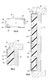
- FIG. 1 is a front perspective view of a window protection system according to the present invention including a shaping member and a supply system for filling the shaping member with a fluidic compressible material which hardens to form a solidified compressible material.
- FIG. 2 is a side sectional view of a compressible structure formed when the shaping member of FIG. 1 is filled with solidified compressible material.
- FIG. 3 is a front perspective view of an alternative supply system for the window protection system.
- FIG. 4 is a front perspective view of the compressible structure of FIG. 2 being positioned over the exterior of a glass pane of a window structure in a building.
- FIG. 5 is a front perspective view of the shaping member of FIG. 1 positioned over the exterior of a glass pane of a window structure in a building and being filled with a fluidic compressible material to form the compressible structure in situ.
- FIG. 6 is a side sectional view showing the compressible structure of FIG. 2 positioned over the interior of a glass pane of a window structure in a building and a modified compressible structure positioned over the exterior of the glass pane.
- FIG. 7 is a fragmentary side sectional view of another modified compressible structure positioned over the exterior of a glass pane of a window structure.
- FIG. 8 is a fragmentary side sectional view of a further modified compressible structure positioned over the exterior of a glass pane of a window structure.
- FIG. 9 is a fragmentary side sectional view of an additional modified compressible structure positioned over the exterior of a glass pane of a window structure.
- FIG. 10 is a rear perspective view of an alternative shaping member.
- FIG. 11 is a side sectional view of yet another modified compressible structure obtained with the shaping member of FIG. 10 over the exterior of a glass pane of a window structure in a building.
- FIG. 12 is a fragmentary side sectional view of yet a further modified compressible structure disposed over the exterior of a glass pane of a window structure.
- FIG. 13 is a front perspective view of still another modified compressible structure.
- FIG. 14 is a side sectional view of an additional modified compressible structure.
- FIG. 15 is a side sectional view illustrating formation of a further modified compressible structure.
- FIG. 16 is a front perspective view of the compressible structure of FIG. 13 positioned over the exterior of a glass pane of a window structure in a building.
- FIG. 17 is a front perspective view illustrating a plurality of compressible structures positioned over the exterior of a glass pane of a window structure in a building.
- FIG. 18 is a front perspective view of a compressible structure positioned over the exterior of a glass pane of a window structure in a building such as to be centered within a recess of the window structure.
- FIG. 19 is a front view showing expansion of a shaping member to different external sizes.
- FIG. 20 is an exploded perspective view of a securing device for the compressible structures according to the present invention.
- FIG. 21 is a broken side view illustrating insertion of a pin of the securing device through a compressible structure.
- FIG. 22 is a broken side view showing the pin releasably engaged with a clip of the securing device to removably attach the securing device to the compressible structures and illustrating removal of a backing sheet of the securing device to expose an adhesive.
- FIG. 23 is a broken side view, partly in section, illustrating the compressible structure releasably adhered to the exterior of a glass pane of a window structure via the adhesive of the securing device.
- FIG. 24 is a back view of the compressible structure with the securing device releasably attached thereto.
- the present invention relates to the positioning of a compressible structure over a glass window structure in a building in order to protect the window structure and the interior of the building from damage caused by high winds and wind-borne debris during storms.
- Buildings to which the invention applies may be both commercial and residential.
- the glass window structure can be of any conventional construction where one or more glass panes are held in place in a frame of one or multiple parts surrounding the one or more glass panes, such as sash windows, casement windows, slidably or pivotally movable windows and doors, non-movable windows, protruding windows and recessed windows.
- FIG. 1 illustrates a window protection system 10 according to the present invention including a shaping member or mold 12 and a supply system 14 for supplying a fluidic compressible material to shaping member 12 which hardens, cures, sets or solidifies to form a layer of solidified compressible material 20 thereby forming a compressible structure 16 as illustrated in FIG. 2.
- Shaping member 12 preferably has a perimetrical size to fit closely within a recess defined by the frame of a window structure or to overlap the frame some amount so as to cover one or more glass panes mounted within the frame.
- the shaping member 12 can be fabricated from various materials, such as paper, cardboard, cellulosic material, wood, polymer, metal and composite materials, with a flexible polymeric material being a preferred material.
- the shaping member 12 could also be fabricated from expandable or stretchable materials.
- the shaping member 12 is in the nature of a hollow membrane or body having a plurality of walls defining an interior cavity 18 for receiving or holding compressible material 20 as shown in FIG. 2.
- a back or rear wall 22 of shaping member 12 carries a securing element 24 by which the shaping member is removably secured over the one or more glass panes.
- the securing element 24 for compressible structure 16 includes a layer of adhesive 25 covering the outer surface of the back wall 22 partially or entirely and a protective cover sheet 26 disposed over the adhesive layer 25 prior to use.
- the cover sheet 26 is removable as shown in FIG. 2 to uncover or expose the adhesive layer 25 for attachment to the window structure as explained further below.
- a front wall 28 of the shaping member 12 faces exteriorly when the shaping member 12 is secured over the exterior of the one or more glass panes and thusly faces the storm for which the compressible structure 16 is to provide protection to the one or more glass panes.
- Opposing side walls 30 and top and bottom walls 32 extend between back wall 22 and front wall 28 and define a preselected depth for cavity 18 between back wall 22 and front wall 28 corresponding to a desired depth for the compressible material.
- the depth of cavity 18 will vary from 0.5 inch to 12 inches depending upon the size of the shaping member and the dimensions of the window structure to be protected.
- the walls of shaping member 12 are of sufficient thickness, rigidity and/or strength to shape and support the fluidic compressible material so that the layer of solidified compressible material 20 is positioned in front of the one or more glass panes and, preferably, in a plane parallel or substantially parallel to the plane of the one or more glass panes.
- a port 34 in shaping member 12 provides an opening into cavity 18 to allow the cavity to be filled with the fluidic compressible material.
- the port 34 for shaping member 12 is located in the front wall 28 near the upper right corner; however, the port 34 can be provided in any of the front, back, side, top or bottom walls at any suitable location to establish communication with the cavity 18 from externally of the shaping member. Where the shaping member 12 is to be filled with the fluidic compressible material prior to securement thereof over the one or more glass panes, the port 34 can be provided in any of the back, front, side, top or bottom walls.
- the port 34 typically would be provided in the front, side, top or bottom walls for ease of access and use. Shaping member 12 would typically be supplied in a flattened or collapsed condition prior to the compressible material being supplied to cavity 18 , and the unfilled shaping member can be folded to facilitate storage. Shaping member 12 is filled with the fluidic compressible material to obtain the compressible structure 16 , and the fluidic compressible material is supplied to cavity 18 via the port 34 .
- a desirable compressible material is a polymeric material or foam and, preferably, a polyurethane foam, because of the relatively light weight and effective cushioning and energy absorption properties of the solidified compressible material obtained therewith.
- Other polymeric foams can be utilized including high and low density foams of polyethylene, polypropylene and polyurethane and modified styrene foams, particularly high impact polystyrene foams modified with polybutadiene.
- Some examples of open cell, i.e. low density foams include polyether and polyester polyurethanes.
- closed cell foams examples include polyurethane, ethylene propylene diene monomer (EPDM), neoprene, styrene-butadiene copolymer rubber (SBR), nitrile-butadiene copolymer rubber (NBR), ethylene vinyl acetate (EVA), polyvinyl chloride (PVC) and (PVR/NBR). Additionally, crosslinked polyethylene, silicone and polystyrene foams and polyethylene can be used.
- the supply system 14 shown in FIG. 1, includes a supply tank 36 containing a quantity of the compressible material in fluidic form and having a delivery device 38 such as a discharge nozzle.
- the delivery device or nozzle 38 may be inserted into port 34 to allow for easy filling of cavity 18 with the fluidic compressible material.
- the fluidic compressible material may be sprayed into cavity 18 from the delivery device or, if the fluidic compressible material is too viscous to be sprayed or if the spray pressure is insufficient, the fluidic compressible material may be poured under pressure into cavity 18 from tank 36 .
- the fluidic compressible material is supplied to cavity 18 until the cavity is filled to a desired amount and, typically, the cavity will be completely filled.
- the delivery device or nozzle is removed from the port 34 , which will be closed by the compressible material or foam and is thusly self-sealing, since the fluidic compressible material or foam sets, cures, hardens or solidifies quickly to form the solidified compressible material 20 .
- the solidified compressible material preferably has twice as great compression strength in a direction parallel to the foam rise, i.e. perpendicular to back and front walls 22 and 28 , as compared with the compression strength in a direction perpendicular to the foam rise.
- the location of port 34 in front wall 28 ensures that the rise of the foam will generally be in a direction perpendicular to the back and front walls and, therefore, perpendicular to the one or more glass panes.
- compression strength and other physical strength characteristics will vary with the type of foaming system utilized. Compression strength values from 15 to 40 psi can be obtained with 2 lbs/ft 3 density urethane foams. A compression strength of 30 psi can be obtained with foam densities from 1.0 to 10.0 lbs/ft 3 . Many foams will be in the range of 5.0 lb/f 3 . With the variation in compression strength values related to density, a generalized correlation of strength with density can be obtained.
- a solidified compressible material formed from polyurethane or polyethylene foam provides increased energy absorption from projectiles as compared with a non-foam polymeric material due to the mechanical properties of the foam's cell or pore structure.
- the cells or pores preferably have diameters in the range of from 0.005 mm to 5.0 mm and, most preferably, in a range of from 0.01 mm to 0.03 mm and create a spongy three-dimensional, compressible, elastomeric web pattern with entrapped gas to absorb energy.
- the solidified compressible material formed from polyurethane or polyethylene foam preferably has a thickness within the shaping member, in a direction perpendicular to the one or more glass panes, in a range of from 0.5 inch to 12.0 inches corresponding to the depth of cavity 18 and, most preferably, in a range of from 1.0 to 4.0 inches to form an elastomeric, spongy cushion preventing shattering or fracturing of the underlying one or more glass panes.
- the depth of cavity 18 can be preselected to provide the desired thickness of polyurethane or polyethylene foam upon completion of the filling step, the fluidic polyurethane or polyethylene foam being shaped and supported by the shaping member to form a layer of solidified compressible material over the one or more glass panes.
- a one-component or two-component supply system may be utilized to fill cavity 18 with the fluidic compressible material.
- a one-component system is shown in FIG. 1, wherein tank 36 contains a fluidic compressible material including a polymeric blend such as a polymeric/polyol, polyurethane prepolymer and a polymeric hydrocarbon propellant to be delivered as a foam from delivery device 38 .
- a two-component supply system 114 is shown in FIG.
- a first supply tank 136 A contains component A, such as a polymeric polyol
- a second supply tank 136 B contains component B, such as disocyanate
- a mixing head 137 statically blends and reacts components A and B for delivery as a fluidic compressible material or foam through the delivery device or nozzle 138 .
- Components A and B can be housed in a single container 139 as shown in dotted lines.
- a catalyst may be added to either supply system to decrease or reduce the cure time.
- the supply system 114 can be provided without mixing head 137 , with component A being a first fluidic compressible material and component B being a second fluidic compressible material for selective discharge from the delivery device 138 to form a multi-layer compressible structure comprising multiple layers of first and second solidified compressible materials of different densities as described below.
- Compressible structure 16 i.e. shaping member 12 and solidified compressible material 20 , is releasably or removably secured over the one or more glass panes of the window structure, or the shaping member 12 is releasably or removably secured over the one or more glass panes of the window structure prior to being supplied with the fluidic compressible material which forms solidified compressible material 20 .
- FIG. 4 illustrates compressible structure 16 being positioned over the exterior surface of a glass pane 40 of a window structure 42 in a building. The glass pane 40 is surrounded and supported by a frame 44 of window structure 42 , and the glass pane 40 is disposed in a recess 43 circumscribed by the frame 44 .
- the compressible structure 16 wherein shaping member 12 has already been filled with the fluidic compressible material to form the layer of solidified compressible material 20 as described above and wherein the cover sheet 26 has been removed to expose the adhesive layer 25 , is positioned over the glass pane 40 to fit closely or snugly within the recess 43 .
- the compressible structure 16 is pressed firmly against the glass pane 40 so that the adhesive layer 25 contacts the exterior surface of the glass pane and releasably secures the compressible structure thereto to form a protected window structure.
- Filling the shaping member 12 with the fluidic compressible material prior to its securement over the glass pane allows the supply system to be kept in a central location rather than requiring its transport to numerous different locations where windows are to be protected.
- the shaping member could be filled at a remote location, for example at a warehouse, allowing a large number of compressible structures to be formed at one location.
- the compressible structure can be secured over the window structure a few minutes after filling the shaping member with the fluidic compressible material.
- An extendable arm or pole can be used to facilitate installation.
- the cover sheet 26 is removed to expose the adhesive layer 25 , and the shaping member 12 is pressed firmly against the exterior surface of a glass pane 140 prior to the shaping member being filled with the fluidic compressible material as shown in FIG. 5.
- the fluidic compressible material is then supplied to the cavity 18 via the delivery device or nozzle 38 of the supply system 14 inserted into port 34 as described above.
- the fluidic compressible material cures to form the layer of solidified compressible material 20 , thereby forming the compressible structure 16 in situ to form a protected window structure.
- FIG. 5 illustrates the shaping member 12 applied over a glass pane 140 which is not recessed within the frame 144 .
- the glass pane 140 has a perimeter slightly smaller than the perimeter of the shaping member 12 such that the shaping member overlaps the frame 144 a small amount. Accordingly, the adhesive layer 25 is pressed against the frame 144 where the shaping member overlaps the frame. In this manner, the shaping member 12 is releasably secured to the frame 144 as well as to the exterior surface of the glass pane 140 .
- the compressible structure 16 is deployed over the window structure to be protected in advance of the arrival of a storm.
- the layer of solidified compressible material absorbs energy and provides a shock absorption effect protecting the one or more glass panes from damage.
- the compressible structure prevents shattering of the one or more glass panes, provides an insulative effect, and protects the interior of the building.
- the compressible structure 16 can be easily removed from the window structure by detaching the adhesive layer 25 from the window structure.
- a compressible structure can be removed from the exterior side of the building; or, if the window structure is movable (e.g.
- the compressible structure can be removed from the interior side of the building without the use of a ladder by opening the window and pulling the compressible structure off the window structure and into the building. If the windows are not movable or do not open, an extension arm or pole can be used to remove the compressible structure.
- the compressible structure will normally be disposed of subsequent to use; however, the compressible structure could be retained for future re-use.
- the securing element should be capable of holding the compressible structure over the one or more glass panes during a storm yet should be easily detachable from the window structure after the storm has passed.
- a pressure sensitive adhesive is utilized as the securing element as illustrated for compressible structure 16
- the adhesive should provide sufficient holding strength for the compressible structure yet should be detachable from the window structure without excessive force. It is also desirable that the adhesive leave little or no residue on the window structure, particularly residue that is difficult to remove.
- the securing element need not be attached to or carried by the compressible structure prior to use in that the securing element can be provided separate from the compressible structure.
- securing elements can be utilized with the compressible structure including adhesives and/or mechanical securing devices such as clips. Where the securing element is an adhesive, the adhesive could be separately applied to the window structure and the compressible structure or shaping member can thereafter be secured thereto.
- the compressible structure 16 can be provided without a securing element, and a securing element, such as adhesive layer 125 , can be provided on the window structure as shown by dotted lines in FIG. 4.
- the adhesive layer 125 can be applied to all or part of the exterior surface of glass pane 40 , for example, to contact the compressible structure 16 or shaping member 12 when it is pressed against the glass pane. Additionally or alternatively, the adhesive layer 125 can be applied to one or more surfaces of frame 44 defining the recess 43 so as to be contacted by one or more of the side, top and or bottom walls of the compressible structure when it is positioned within the recess 43 . In the procedure illustrated by FIG.
- the adhesive layer 125 could be applied, for example, to the portion of frame 144 overlapped by the compressible structure 16 .
- the compressible material itself can serve as the securing element in that the fluidic compressible material or polymeric foam can be used to contact the window structure and adhere the compressible structure thereto as it solidifies or cures.
- FIG. 5 illustrates in dotted lines a cut-out or opening 145 in the back wall of shaping member 12 , in which case shaping member 12 may be provided without a securing element. The shaping member is manually held in place against the glass plane 140 as it is filled with the fluidic compressible material.
- the fluidic compressible material fills the cavity of the shaping member and rigidifies or cures, it contacts the glass pane and will become adhered thereto with sufficient force to hold the shaping member in place.
- the shaping member, and the resulting compressible structure can be provided with various different cut-outs or openings at various different locations on the shaping member to establish contact of the compressible material with the window structure, including the glass pane and/or frame, in order to adhere the shaping member thereto. Cut-outs or openings in the shaping member by which the compressible material adhesively contacts the window structure can be used in addition to a securing element for extra holding force.
- the adhesive properties of the foam can be adjusted and/or a release sheet or film can be applied to the window structure to facilitate removal of the compressible structure as disclosed in prior patent application Ser. No. 09/362,890 filed Jul. 29, 1999, and incorporated herein by reference.
- FIG. 6 shows a protected window structure formed by compressible structure 16 secured over an interior surface of a glass pane 40 of window structure 42 and a modified compressible structure 216 secured over window structure or can be formed prior to being positioned on the window structure as described above.
- FIG. 7 Another modified compressible structure is illustrated at 316 in FIG. 7, which illustrates compressible structure 316 secured over the exterior of glass pane 40 without a compressible structure being secured over the interior of glass pane 40 .
- Compressible structure 316 is similar to compressible structure 216 except for the construction of back wall 322 and front wall 328 .
- Back wall 322 is similar to back wall 222 and includes spaced layers 346 , with the adhesive layer 325 being carried by the layer 346 that is located on the back or outer side of the compressible structure.
- back wall 322 differs from back wall 222 in that polymeric particles 351 , such as styrene particles, are disposed between layers 346 and form the cushioning structure 347 .
- the front wall 328 differs from the front wall 228 in that the front wall 328 is made of the same material as the side, top and bottom walls of shaping member 312 .
- FIG. 8 illustrates at 416 a further alternative compressible structure secured over the exterior of glass pane 40 and having a back wall 422 which provides a cushioning effect.
- Compressible structure 416 is similar to compressible structure 316 except that the back wall 422 , which carrier adhesive layer 425 , is made of a layer of polymeric sponge material providing the cushioning effect between glass pane 40 and solidified compressible material 420 .
- FIG. 9 Another alternative compressible structure 516 is illustrated in FIG. 9 secured over the exterior of glass pane 40 .
- Compressible structure 516 is similar to compressible the exterior surface of glass pane 40 .
- Compressible structure 16 fits closely within the recess of frame 44 and is secured to the interior surface of glass pane 40 via adhesive layer 25 contacting the interior surface of glass pane 40 in the manner described above.
- Compressible structure 216 is similar to compressible structure 16 except that the front wall 228 of shaping member 212 is made of a relatively higher strength material, and the back wall 222 thereof is designed to provide a cushioning effect between glass pane 40 and the solidified compressible material 220 .
- the front wall 228 is made of a material having a higher tensile strength and higher impact and tear resistance than the materials used for the remaining walls of shaping member 212 .
- the back wall 222 is constructed from multiple spaced layers 246 , each preferably a layer of polymeric film such as polyethylene, polyurethane or polystyrene, and a cushioning structure 247 therebetween.
- the cushioning structure 247 is formed by a plurality of air cell units 250 between the layers 246 , and the adhesive layer 225 is carried by the layer 246 located on the outer or back side of the compressible structure.
- the back wall 222 is similar to the material known as “bubble wrap”, with the air cell units 250 varying in size from 0.001 inch to 12 inches.
- the air cell units 250 contain pockets of air and act as a protective cushion.
- the back wall 222 aids in separating the solidified compressible material, which absorbs the greatest force from impacts, from the glass pane 40 and acts as a protective cushion between the glass pane and the solidified compressible material.
- the back wall 222 also provides an insulative effect.
- the compressible structure 216 can be formed in situ on the structure 16 except that compressible structure 516 includes a cushioning element 552 interposed between back wall 522 and adhesive layer 525 .
- Cushioning element 552 is contiguous with back wall 522 and includes spaced layers 546 with a cushioning structure comprising polymeric particles 551 therebetween as described for back wall 322 .
- the cushioning element 552 can alternatively be constructed as a layer of polymeric sponge as described and illustrated for back wall 422 or as a plurality of layers of polymeric material having air cell units therebetween as described and illustrated for back wall 222 .
- FIG. 10 An alternative shaping member 612 is illustrated in FIG. 10 and differs from shaping member 12 primarily in that the shaping member 612 is provided without a back wall.
- Shaping member 612 is prefabricated or pre-built with interconnected side walls 630 and top and bottom walls 632 defining or circumscribing an opening 654 closed along one side by front wall 628 .
- the side, top and bottom walls are positioned to be oriented 90° to a window structure to which the shaping member 612 is to be temporarily secured.
- the side, top and bottom walls can be made of various materials including polymeric, paper, cardboard, various cellulosic materials, wood, metal, or composite materials.
- the front wall 628 is a polymeric film and, desirably, a high tensile strength polymeric film.
- the shaping member 612 can be constructed with various shapes and sizes in accordance with the shape and size of a window structure to be protected. The width of the side, top and bottom walls can be selected to correspond to a desired depth for the solidified compressible material within shaping member 612 .
- the shaping member 612 is used by positioning it over a window structure as shown in FIG. 11, which illustrates the shaping member 612 positioned within a recess of window structure 42 so as to be disposed over the exterior of glass pane 40 .
- the shaping member 612 has a perimetrical size corresponding to the size of the recess of window structure 42 and thus fits snugly or closely within the recess.
- the shaping member 612 is removably attached to the window structure via a securing element 624 including an adhesive layer 625 applied along the surfaces of frame 44 circumscribing the recess. Accordingly, the adhesive layer 625 contacts and adheres to the side, top and bottom walls of the shaping member 612 within the recess.
- the shaping member 612 is positioned in the recess so that the exterior surface of the glass pane 40 contacts the rearward edges of the side, top and bottom walls and thereby closes the opening 654 and forms a cavity 618 .
- a release sheet or film 656 can be applied over the exterior surface of glass pane 40 prior to positioning the shaping member 612 thereon, such a release sheet or film being described in the prior application incorporated herein by reference.
- the compressible structure 616 will typically be deployed in advance of a storm and, after the storm passes, the compressible structure 616 is removed from the window structure 42 .
- a further alternative shaping member is illustrated in FIG. 12 at 712 .
- the shaping member 712 is similar to the shaping member 612 except that the side, top and bottom walls of shaping member 712 have an L-shaped configuration defining a peripheral rim or lip 758 which can be placed against the window frame 44 .
- the lip 758 can be secured to the window frame 44 by a securing element, such as an adhesive layer 725 between the lip 758 and a front surface of the frame 44 .
- the shaping member 712 can be provided with the adhesive layer 725 pre-applied thereon and covered by a removable cover sheet as described above.
- the adhesive layer 725 can be applied to the lip 758 and/or frame 44 as part of the procedure to install the shaping member 712 on the window structure.
- the cavity 718 created by the shaping member 712 and the window structure is filled with the fluidic compressible material to form the layer of solidified compressible material 720 , thereby forming compressible structure 716 .
- the lip 758 does not have to be attached to the frame 44 but, rather, can be attached to the glass pane 40 or to a release film previously applied to the glass pane.
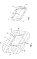
- FIG. 13 An alternative compressible structure 816 is illustrated in FIG. 13 and is a pre-formed, pre-fabricated foam panel providing a layer of solidified compressible material 820 , the back surface of which can be provided with an adhesive layer 825 by which the foam panel can be secured to a window structure to protect one or more glass panes thereof from damage. As shown by a dotted line 860 , the pre-shaped panel 816 can be cut to fit various shapes and sizes of windows.
- FIG. 14 illustrates an additional alternative compressible structure 916 , which is similar to compressible structure 816 except that the layer of solidified compressible material defining the foam panel comprises a plurality of layers of solidified compressible materials of different densities.
- Compressible structure 916 includes an outer or first layer 962 of a first solidified compressible material 920 A and an inner or second layer 964 of a second solidified compressible material 920 B, the outer and inner layers being laminated or bonded together.
- the first solidified compressible material 920 A is preferably a closed cell foam material of relatively greater density, fewer open pores and, therefore, relatively greater rigidity.
- the second solidified compressible material 920 B is an open or closed cell foam material with a greater number of open pores and, therefore, less rigidity.
- the layers 962 and 964 can be laminated or bonded together in various ways.
- the layer 964 carries an adhesive layer 925 covered by a releaseable cover sheet 926 .
- the more rigid foam layer 962 faces the storm and is exposed to the greatest impact from flying debris and wind.
- the less rigid foam layer 964 is disposed between the layer 962 of greater rigidity and the glass pane and provides a cushioning effect between the more rigid layer and the glass pane.
- FIG. 15 is illustrative of a procedure for filling a shaping member 1012 with first and second fluidic compressible materials to obtain first and second layers of first and second solidified compressible materials of different densities, respectively.
- FIG. 15 illustrates shaping member 1012 , which is similar to shaping member 12 , placed in a horizontal position wherein the shaping member will typically be supported on a table, the ground or other support surface.
- a supply system 1014 is used to deliver a first fluidic compressible material from a tank 1036 A to cavity 1018 via a delivery device or nozzle 1038 inserted in port 1034 , the first fluidic compressible material forming a first layer 1064 of a first solidified compressible material 1020 A of a first density.
- a second fluidic compressible material is supplied to the cavity from a tank 1036 B via the delivery device or nozzle 1038 inserted in port 1034 as shown in FIG. 15.
- the second fluidic compressible material is applied in a layer over the first compressible material until the cavity is filled and forms a layer 1062 of a second solidified compressible material 1020 B greater in density than the first solidified compressible material 1020 A.
- the delivery device or nozzle 1038 is similar to nozzle 38 except that the delivery device or nozzle 1038 is extendable for delivery of the fluidic compressible materials remote from the tanks 1036 A and 1036 B.
- FIG. 16 illustrates the compressible structure 816 secured over a glass pane of a window structure 42 to form a protected window structure using a securing element including one or more mechanical securing devices 865 in the form of spring clips inserted or interposed between the perimetrical edges, i.e. the external perimeter, of the compressible structure 816 and frame 44 .
- the securing devices 865 are spring biased to hold the compressible structure 816 in place on window structure 42 and are compressible to allow the compressible structure to be removed from the window structure.
- the mechanical securing devices may alternatively be designed as non-spring clips.
- FIG. 17 illustrates a protected window structure formed by a plurality of compressible structures 16 arranged over a glass pane of window structure 42 so that the entire surface area of the glass pane is covered by the plurality of compressible structures.
- FIG. 18 illustrates a compressible structure 1116 secured over a glass pane of a window structure 42 using a plurality of alternative mechanical securing devices 1165 .
- the compressible structure 1116 is similar to compressible structure 816 , but is smaller in peripheral or perimetrical size than the recess 43 of window structure 42 .
- the compressible structure 1116 is centered within recess 43 and is removably held in place over the glass pane by the securing devices 1165 .
- the securing devices 1165 are interposed between frame 44 and the side, top and bottom walls of compressible structure 1116 .
- the securing devices 1165 are extendable and retractable in a longitudinal direction to span the gap between the perimeter of the compressible structure 1116 and the frame 44 and tightly hold the compressible structure in place.
- the securing devices 1165 are shown without a spring bias but may be designed to incorporate an outward spring bias in the longitudinal direction.
- FIG. 19 illustrates the shaping member 1212 and, therefore, compressible structure 1216 obtained therewith, having a first external size when filled with a quantity of compressible material and illustrates the shaping member 1212 and, therefore, the compressible structure 1216 , having a second external size, greater than the first external size, when filled with a greater quantity of the compressible material.
- the shaping member is made of a flexible but inelastic material, any excess material not filled with compressible material can be folded over the layer of solidified compressible material.
- FIG. 20 illustrates an alternative securing device 1365 , one or more of which can be used as a securing element for the compressible structures of the present invention.
- Securing device 1365 includes an attachment member 1368 for attachment to a compressible structure and a clip 1370 for retaining the attachment member on the compressible structure.
- the attachment member 1368 includes a planar base 1371 and an elongate pin 1372 extending perpendicularly from the forward face of base 1371 .
- a rearward face of base 1371 carries a layer of pressure sensitive adhesive 1373 optionally covered by a removable backing sheet or liner 1374 .
- the base 1371 is preferably of minimal thickness to lay flat against the compressible structure and is shown as being circular in external configuration, but can be of any desired external shape.
- Pin 1372 has a length greater than the thickness of the compressible structure with which the securing device 1365 is to be used so that a forward end of pin 1372 protrudes from the compressible structure when the attachment member 1368 is attached thereto as explained further below.
- the forward end of pin 1372 tapers to a point to facilitate penetration of the compressible structure by the attachment member.
- the base and pin can be made of the same material or different materials, which may include metal, wood, polymer and fiber.
- Clip 1370 can be designed in various ways to retain the attachment member on the compressible structure and is shown as having an opening 1375 for slidably receiving the forward end of pin 1372 therethrough and retaining members or legs 1376 disposed around opening 1375 for releasably, lockingly engaging the forward end of pin 1372 passing through opening 1375 .
- the legs 1376 may be bent or angled and/or may be biased inwardly toward the center of opening 1375 to apply a locking force on pin 1372 . In the case of clip 1370 , the locking force is applied by the bent or angled portions of legs 1376 .
- legs 1376 may be manually squeezed or compressed to release the bent or angled portions from locking engagement with the pin 1372 , allowing the clip 1370 to be moved longitudinally along the pin 1372 and, when the legs are released, the legs lockingly engage the pin and prevent longitudinal movement of the clip relative thereto.
- FIGS. 21 - 23 illustrate use of securing device 1365 to secure a compressible structure over a glass pane of a window structure.
- FIG. 21 illustrates the clip 1370 removed from pin 1372 and shows the pin 1372 being inserted through a compressible structure 1316 .
- Compressible structure 1316 is similar to compressible structure 816 and is a pre-formed, pre-fabricated foam panel.
- the securing device 1365 can be used with the other compressible structures described herein.
- the pin 1372 is inserted, forward end first, through the back surface of the compressible structure and is advanced through the compressible structure in a perpendicular direction, with the pointed end of pin 1372 facilitating penetration of the compressible structure by the pin.
- the clip 1370 is assembled to the attachment member 1368 .
- the clip 1370 is placed over the forward end of pin 1372 so that the forward end passes through the opening 1375 .
- the clip 1370 is moved longitudinally along the pin 1372 in the direction of the compressible structure and, if necessary, the legs 1376 may be squeezed or compressed toward one another to facilitate longitudinal movement of the clip along the pin.
- the legs 1376 are released, and the bent or angled portions will lockingly engage the forward end of pin 1372 .
- the clip 1370 will then be in a locked position on pin 1372 such that the compressible structure 1316 is held between base 1371 and clip 1370 .
- the clip 1370 may be provided with a planar flange 1378 for abutting the forward surface of compressible structure 1316 so that the compressible structure is held between the planar flange 1378 and the planar base 1371 as shown in FIG. 22.
- the backing sheet 1374 is removed or peeled away from base 1371 to expose the layer of adhesive 1373 as shown in FIG. 22.
- the back surface of the compressible structure can be coated with an adhesive as shown by adhesive coating 1380 in FIG. 22.
- the adhesive coating 1380 is preferably a pressure sensitive adhesive weaker than the pressure sensitive adhesive 1373 and serves to bond the compressible structure to the glass pane for additional securing power and also creates a damping effect.
- the clip 1370 is withdrawn from pin 1372 .
- Withdrawal of the clip 1370 from the pin 1372 may be accomplished by squeezing the legs 1376 and sliding the clip along the pin in a direction away from the compressible structure 1316 until the pin is removed from the opening 1375 .
- the compressible structure 1316 may then be grasped and moved or pulled away from the glass pane 1340 in a direction perpendicular thereto so that the compressible structure is also removed entirely from the pin 1372 .
- the attachment member 1368 can now be removed from the glass pane by pulling an edge of base 1371 to release adhesive 1373 from its bond with the glass pane.
- Removal of base 1371 may be facilitated by using a razor blade or a solvent, if needed.
- the compressible structure can be stored for reuse.
- the securing device 1365 will typically be disposed of, and one or more new securing devices may be used in the future to secure the compressible structure 1316 to the glass pane of a window structure.
- one or more securing devices 1365 may be used to secure the compressible structure to the glass pane.
- the number of securing devices 1365 needed may also depend on the size of the securing devices.
- the base 1371 may be provided in various external sizes, for example, ranging from one inch to twelve inches in diameter.
- FIG. 24 shows the back surface of compressible structure 1316 with the base 1371 of the attachment member 1368 for the securing device being disposed at a central location on the compressible structure. As shown by bases 1371 in dotted lines, additional securing devices can be assembled to the compressible structure 1316 at other desired locations.
- Various adhesives can be used in the present invention, examples of which include polyurethane, cyanoacrylate, acrylate, epoxy, silicone, films, polyesters, rubber, hot melt polyolefins, polyamide, block copolymers, polyvinyl acetate, and vinyl acetate ethylene.
- Various release agents may be used to facilitate removal of the compressible structures from the window structures, and examples of such release agents include petroleum based substances, alcohols, aliphatic hydrocarbons, aromatic hydrocarbons, halogenated solvents, glycol ethers, methyl ethyl ketone, xylene, d-limonene, phthalate and benzoates.
- catalysts which may be used in the present invention to speed up reaction and/or curing times include amine catalysts, organometallic, bismuth and zinc organics.
Landscapes
- Engineering & Computer Science (AREA)
- Structural Engineering (AREA)
- Architecture (AREA)
- Civil Engineering (AREA)
- Securing Of Glass Panes Or The Like (AREA)
Abstract
A compressible structure for temporarily protecting a glass pane of a window structure includes a shaping member for removable securement on the window structure and defining a cavity over the glass pane and a layer of solidified compressible material in said cavity providing protection for the glass pane. A window protection system includes a shaping member and a supply system for supplying a compressible material in fluidic form to a cavity of the shaping member, wherein the fluidic compressible material sets to form a layer of solidified compressible material. A protected window structure comprises a window structure and a panel of solidified compressible foam material disposed over at least a portion of one or more glass panes of the window structure.
Description
- This application is related to prior U.S. patent application Ser. No. 09/362,890 filed Jul. 29, 1999, the disclosure of which is incorporated herein by reference.
- 1. Field of the Invention
- The present invention relates to protection of glass panes during storm conditions and, more particularly, to structures positioned over glass panes to absorb forces from high winds and wind-borne debris to protect the glass panes from shattering and damage.
- 2. Discussion of the Prior Art
- Protection of glass panes in buildings during storms has been a great problem in the past, and many efforts have been made to prevent the glass panes from shattering and falling into the building due to high winds, projectiles and debris thereby damaging the interior of the building due to the glass and due to wind and rain damage through the breached glass pane. Prior art attempts to protect glass panes in buildings from storm damage have included prefabricated storm shutters, plywood sheets, lamination systems and taping. Storm shutters are normally made of aluminum or other lightweight metal alloys, fiberglass, polyvinyl acrylate or other plastic. Storm shutters are fabricated to fit the exact measurements of window structures, including glass panes, to be protected and have the disadvantages of being expensive and requiring substantial time for fabrication such that storm shutters are not available unless ordered well in advance of a storm. Plywood sheets are generally sold in four-foot by eight-foot sheets with a thickness of ⅝ inch such that the plywood sheets weigh approximately 50 pounds each. The plywood sheets must be cut to fit the size of the window structures and are normally drilled and screwed into the building or window frame requiring craftsmanship, labor and hardware and, thus, having the disadvantages of being expensive and requiring substantial time to cover windows when a storm is approaching as well as being extremely heavy. Lamination systems, such as those supplied by 3M Corporation (e.g. Scotchshield) have the disadvantages of being films applied to the interior of the glass panes since they are designed to prevent shattered glass from collapsing to thereby prevent rain damage and glass fragments from becoming projectiles. The film is not particularly effective in preventing the glass from shattering and does not make the glass more shatter resistant. Since the film is usually on the interior of the glass, it cannot absorb enough energy from the glass fast enough to prevent a failure or fracture of the glass if the glass pane is struck by debris or projectiles. Accordingly, the primary use of lamination systems is to prevent shattered glass from falling apart. Taping of windows results, at best, in the holding of most of a fractured glass pane in place to reduce rain damage and the risk of individuals being cut.
- U.S. Pat. No. 3,830,760 to Benngston and U.S. Pat. No. 4,596,725 to Kluth et al are exemplary of polyurethane foams and discuss one-component and two-component polyurethanes. U.S. Pat. No. 3,455,865 to Bolt et al, U.S. Pat. No. 3,486,918 to Motter, U.S. Pat. No. 4,636,543 to Helton, U.S. Pat. No. 5,020,288 to Swenson, U.S. Pat. No. 5,107,643 to Swenson, U.S. Pat. No. 5,143,949 to Grogan et al, U.S. Pat. No. 5,186,978 to Woodhall et al, U.S. Pat. No. 5,281,436 to Swidler, U.S. Pat. No. 5,302,413 to Woodhall et al, U.S. Pat. No. 5,362,786 to Woodhall et al, U.S. Pat. No. 5,411,760 to Woodhall et al and U.S. Pat. No. 5,523,117 to Woodhall et al, are representative of polymeric films or layers for glass and/or polymeric films or layers removable by peeling.
- From the above, it will be appreciated that there is a great need for protection of glass panes in window structures installed in buildings due to storms where the protection can be quickly applied and is inexpensive while also being easily removed.
- Accordingly, it is an object of the present invention to provide protection for glass panes overcoming the abovementioned disadvantages of the prior art.
- Another object of the present invention is to protect glass panes in buildings from storm damage by temporarily positioning a compressible structure over a glass pane and, after the storm passes, removing the compressible structure.
- A further object of the present invention is to position a shaping member over a glass pane of a window structure in a building, wherein the shaping member is filled, prior to or subsequent to being positioned over the glass pane, with a fluidic compressible material which dries or cures to form a layer of solidified compressible material of sufficient thickness and properties to absorb energy from debris striking the shaping member during a storm.
- Another object of the present invention is to utilize a shaping member to shape a fluidic polymeric foam material applied over a glass pane of a window structure such that the fluidic compressible material hardens to form a layer of solidified compressible material temporarily protecting the glass pane from damage due to storms.
- An additional object of the present invention is to inflate a shaping member to a desired size in response to being filled, partially or entirely, with a fluidic compressible material which solidifies to form a compressible structure to protect a glass pane of a window structure in a building from storm damage.
- It is also an object of the present invention to utilize a glass pane of a window structure in a building to form a wall of a cavity defined over the glass pane for being supplied with a fluidic compressible material which solidifies to protect the glass pane from damage.
- The present invention has as a further object to position a plurality of compressible structures over a glass pane of a window structure in a building, with the plurality of compressible structures covering the surface area of the glass pane to protect the glass pane from damage due to storms.
- Yet another object of the present invention is to removably secure one or more pre-fabricated, polymeric foam panels over a glass pane of a window structure in a building to protect the glass pane from damage during storms.
- It is a further object of the present invention to provide a cushioning effect between a glass pane and a solidified compressible material disposed over the glass pane to protect against damage from storms.
- Still a further object of the present invention is to enhance the effectiveness of a compressible structure positioned over a glass pane of a window structure in a building to protect the glass pane from storm damage by utilizing a combination of solidified compressible materials of different densities in the compressible structure.
- Some of the advantages of the present invention are that the compressible structures protect glass panes from shattering during storms, the compressible material, where disposed within a shaping member, is protected from exposure to the elements, the compressible structures are easy to apply and remove, the compressible structures typically weigh much less than plywood or similar materials conventionally utilized to cover window structures, a two-component supply system for the fluidic compressible material provides long shelf life for easy and instant use at a moment's notice, the compressible structures can be installed by one person and will not lose their shape or protective qualities during long periods of exposure to the elements, the shaping members can be filled with the fluidic compressible material at one or a few locations so that the supply system for the fluidic compressible material need not be moved to the site of each window structure, the shaping member can be formed of flexible or collapsible materials to occupy minimal space for storage when not filled with the compressible material, the compressible structures can be releasably secured on window structures in various ways including adhesively and/or mechanically, the compressible material itself can be used to releasably adhere the compressible structures to the glass panes, securing mechanisms including Velcro or similar materials can be used to releasably secure the compressible structures on the window structures, and the fluidic compressible material can be sprayed or poured into the shaping member for ease of use.
- These and other objects, advantages and benefits are realized with the present invention as generally characterized in a compressible structure for temporarily protecting a window structure and comprising a shaping member for removable securement on the window structure and defining a cavity over one or more glass panes of the window structure, and a solidified compressible material in the cavity providing a protective layer over the one or more glass panes.
- The present invention is also generally characterized in a window protection system comprising a shaping member for removable securement on a window structure and defining a cavity over one or more glass panes of the window structure, a port in the shaping member providing an opening into the cavity and a supply system for supplying a fluidic compressible material to the cavity which solidifies or hardens to form a layer of solidified compressible material over the one or more glass panes. The shaping member and solidified compressible material form a compressible structure protecting the one or more glass panes.
- The present invention is further generally characterized in a temporarily protected window structure comprising a window structure and a compressible structure removably secured on the window structure. The compressible structure includes a layer of solidified compressible foam material disposed over one or more glass panes of the window structure to protect the one or more glass panes from damage. The layer of solidified compressible material may include a single layer or multiple layers of solidified compressible materials of different densities.
- Other objects and advantages of the present invention will become apparent from the following description of the preferred embodiments taken in conjunction with the accompanying drawings wherein like parts in each of the several figures are identified by the same reference characters.
- FIG. 1 is a front perspective view of a window protection system according to the present invention including a shaping member and a supply system for filling the shaping member with a fluidic compressible material which hardens to form a solidified compressible material.
- FIG. 2 is a side sectional view of a compressible structure formed when the shaping member of FIG. 1 is filled with solidified compressible material.
- FIG. 3 is a front perspective view of an alternative supply system for the window protection system.
- FIG. 4 is a front perspective view of the compressible structure of FIG. 2 being positioned over the exterior of a glass pane of a window structure in a building.
- FIG. 5 is a front perspective view of the shaping member of FIG. 1 positioned over the exterior of a glass pane of a window structure in a building and being filled with a fluidic compressible material to form the compressible structure in situ.
- FIG. 6 is a side sectional view showing the compressible structure of FIG. 2 positioned over the interior of a glass pane of a window structure in a building and a modified compressible structure positioned over the exterior of the glass pane.
- FIG. 7 is a fragmentary side sectional view of another modified compressible structure positioned over the exterior of a glass pane of a window structure.
- FIG. 8 is a fragmentary side sectional view of a further modified compressible structure positioned over the exterior of a glass pane of a window structure.
- FIG. 9 is a fragmentary side sectional view of an additional modified compressible structure positioned over the exterior of a glass pane of a window structure.
- FIG. 10 is a rear perspective view of an alternative shaping member.
- FIG. 11 is a side sectional view of yet another modified compressible structure obtained with the shaping member of FIG. 10 over the exterior of a glass pane of a window structure in a building.
- FIG. 12 is a fragmentary side sectional view of yet a further modified compressible structure disposed over the exterior of a glass pane of a window structure.
- FIG. 13 is a front perspective view of still another modified compressible structure.
- FIG. 14 is a side sectional view of an additional modified compressible structure.
- FIG. 15 is a side sectional view illustrating formation of a further modified compressible structure.
- FIG. 16 is a front perspective view of the compressible structure of FIG. 13 positioned over the exterior of a glass pane of a window structure in a building.
- FIG. 17 is a front perspective view illustrating a plurality of compressible structures positioned over the exterior of a glass pane of a window structure in a building.
- FIG. 18 is a front perspective view of a compressible structure positioned over the exterior of a glass pane of a window structure in a building such as to be centered within a recess of the window structure.
- FIG. 19 is a front view showing expansion of a shaping member to different external sizes.
- FIG. 20 is an exploded perspective view of a securing device for the compressible structures according to the present invention.
- FIG. 21 is a broken side view illustrating insertion of a pin of the securing device through a compressible structure.
- FIG. 22. is a broken side view showing the pin releasably engaged with a clip of the securing device to removably attach the securing device to the compressible structures and illustrating removal of a backing sheet of the securing device to expose an adhesive.
- FIG. 23 is a broken side view, partly in section, illustrating the compressible structure releasably adhered to the exterior of a glass pane of a window structure via the adhesive of the securing device.
- FIG. 24 is a back view of the compressible structure with the securing device releasably attached thereto.
- The present invention relates to the positioning of a compressible structure over a glass window structure in a building in order to protect the window structure and the interior of the building from damage caused by high winds and wind-borne debris during storms. Buildings to which the invention applies may be both commercial and residential. The glass window structure can be of any conventional construction where one or more glass panes are held in place in a frame of one or multiple parts surrounding the one or more glass panes, such as sash windows, casement windows, slidably or pivotally movable windows and doors, non-movable windows, protruding windows and recessed windows.
- FIG. 1 illustrates a
window protection system 10 according to the present invention including a shaping member ormold 12 and asupply system 14 for supplying a fluidic compressible material to shapingmember 12 which hardens, cures, sets or solidifies to form a layer of solidifiedcompressible material 20 thereby forming acompressible structure 16 as illustrated in FIG. 2. Shapingmember 12 preferably has a perimetrical size to fit closely within a recess defined by the frame of a window structure or to overlap the frame some amount so as to cover one or more glass panes mounted within the frame. The shapingmember 12 can be fabricated from various materials, such as paper, cardboard, cellulosic material, wood, polymer, metal and composite materials, with a flexible polymeric material being a preferred material. Use of a flexible material allows the shapingmember 12 to be flattened, collapsed and/or folded to occupy minimum space for storage prior to being filled with the compressible material and to allow for size adjustment when the shaping member is filled with the compressible material as explained further below. The shapingmember 12 could also be fabricated from expandable or stretchable materials. - The shaping
member 12 is in the nature of a hollow membrane or body having a plurality of walls defining aninterior cavity 18 for receiving or holdingcompressible material 20 as shown in FIG. 2. A back orrear wall 22 of shapingmember 12 carries a securingelement 24 by which the shaping member is removably secured over the one or more glass panes. The securingelement 24 forcompressible structure 16 includes a layer of adhesive 25 covering the outer surface of theback wall 22 partially or entirely and aprotective cover sheet 26 disposed over theadhesive layer 25 prior to use. Thecover sheet 26 is removable as shown in FIG. 2 to uncover or expose theadhesive layer 25 for attachment to the window structure as explained further below. Afront wall 28 of the shapingmember 12 faces exteriorly when the shapingmember 12 is secured over the exterior of the one or more glass panes and thusly faces the storm for which thecompressible structure 16 is to provide protection to the one or more glass panes. Opposingside walls 30 and top andbottom walls 32 extend betweenback wall 22 andfront wall 28 and define a preselected depth forcavity 18 betweenback wall 22 andfront wall 28 corresponding to a desired depth for the compressible material. Typically, the depth ofcavity 18 will vary from 0.5 inch to 12 inches depending upon the size of the shaping member and the dimensions of the window structure to be protected. The walls of shapingmember 12 are of sufficient thickness, rigidity and/or strength to shape and support the fluidic compressible material so that the layer of solidifiedcompressible material 20 is positioned in front of the one or more glass panes and, preferably, in a plane parallel or substantially parallel to the plane of the one or more glass panes. - A
port 34 in shapingmember 12 provides an opening intocavity 18 to allow the cavity to be filled with the fluidic compressible material. Theport 34 for shapingmember 12 is located in thefront wall 28 near the upper right corner; however, theport 34 can be provided in any of the front, back, side, top or bottom walls at any suitable location to establish communication with thecavity 18 from externally of the shaping member. Where the shapingmember 12 is to be filled with the fluidic compressible material prior to securement thereof over the one or more glass panes, theport 34 can be provided in any of the back, front, side, top or bottom walls. Where the shapingmember 12 is to be filled with the fluidic compressible material after the shapingmember 12 is secured over the one or more glass panes, theport 34 typically would be provided in the front, side, top or bottom walls for ease of access and use. Shapingmember 12 would typically be supplied in a flattened or collapsed condition prior to the compressible material being supplied tocavity 18, and the unfilled shaping member can be folded to facilitate storage. Shapingmember 12 is filled with the fluidic compressible material to obtain thecompressible structure 16, and the fluidic compressible material is supplied tocavity 18 via theport 34. - A desirable compressible material is a polymeric material or foam and, preferably, a polyurethane foam, because of the relatively light weight and effective cushioning and energy absorption properties of the solidified compressible material obtained therewith. Other polymeric foams can be utilized including high and low density foams of polyethylene, polypropylene and polyurethane and modified styrene foams, particularly high impact polystyrene foams modified with polybutadiene. Some examples of open cell, i.e. low density foams, include polyether and polyester polyurethanes. Examples of closed cell foams include polyurethane, ethylene propylene diene monomer (EPDM), neoprene, styrene-butadiene copolymer rubber (SBR), nitrile-butadiene copolymer rubber (NBR), ethylene vinyl acetate (EVA), polyvinyl chloride (PVC) and (PVR/NBR). Additionally, crosslinked polyethylene, silicone and polystyrene foams and polyethylene can be used.
- The
supply system 14, shown in FIG. 1, includes asupply tank 36 containing a quantity of the compressible material in fluidic form and having adelivery device 38 such as a discharge nozzle. The delivery device ornozzle 38 may be inserted intoport 34 to allow for easy filling ofcavity 18 with the fluidic compressible material. The fluidic compressible material may be sprayed intocavity 18 from the delivery device or, if the fluidic compressible material is too viscous to be sprayed or if the spray pressure is insufficient, the fluidic compressible material may be poured under pressure intocavity 18 fromtank 36. The fluidic compressible material is supplied tocavity 18 until the cavity is filled to a desired amount and, typically, the cavity will be completely filled. Once the cavity is filled, the delivery device or nozzle is removed from theport 34, which will be closed by the compressible material or foam and is thusly self-sealing, since the fluidic compressible material or foam sets, cures, hardens or solidifies quickly to form the solidifiedcompressible material 20. The solidified compressible material preferably has twice as great compression strength in a direction parallel to the foam rise, i.e. perpendicular to back andfront walls port 34 infront wall 28 ensures that the rise of the foam will generally be in a direction perpendicular to the back and front walls and, therefore, perpendicular to the one or more glass panes. The compression strength and other physical strength characteristics will vary with the type of foaming system utilized. Compression strength values from 15 to 40 psi can be obtained with 2 lbs/ft3 density urethane foams. A compression strength of 30 psi can be obtained with foam densities from 1.0 to 10.0 lbs/ft3. Many foams will be in the range of 5.0 lb/f3. With the variation in compression strength values related to density, a generalized correlation of strength with density can be obtained. - A solidified compressible material formed from polyurethane or polyethylene foam provides increased energy absorption from projectiles as compared with a non-foam polymeric material due to the mechanical properties of the foam's cell or pore structure. The cells or pores preferably have diameters in the range of from 0.005 mm to 5.0 mm and, most preferably, in a range of from 0.01 mm to 0.03 mm and create a spongy three-dimensional, compressible, elastomeric web pattern with entrapped gas to absorb energy. The solidified compressible material formed from polyurethane or polyethylene foam preferably has a thickness within the shaping member, in a direction perpendicular to the one or more glass panes, in a range of from 0.5 inch to 12.0 inches corresponding to the depth of
cavity 18 and, most preferably, in a range of from 1.0 to 4.0 inches to form an elastomeric, spongy cushion preventing shattering or fracturing of the underlying one or more glass panes. The depth ofcavity 18 can be preselected to provide the desired thickness of polyurethane or polyethylene foam upon completion of the filling step, the fluidic polyurethane or polyethylene foam being shaped and supported by the shaping member to form a layer of solidified compressible material over the one or more glass panes. - A one-component or two-component supply system may be utilized to fill
cavity 18 with the fluidic compressible material. A one-component system is shown in FIG. 1, whereintank 36 contains a fluidic compressible material including a polymeric blend such as a polymeric/polyol, polyurethane prepolymer and a polymeric hydrocarbon propellant to be delivered as a foam fromdelivery device 38. A two-component supply system 114 is shown in FIG. 3, wherein afirst supply tank 136A contains component A, such as a polymeric polyol, asecond supply tank 136B contains component B, such as disocyanate, and a mixinghead 137 statically blends and reacts components A and B for delivery as a fluidic compressible material or foam through the delivery device ornozzle 138. Components A and B can be housed in asingle container 139 as shown in dotted lines. A catalyst may be added to either supply system to decrease or reduce the cure time. Thesupply system 114 can be provided without mixinghead 137, with component A being a first fluidic compressible material and component B being a second fluidic compressible material for selective discharge from thedelivery device 138 to form a multi-layer compressible structure comprising multiple layers of first and second solidified compressible materials of different densities as described below. -
Compressible structure 16, i.e. shapingmember 12 and solidifiedcompressible material 20, is releasably or removably secured over the one or more glass panes of the window structure, or the shapingmember 12 is releasably or removably secured over the one or more glass panes of the window structure prior to being supplied with the fluidic compressible material which forms solidifiedcompressible material 20. FIG. 4 illustratescompressible structure 16 being positioned over the exterior surface of aglass pane 40 of awindow structure 42 in a building. Theglass pane 40 is surrounded and supported by aframe 44 ofwindow structure 42, and theglass pane 40 is disposed in arecess 43 circumscribed by theframe 44. Thecompressible structure 16, wherein shapingmember 12 has already been filled with the fluidic compressible material to form the layer of solidifiedcompressible material 20 as described above and wherein thecover sheet 26 has been removed to expose theadhesive layer 25, is positioned over theglass pane 40 to fit closely or snugly within therecess 43. Thecompressible structure 16 is pressed firmly against theglass pane 40 so that theadhesive layer 25 contacts the exterior surface of the glass pane and releasably secures the compressible structure thereto to form a protected window structure. Filling the shapingmember 12 with the fluidic compressible material prior to its securement over the glass pane allows the supply system to be kept in a central location rather than requiring its transport to numerous different locations where windows are to be protected. Also, the shaping member could be filled at a remote location, for example at a warehouse, allowing a large number of compressible structures to be formed at one location. The compressible structure can be secured over the window structure a few minutes after filling the shaping member with the fluidic compressible material. An extendable arm or pole can be used to facilitate installation. - Alternatively, the
cover sheet 26 is removed to expose theadhesive layer 25, and the shapingmember 12 is pressed firmly against the exterior surface of aglass pane 140 prior to the shaping member being filled with the fluidic compressible material as shown in FIG. 5. The fluidic compressible material is then supplied to thecavity 18 via the delivery device ornozzle 38 of thesupply system 14 inserted intoport 34 as described above. The fluidic compressible material cures to form the layer of solidifiedcompressible material 20, thereby forming thecompressible structure 16 in situ to form a protected window structure. FIG. 5 illustrates the shapingmember 12 applied over aglass pane 140 which is not recessed within theframe 144. Also, theglass pane 140 has a perimeter slightly smaller than the perimeter of the shapingmember 12 such that the shaping member overlaps the frame 144 a small amount. Accordingly, theadhesive layer 25 is pressed against theframe 144 where the shaping member overlaps the frame. In this manner, the shapingmember 12 is releasably secured to theframe 144 as well as to the exterior surface of theglass pane 140. - The
compressible structure 16 is deployed over the window structure to be protected in advance of the arrival of a storm. When the storm arrives, the layer of solidified compressible material absorbs energy and provides a shock absorption effect protecting the one or more glass panes from damage. The compressible structure prevents shattering of the one or more glass panes, provides an insulative effect, and protects the interior of the building. After the storm passes, thecompressible structure 16 can be easily removed from the window structure by detaching theadhesive layer 25 from the window structure. A compressible structure can be removed from the exterior side of the building; or, if the window structure is movable (e.g. pivotal or on tracks), the compressible structure can be removed from the interior side of the building without the use of a ladder by opening the window and pulling the compressible structure off the window structure and into the building. If the windows are not movable or do not open, an extension arm or pole can be used to remove the compressible structure. The compressible structure will normally be disposed of subsequent to use; however, the compressible structure could be retained for future re-use. - It should be appreciated that the securing element should be capable of holding the compressible structure over the one or more glass panes during a storm yet should be easily detachable from the window structure after the storm has passed. Where a pressure sensitive adhesive is utilized as the securing element as illustrated for
compressible structure 16, the adhesive should provide sufficient holding strength for the compressible structure yet should be detachable from the window structure without excessive force. It is also desirable that the adhesive leave little or no residue on the window structure, particularly residue that is difficult to remove. It should also be appreciated that the securing element need not be attached to or carried by the compressible structure prior to use in that the securing element can be provided separate from the compressible structure. Various securing elements can be utilized with the compressible structure including adhesives and/or mechanical securing devices such as clips. Where the securing element is an adhesive, the adhesive could be separately applied to the window structure and the compressible structure or shaping member can thereafter be secured thereto. - As an example of the above, the
compressible structure 16 can be provided without a securing element, and a securing element, such asadhesive layer 125, can be provided on the window structure as shown by dotted lines in FIG. 4. Theadhesive layer 125 can be applied to all or part of the exterior surface ofglass pane 40, for example, to contact thecompressible structure 16 or shapingmember 12 when it is pressed against the glass pane. Additionally or alternatively, theadhesive layer 125 can be applied to one or more surfaces offrame 44 defining therecess 43 so as to be contacted by one or more of the side, top and or bottom walls of the compressible structure when it is positioned within therecess 43. In the procedure illustrated by FIG. 5, theadhesive layer 125 could be applied, for example, to the portion offrame 144 overlapped by thecompressible structure 16. The compressible material itself can serve as the securing element in that the fluidic compressible material or polymeric foam can be used to contact the window structure and adhere the compressible structure thereto as it solidifies or cures. As an example, FIG. 5 illustrates in dotted lines a cut-out or opening 145 in the back wall of shapingmember 12, in whichcase shaping member 12 may be provided without a securing element. The shaping member is manually held in place against theglass plane 140 as it is filled with the fluidic compressible material. As the fluidic compressible material fills the cavity of the shaping member and rigidifies or cures, it contacts the glass pane and will become adhered thereto with sufficient force to hold the shaping member in place. Of course, the shaping member, and the resulting compressible structure, can be provided with various different cut-outs or openings at various different locations on the shaping member to establish contact of the compressible material with the window structure, including the glass pane and/or frame, in order to adhere the shaping member thereto. Cut-outs or openings in the shaping member by which the compressible material adhesively contacts the window structure can be used in addition to a securing element for extra holding force. Since the foam can be very adherent by nature, the adhesive properties of the foam can be adjusted and/or a release sheet or film can be applied to the window structure to facilitate removal of the compressible structure as disclosed in prior patent application Ser. No. 09/362,890 filed Jul. 29, 1999, and incorporated herein by reference. - Compressible structures could be placed over both the exterior surface and the interior surface of a glass pane for increased protection. FIG. 6 shows a protected window structure formed by
compressible structure 16 secured over an interior surface of aglass pane 40 ofwindow structure 42 and a modifiedcompressible structure 216 secured over window structure or can be formed prior to being positioned on the window structure as described above. - Another modified compressible structure is illustrated at 316 in FIG. 7, which illustrates
compressible structure 316 secured over the exterior ofglass pane 40 without a compressible structure being secured over the interior ofglass pane 40.Compressible structure 316 is similar tocompressible structure 216 except for the construction ofback wall 322 andfront wall 328. Backwall 322 is similar toback wall 222 and includes spacedlayers 346, with theadhesive layer 325 being carried by thelayer 346 that is located on the back or outer side of the compressible structure. However,back wall 322 differs fromback wall 222 in thatpolymeric particles 351, such as styrene particles, are disposed betweenlayers 346 and form thecushioning structure 347. Thefront wall 328 differs from thefront wall 228 in that thefront wall 328 is made of the same material as the side, top and bottom walls of shapingmember 312. - FIG. 8 illustrates at 416 a further alternative compressible structure secured over the exterior of
glass pane 40 and having aback wall 422 which provides a cushioning effect.Compressible structure 416 is similar tocompressible structure 316 except that theback wall 422, whichcarrier adhesive layer 425, is made of a layer of polymeric sponge material providing the cushioning effect betweenglass pane 40 and solidifiedcompressible material 420. - Another alternative
compressible structure 516 is illustrated in FIG. 9 secured over the exterior ofglass pane 40.Compressible structure 516 is similar to compressible the exterior surface ofglass pane 40.Compressible structure 16 fits closely within the recess offrame 44 and is secured to the interior surface ofglass pane 40 viaadhesive layer 25 contacting the interior surface ofglass pane 40 in the manner described above.Compressible structure 216 is similar tocompressible structure 16 except that thefront wall 228 of shapingmember 212 is made of a relatively higher strength material, and theback wall 222 thereof is designed to provide a cushioning effect betweenglass pane 40 and the solidifiedcompressible material 220. Thefront wall 228 is made of a material having a higher tensile strength and higher impact and tear resistance than the materials used for the remaining walls of shapingmember 212. Theback wall 222 is constructed from multiple spacedlayers 246, each preferably a layer of polymeric film such as polyethylene, polyurethane or polystyrene, and acushioning structure 247 therebetween. Thecushioning structure 247 is formed by a plurality ofair cell units 250 between thelayers 246, and the adhesive layer 225 is carried by thelayer 246 located on the outer or back side of the compressible structure. Theback wall 222 is similar to the material known as “bubble wrap”, with theair cell units 250 varying in size from 0.001 inch to 12 inches. Theair cell units 250 contain pockets of air and act as a protective cushion. In particular, theback wall 222 aids in separating the solidified compressible material, which absorbs the greatest force from impacts, from theglass pane 40 and acts as a protective cushion between the glass pane and the solidified compressible material. Theback wall 222 also provides an insulative effect. Thecompressible structure 216 can be formed in situ on thestructure 16 except thatcompressible structure 516 includes acushioning element 552 interposed betweenback wall 522 andadhesive layer 525. Cushioningelement 552 is contiguous withback wall 522 and includes spacedlayers 546 with a cushioning structure comprisingpolymeric particles 551 therebetween as described forback wall 322. Thecushioning element 552 can alternatively be constructed as a layer of polymeric sponge as described and illustrated forback wall 422 or as a plurality of layers of polymeric material having air cell units therebetween as described and illustrated forback wall 222. - An
alternative shaping member 612 is illustrated in FIG. 10 and differs from shapingmember 12 primarily in that the shapingmember 612 is provided without a back wall. Shapingmember 612 is prefabricated or pre-built withinterconnected side walls 630 and top andbottom walls 632 defining or circumscribing anopening 654 closed along one side byfront wall 628. The side, top and bottom walls are positioned to be oriented 90° to a window structure to which the shapingmember 612 is to be temporarily secured. The side, top and bottom walls can be made of various materials including polymeric, paper, cardboard, various cellulosic materials, wood, metal, or composite materials. Preferably, thefront wall 628 is a polymeric film and, desirably, a high tensile strength polymeric film. The shapingmember 612 can be constructed with various shapes and sizes in accordance with the shape and size of a window structure to be protected. The width of the side, top and bottom walls can be selected to correspond to a desired depth for the solidified compressible material within shapingmember 612. - The shaping
member 612 is used by positioning it over a window structure as shown in FIG. 11, which illustrates the shapingmember 612 positioned within a recess ofwindow structure 42 so as to be disposed over the exterior ofglass pane 40. The shapingmember 612 has a perimetrical size corresponding to the size of the recess ofwindow structure 42 and thus fits snugly or closely within the recess. The shapingmember 612 is removably attached to the window structure via a securingelement 624 including anadhesive layer 625 applied along the surfaces offrame 44 circumscribing the recess. Accordingly, theadhesive layer 625 contacts and adheres to the side, top and bottom walls of the shapingmember 612 within the recess. The shapingmember 612 is positioned in the recess so that the exterior surface of theglass pane 40 contacts the rearward edges of the side, top and bottom walls and thereby closes theopening 654 and forms acavity 618. FIG. 11, therefore, is illustrative of a procedure wherein the glass pane forms the back wall of and completes the cavity for receiving the fluidic compressible material. Once the shapingmember 612 is properly positioned over theglass pane 40, thecavity 618 is supplied with the fluidic compressible material to form the layer of solidifiedcompressible material 620 as described above thereby forming thecompressible structure 616. If desired, a release sheet orfilm 656, shown in dotted lines, can be applied over the exterior surface ofglass pane 40 prior to positioning the shapingmember 612 thereon, such a release sheet or film being described in the prior application incorporated herein by reference. Thecompressible structure 616 will typically be deployed in advance of a storm and, after the storm passes, thecompressible structure 616 is removed from thewindow structure 42. - A further alternative shaping member is illustrated in FIG. 12 at 712. The shaping
member 712 is similar to the shapingmember 612 except that the side, top and bottom walls of shapingmember 712 have an L-shaped configuration defining a peripheral rim orlip 758 which can be placed against thewindow frame 44. Thelip 758 can be secured to thewindow frame 44 by a securing element, such as anadhesive layer 725 between thelip 758 and a front surface of theframe 44. Of course, the shapingmember 712 can be provided with theadhesive layer 725 pre-applied thereon and covered by a removable cover sheet as described above. Alternatively, theadhesive layer 725 can be applied to thelip 758 and/orframe 44 as part of the procedure to install the shapingmember 712 on the window structure. Once the shapingmember 712 has been properly secured over theglass pane 40, thecavity 718 created by the shapingmember 712 and the window structure is filled with the fluidic compressible material to form the layer of solidifiedcompressible material 720, thereby formingcompressible structure 716. It should be appreciated that thelip 758 does not have to be attached to theframe 44 but, rather, can be attached to theglass pane 40 or to a release film previously applied to the glass pane. - An alternative
compressible structure 816 is illustrated in FIG. 13 and is a pre-formed, pre-fabricated foam panel providing a layer of solidifiedcompressible material 820, the back surface of which can be provided with anadhesive layer 825 by which the foam panel can be secured to a window structure to protect one or more glass panes thereof from damage. As shown by a dottedline 860, thepre-shaped panel 816 can be cut to fit various shapes and sizes of windows. - FIG. 14 illustrates an additional alternative
compressible structure 916, which is similar tocompressible structure 816 except that the layer of solidified compressible material defining the foam panel comprises a plurality of layers of solidified compressible materials of different densities.Compressible structure 916 includes an outer orfirst layer 962 of a first solidifiedcompressible material 920A and an inner or second layer 964 of a second solidifiedcompressible material 920B, the outer and inner layers being laminated or bonded together. The first solidifiedcompressible material 920A is preferably a closed cell foam material of relatively greater density, fewer open pores and, therefore, relatively greater rigidity. The second solidifiedcompressible material 920B is an open or closed cell foam material with a greater number of open pores and, therefore, less rigidity. Thelayers 962 and 964 can be laminated or bonded together in various ways. The layer 964 carries anadhesive layer 925 covered by areleaseable cover sheet 926. The morerigid foam layer 962 faces the storm and is exposed to the greatest impact from flying debris and wind. The less rigid foam layer 964 is disposed between thelayer 962 of greater rigidity and the glass pane and provides a cushioning effect between the more rigid layer and the glass pane. - FIG. 15 is illustrative of a procedure for filling a shaping
member 1012 with first and second fluidic compressible materials to obtain first and second layers of first and second solidified compressible materials of different densities, respectively. FIG. 15 illustrates shapingmember 1012, which is similar to shapingmember 12, placed in a horizontal position wherein the shaping member will typically be supported on a table, the ground or other support surface. Asupply system 1014 is used to deliver a first fluidic compressible material from atank 1036A tocavity 1018 via a delivery device ornozzle 1038 inserted inport 1034, the first fluidic compressible material forming afirst layer 1064 of a first solidifiedcompressible material 1020A of a first density. Once the first fluidic compressible material has been supplied to the cavity in a uniform or substantially uniform layer and has been allowed to set somewhat to form thefirst layer 1064 of first compressible solidified material 1020A, a second fluidic compressible material is supplied to the cavity from atank 1036B via the delivery device ornozzle 1038 inserted inport 1034 as shown in FIG. 15. The second fluidic compressible material is applied in a layer over the first compressible material until the cavity is filled and forms alayer 1062 of a second solidifiedcompressible material 1020B greater in density than the first solidifiedcompressible material 1020A. Of course, the first and second fluidic compressible materials can be contained in different supply systems. The delivery device ornozzle 1038 is similar tonozzle 38 except that the delivery device ornozzle 1038 is extendable for delivery of the fluidic compressible materials remote from thetanks - FIG. 16 illustrates the
compressible structure 816 secured over a glass pane of awindow structure 42 to form a protected window structure using a securing element including one or moremechanical securing devices 865 in the form of spring clips inserted or interposed between the perimetrical edges, i.e. the external perimeter, of thecompressible structure 816 andframe 44. The securingdevices 865 are spring biased to hold thecompressible structure 816 in place onwindow structure 42 and are compressible to allow the compressible structure to be removed from the window structure. The mechanical securing devices may alternatively be designed as non-spring clips. - FIG. 17 illustrates a protected window structure formed by a plurality of
compressible structures 16 arranged over a glass pane ofwindow structure 42 so that the entire surface area of the glass pane is covered by the plurality of compressible structures. - FIG. 18 illustrates a
compressible structure 1116 secured over a glass pane of awindow structure 42 using a plurality of alternativemechanical securing devices 1165. Thecompressible structure 1116 is similar tocompressible structure 816, but is smaller in peripheral or perimetrical size than therecess 43 ofwindow structure 42. Thecompressible structure 1116 is centered withinrecess 43 and is removably held in place over the glass pane by the securingdevices 1165. The securingdevices 1165 are interposed betweenframe 44 and the side, top and bottom walls ofcompressible structure 1116. The securingdevices 1165 are extendable and retractable in a longitudinal direction to span the gap between the perimeter of thecompressible structure 1116 and theframe 44 and tightly hold the compressible structure in place. The securingdevices 1165 are shown without a spring bias but may be designed to incorporate an outward spring bias in the longitudinal direction. - A
compressible structure 1216 that is adjustable in external size is illustrated in FIG. 19. Thecompressible structure 1216 is similar tocompressible structure 16 and is made of flexible material or of elastic or stretchable material such that the external size of the shapingmember 1212 can be adjusted or controlled by controlling the amount of fluidic compressible material supplied to the shapingmember 1212. FIG. 19 illustrates the shapingmember 1212 and, therefore,compressible structure 1216 obtained therewith, having a first external size when filled with a quantity of compressible material and illustrates the shapingmember 1212 and, therefore, thecompressible structure 1216, having a second external size, greater than the first external size, when filled with a greater quantity of the compressible material. Where the shaping member is made of a flexible but inelastic material, any excess material not filled with compressible material can be folded over the layer of solidified compressible material. - FIG. 20 illustrates an
alternative securing device 1365, one or more of which can be used as a securing element for the compressible structures of the present invention. Securingdevice 1365 includes anattachment member 1368 for attachment to a compressible structure and aclip 1370 for retaining the attachment member on the compressible structure. Theattachment member 1368 includes aplanar base 1371 and anelongate pin 1372 extending perpendicularly from the forward face ofbase 1371. As shown in FIG. 22, a rearward face of base 1371 carries a layer of pressure sensitive adhesive 1373 optionally covered by a removable backing sheet orliner 1374. Thebase 1371 is preferably of minimal thickness to lay flat against the compressible structure and is shown as being circular in external configuration, but can be of any desired external shape.Pin 1372 has a length greater than the thickness of the compressible structure with which thesecuring device 1365 is to be used so that a forward end ofpin 1372 protrudes from the compressible structure when theattachment member 1368 is attached thereto as explained further below. Preferably, the forward end ofpin 1372 tapers to a point to facilitate penetration of the compressible structure by the attachment member. The base and pin can be made of the same material or different materials, which may include metal, wood, polymer and fiber.Clip 1370 can be designed in various ways to retain the attachment member on the compressible structure and is shown as having anopening 1375 for slidably receiving the forward end ofpin 1372 therethrough and retaining members orlegs 1376 disposed around opening 1375 for releasably, lockingly engaging the forward end ofpin 1372 passing throughopening 1375. Thelegs 1376 may be bent or angled and/or may be biased inwardly toward the center of opening 1375 to apply a locking force onpin 1372. In the case ofclip 1370, the locking force is applied by the bent or angled portions oflegs 1376. The ends oflegs 1376 may be manually squeezed or compressed to release the bent or angled portions from locking engagement with thepin 1372, allowing theclip 1370 to be moved longitudinally along thepin 1372 and, when the legs are released, the legs lockingly engage the pin and prevent longitudinal movement of the clip relative thereto. - FIGS. 21-23 illustrate use of securing
device 1365 to secure a compressible structure over a glass pane of a window structure. FIG. 21 illustrates theclip 1370 removed frompin 1372 and shows thepin 1372 being inserted through acompressible structure 1316.Compressible structure 1316 is similar tocompressible structure 816 and is a pre-formed, pre-fabricated foam panel. However, it should be appreciated that thesecuring device 1365 can be used with the other compressible structures described herein. Thepin 1372 is inserted, forward end first, through the back surface of the compressible structure and is advanced through the compressible structure in a perpendicular direction, with the pointed end ofpin 1372 facilitating penetration of the compressible structure by the pin. Once thebase 1371 is in abutment with the back surface of thecompressible structure 1316 and the forward end ofpin 1372 protrudes from the forward surface of the compressible structure, theclip 1370 is assembled to theattachment member 1368. Theclip 1370 is placed over the forward end ofpin 1372 so that the forward end passes through theopening 1375. Theclip 1370 is moved longitudinally along thepin 1372 in the direction of the compressible structure and, if necessary, thelegs 1376 may be squeezed or compressed toward one another to facilitate longitudinal movement of the clip along the pin. Once theclip 1370 abuts the forward surface ofcompressible structure 1316, thelegs 1376 are released, and the bent or angled portions will lockingly engage the forward end ofpin 1372. Theclip 1370 will then be in a locked position onpin 1372 such that thecompressible structure 1316 is held betweenbase 1371 andclip 1370. As shown in FIG. 20, theclip 1370 may be provided with aplanar flange 1378 for abutting the forward surface ofcompressible structure 1316 so that the compressible structure is held between theplanar flange 1378 and theplanar base 1371 as shown in FIG. 22. Once a desired number of securingdevices 1365 has been assembled to the compressible structure, the compressible structure is ready to be secured over the glass pane of the window structure. To secure thecompressible structure 1316 over the glass pane of a window structure using thesecuring device 1365, thebacking sheet 1374 is removed or peeled away from base 1371 to expose the layer of adhesive 1373 as shown in FIG. 22. Optionally, the back surface of the compressible structure can be coated with an adhesive as shown byadhesive coating 1380 in FIG. 22. Theadhesive coating 1380 is preferably a pressure sensitive adhesive weaker than the pressure sensitive adhesive 1373 and serves to bond the compressible structure to the glass pane for additional securing power and also creates a damping effect. Once the adhesive 1373 is exposed by removingbacking sheet 1374, thecompressible structure 1316 is placed against theglass pane 1340 ofwindow structure 1372. FIG. 23 shows thecompressible structure 1316 positioned over the exterior ofglass pane 1340 and being secured thereto via the adhesive of base 1371 with theoptional adhesive coating 1380 providing additional holding force. - To remove the
compressible structure 1316 after a storm has passed, theclip 1370 is withdrawn frompin 1372. Withdrawal of theclip 1370 from thepin 1372 may be accomplished by squeezing thelegs 1376 and sliding the clip along the pin in a direction away from thecompressible structure 1316 until the pin is removed from theopening 1375. Thecompressible structure 1316 may then be grasped and moved or pulled away from theglass pane 1340 in a direction perpendicular thereto so that the compressible structure is also removed entirely from thepin 1372. Theattachment member 1368 can now be removed from the glass pane by pulling an edge of base 1371 to release adhesive 1373 from its bond with the glass pane. Removal of base 1371 may be facilitated by using a razor blade or a solvent, if needed. Upon removal of thecompressible structure 1316 from theattachment member 1368, the compressible structure can be stored for reuse. Thesecuring device 1365 will typically be disposed of, and one or more new securing devices may be used in the future to secure thecompressible structure 1316 to the glass pane of a window structure. - Depending on the external size of the compressible structure, one or
more securing devices 1365 may be used to secure the compressible structure to the glass pane. The number of securingdevices 1365 needed may also depend on the size of the securing devices. For instance, thebase 1371 may be provided in various external sizes, for example, ranging from one inch to twelve inches in diameter. FIG. 24 shows the back surface ofcompressible structure 1316 with thebase 1371 of theattachment member 1368 for the securing device being disposed at a central location on the compressible structure. As shown bybases 1371 in dotted lines, additional securing devices can be assembled to thecompressible structure 1316 at other desired locations. - Various adhesives can be used in the present invention, examples of which include polyurethane, cyanoacrylate, acrylate, epoxy, silicone, films, polyesters, rubber, hot melt polyolefins, polyamide, block copolymers, polyvinyl acetate, and vinyl acetate ethylene. Various release agents may be used to facilitate removal of the compressible structures from the window structures, and examples of such release agents include petroleum based substances, alcohols, aliphatic hydrocarbons, aromatic hydrocarbons, halogenated solvents, glycol ethers, methyl ethyl ketone, xylene, d-limonene, phthalate and benzoates. Examples of catalysts which may be used in the present invention to speed up reaction and/or curing times include amine catalysts, organometallic, bismuth and zinc organics.
- Inasmuch as the present invention is subject to various modifications and changes in detail, it should be appreciated that the preferred embodiments described herein should be considered as illustrative only and should not be taken in a limiting sense.
Claims (43)
1. A compressible structure for temporarily protecting a glass pane of a window structure comprising
a shaping member for removable securement on the window structure and defining a cavity over the glass pane; and
a layer of solidified compressible material in said cavity providing protection for the glass pane.
2. A compressible structure as recited in claim 1 and further including a port in said shaping member communicating with said cavity by which said compressible material is supplied to said cavity in fluidic form and solidifies within said cavity.
3. A compressible structure as recited in claim 2 wherein said compressible material is a polymeric foam.
4. A compressible structure as recited in claim 1 and further including a securing element for removably securing said compressible structure on the window structure.
5. A compressible structure as recited in claim 4 wherein said securing element includes a releaseable adhesive carried by said shaping member.
6. A compressible structure as recited in claim 4 wherein said compressible structure has an external perimeter and said securing element includes one or more securing devices interposed between said perimeter and the window structure.
7. A compressible structure as recited in claim 4 wherein said securing element includes one or more securing devices each including an attachment member and a clip, said attachment member having a planar base for being releaseably, adhesively secured to the glass pane and a pin extending perpendicularly from said base for penetrating said compressible structure so that a forward end of said pin protrudes from said compressible structure, said clip including an opening for receiving said forward end therethrough in releasable locking engagement to retain said compressible structure between said clip and said base.
8. A compressible structure as recited in claim 3 wherein said shaping member includes a front wall, a back wall for being disposed adjacent to the glass pane and one or more side walls connecting said front and back walls, said cavity being defined between said front and back walls.
9. A compressible structure as recited in claim 8 wherein said back wall is made of a sponge material.
10. A compressible structure as recited in claim 8 wherein said back wall includes spaced layers and a cushioning structure between said layers.
11. A compressible structure as recited in claim 10 wherein said cushioning structure includes a plurality of air cells unit.
12. A compressible structure as recited in claim 10 wherein said cushioning structure includes a plurality of polymeric particles.
13. A compressible structure as recited in claim 8 and further including a cushioning element carried by said back wall.
14. A compressible structure as recited in claim 8 wherein said compressible material is a releaseably adherable material and further including an opening in said shaping member by which said compressible material in fluidic form contacts the window structure to releaseably adhere said shaping member to the window structure when said compressible material solidifies.
15. A compressible structure as recited in claim 8 wherein said front wall is made of a high strength, impact resistant material.
16. A compressible structure as recited in claim 3 wherein said shaping member includes a front wall and one or more side walls extending rearwardly from said front wall to contact the window structure, said front wall being spaced from the glass pane by said one or more side walls, said cavity being defined between said front wall and said glass pane.
17. A compressible structure as recited in claim 1 wherein said layer of solidified compressible material includes a first layer of a first solidified compressible material and a second layer of a second solidified compressible material disposed over said first layer, said first and second solidified compressible materials being of different densities.
18. A compressible structure as recited in claim 17 wherein said first solidified compressible material is of greater density than said second solidified compressible material.
19. A compressible structure as recited in claim 18 wherein said second layer of said second solidified compressible material is disposed between the glass pane and said first layer of said first solidified compressible material.
20. A compressible structure as recited in claim 1 wherein said layer of solidified compressible material has a thickness in the range of 0.5 inch to 12.0 inches.
21. A compressible structure as recited in claim 20 wherein said layer of solidified compressible material has a thickness in the range of 1.0 inch to 4.0 inches.
22. A compressible structure as recited in claim 1 wherein said shaping member is adjustable in external size in response to a variation in the amount of said solidified compressible material in said cavity.
23. A window protection system for temporarily protecting a glass pane of a window structure comprising
a shaping member for removable securement on a window structure and defining a cavity over the glass pane;
a port in said shaping member establishing communication with said cavity of externally of said shaping member; and
a supply system including a quantity of compressible material in fluid form and a delivery device for supplying said compressible material in fluid form through said port and into said cavity, said compressible material in fluid form solidifying within said cavity to form a layer of solidified compressible material, thereby forming a compressible structure, defined by said shaping member and said layer of solidified compressible material, over the glass pane to provide protection thereto.
24. A window protection system as recited in claim 23 wherein said compressible material is a polymeric foam.
25. A window protection system as recited in claim 24 and further including a securing element for removably securing said shaping member on said window structure.
26. A window protection system as recited in claim 25 wherein said securing element includes an adhesive.
27. A window protection system as recited in claim 25 wherein said securing element includes one or more mechanical securing devices.
28. A window protection system as recited in claim 23 wherein said quantity of compressible material in fluid form includes a quantity of a first compressible material in fluid form forming a first layer of a first solidified compressible material having a first density and a quantity of a second compressible material in fluid form for forming a second layer of a second compressible material having a second density greater than said first density.
29. A temporarily protected window structure comprising
a window structure having a glass pane mounted in a frame; and
a compressible structure removably secured on said window structure and including a panel of solidified compressible foam material disposed over said glass pane to protect said glass pane from damage due to storms.
30. A protected window structure as recited in claim 29 and further including a securing element for removably securing said compressible structure on said window structure.
31. A protected window structure as recited in claim 30 wherein said securing element includes an adhesive.
32. A protected window structure as recited in claim 30 wherein said securing element includes one or more mechanical securing devices.
33. A protected window structure as recited in claim 32 wherein said compressible structure has an external perimeter and said one or more securing devices are interposed between said perimeter and said window structure.
34. A protected window structure as recited in claim 32 wherein said one or more securing devices each include an attachment member and a clip, said attachment member have a planar base for being releasably, adhesively secured to the glass pane and a pin extending perpendicularly from said base for penetrating said compressible structure so that a forward end of said pin protrudes from said compressible structure, said clip including an opening for receiving said forward end therethrough in locking engagement to retain said compressible structure between said clip and said base.
35. A protected window structure as recited in claim 30 wherein said panel of solidified compressible material includes a first layer of a first solidified compressible material having a first density and a second layer of a second solidified compressible material disposed over said first layer and having a second density greater than said first density.
36. A protected window structure as recited in claim 35 wherein said first layer is disposed between said second layer and said glass pane.
37. A method of temporarily protecting a glass pane of a window structure in a building from storm damage, comprising the steps of
before a storm arrives, releasably securing a pre-formed panel of solidified compressible material over the glass pane;
leaving the panel in place during the storm to protect the glass pane from damage; and
after the storm has passed, removing the panel from the glass pane.
38. A method of temporarily protecting a glass pane as recited in claim 37 wherein said step of releasably securing includes adhesively securing the panel to the glass pane.
39. A method of temporarily protecting a glass pane as recited in claim 37 wherein said step of releasably securing includes positioning one or more securing devices between the window structure and an external perimeter of the panel.
40. A method of temporarily protecting a glass pane as recited in claim 37 wherein said step of releasably securing includes the steps of inserting a pin of an attachment member through the panel so that a base of the attachment member abuts a back surface of the panel and a forward end of the pin protrudes from a forward surface of the panel, positioning a clip on the forward end of the pin to releasably, lockingly retain the panel between the clip and the base, and releasably attaching the base to the window structure.
41. A method of temporarily protecting a glass pane as recited in claim 40 wherein said step of releasably attaching includes releasably attaching the base to the window structure adhesively.
42. The method of temporarily protecting a glass pane as recited in claim 37 and further including, subsequent to said step of removing, the step of storing the panel for reuse.
43. A method of temporarily protecting a glass pane of a window structure in a building from storm damage, comprising the steps of
before a storm arrives, removably securing a shaping member on the window structure so that a cavity defined by the shaping member is disposed over at least a portion of the glass pane;
supplying a fluidic compressible material to the cavity;
allowing the fluidic compressible material to cure and form a layer of solidified compressible material thereby forming a compressible structure over at least a portion of the glass pane;
leaving the compressible structure in place during the storm to protect the window structure from damage; and
after the storm has passed, removing the compressible structure from the window structure.
Priority Applications (2)
| Application Number | Priority Date | Filing Date | Title |
|---|---|---|---|
| US09/878,214 US6898907B2 (en) | 2001-06-12 | 2001-06-12 | Structures, window protection systems and methods for protecting glass panes during storms |
| PCT/US2002/015151 WO2002101187A1 (en) | 2001-06-12 | 2002-06-12 | Structures, window protection systems and methods for protecting glass panes during storms |
Applications Claiming Priority (1)
| Application Number | Priority Date | Filing Date | Title |
|---|---|---|---|
| US09/878,214 US6898907B2 (en) | 2001-06-12 | 2001-06-12 | Structures, window protection systems and methods for protecting glass panes during storms |
Publications (2)
| Publication Number | Publication Date |
|---|---|
| US20020184841A1 true US20020184841A1 (en) | 2002-12-12 |
| US6898907B2 US6898907B2 (en) | 2005-05-31 |
Family
ID=25371594
Family Applications (1)
| Application Number | Title | Priority Date | Filing Date |
|---|---|---|---|
| US09/878,214 Expired - Fee Related US6898907B2 (en) | 2001-06-12 | 2001-06-12 | Structures, window protection systems and methods for protecting glass panes during storms |
Country Status (2)
| Country | Link |
|---|---|
| US (1) | US6898907B2 (en) |
| WO (1) | WO2002101187A1 (en) |
Cited By (22)
| Publication number | Priority date | Publication date | Assignee | Title |
|---|---|---|---|---|
| US20030121218A1 (en) * | 2001-08-28 | 2003-07-03 | Spindler Robert G. | Spandrel construction |
| US20060070305A1 (en) * | 2004-09-24 | 2006-04-06 | Atkinson Allen J | Pneumatic hurricane shutters |
| JP2006523276A (en) * | 2003-04-07 | 2006-10-12 | ビー アンド エッチ コーティングス,インク. | Blast fragment containment system and its manufacturing method |
| WO2006050419A3 (en) * | 2004-11-02 | 2006-12-14 | Life Shield Engineered Systems | Schrapnel and projectile containment systems and methods for procuding same |
| US20070000188A1 (en) * | 2005-06-30 | 2007-01-04 | Aleksandr Smushkovich | Wind, hurricane, and cold protection devices |
| US20070204536A1 (en) * | 2006-03-02 | 2007-09-06 | Latanision David A | Prefabricated fixture protection cover and assembly and method of use thereof |
| US20070234656A1 (en) * | 2005-09-22 | 2007-10-11 | Framer Benn L | Hurricane Window Cover |
| US20100024953A1 (en) * | 2008-07-31 | 2010-02-04 | Guardian Industries Corp. | Method of making a coated glass article, and intermediate product used in same |
| US20100146881A1 (en) * | 2005-09-22 | 2010-06-17 | Gdt Holdings, Llc | Hurricane window cover |
| US20100281783A1 (en) * | 2009-05-11 | 2010-11-11 | Patrick Harrington | System and apparatus for shielding property |
| US8039102B1 (en) | 2007-01-16 | 2011-10-18 | Berry Plastics Corporation | Reinforced film for blast resistance protection |
| US8245619B2 (en) * | 2004-12-01 | 2012-08-21 | Life Shield Engineered Systems, Llc | Shrapnel and projectile containment systems and equipment and methods for producing same |
| US20130036595A1 (en) * | 2010-04-29 | 2013-02-14 | Premium Aerotec Gmbh | Method for producing a component comprising at least one hollow profile |
| FR2997123A1 (en) * | 2012-10-24 | 2014-04-25 | Mille Fenetres Sarl | Device for masking window of roof, has block of thermally and acoustically insulating material with predetermined thickness and surface, where block is associated with removable fixing unit with regard to frame |
| US9790406B2 (en) | 2011-10-17 | 2017-10-17 | Berry Plastics Corporation | Impact-resistant film |
| US10150235B1 (en) | 2012-06-04 | 2018-12-11 | Glen W. O'Donnell | Forming device for insulation |
| US10208527B1 (en) * | 2018-04-03 | 2019-02-19 | Ryan Aery | Door seal kit |
| US20200157881A1 (en) * | 2018-11-19 | 2020-05-21 | Nathaniel Bouknight | Windowpane Covers |
| US10683658B1 (en) * | 2019-03-20 | 2020-06-16 | Marc Poehner | Protective enclosure with pressurization chamber |
| US11162295B2 (en) * | 2019-03-26 | 2021-11-02 | Katch Kan Holdings Ltd. | Cross-linked polyethylene foam insulation for window and door frames |
| US20230358067A1 (en) * | 2022-05-04 | 2023-11-09 | Rapid Response Systems, LLC | Security apparatus for protecting a surface |
| US12377952B2 (en) | 2023-04-13 | 2025-08-05 | Jet Shades, Llc | Removable tinted window panels for aircraft cockpit windows |
Families Citing this family (29)
| Publication number | Priority date | Publication date | Assignee | Title |
|---|---|---|---|---|
| DE10147025A1 (en) * | 2001-09-25 | 2003-04-24 | Fraunhofer Ges Forschung | Protection and defense device |
| JP3852601B2 (en) * | 2002-04-25 | 2006-12-06 | ブラザー工業株式会社 | Electronic device, notification method, and program |
| US20050279465A1 (en) * | 2004-06-18 | 2005-12-22 | Ted Gower | Structure envelope reinforcement |
| CA2535056A1 (en) * | 2006-01-24 | 2007-07-24 | Cliff Olsen | Method of sealing an attic access opening and an insulated attic access cover |
| US8572911B1 (en) | 2006-02-13 | 2013-11-05 | University Of Akron Research Foundation | Inflatable structure with internal support |
| AT504483B1 (en) * | 2006-12-22 | 2008-06-15 | Univ Wien Tech | SLIDING STORAGE FOR CONCRETE PLATES, METHOD FOR PRODUCING A CONCRETE PLATE AND CONSTRUCTION WORK WITH SLIDING STORAGE |
| US7805897B2 (en) | 2007-06-25 | 2010-10-05 | Jhrg, Llc | Storm panel for protecting windows and doors during high winds |
| US7900408B2 (en) * | 2007-06-25 | 2011-03-08 | Jhrg, Llc | Storm panel for protecting windows and doors during high winds |
| US20080313980A1 (en) * | 2007-06-25 | 2008-12-25 | Jhrg, Llc | Zippered storm panel system for windows and doors |
| US20090133341A1 (en) * | 2007-11-26 | 2009-05-28 | Kontos Nicholas G | Window insulation apparatus and method of attaching |
| CA2674768A1 (en) * | 2009-08-03 | 2011-02-03 | Prelco Inc. | Rigid glazing system using extrusion adherence |
| US20120180410A1 (en) * | 2011-01-19 | 2012-07-19 | Bartholomay Philip B | Insulation panel |
| EP2584133B1 (en) * | 2011-10-19 | 2014-03-19 | ISO-Chemie GmbH | Method for producing a seal in window renovation |
| US9587427B2 (en) * | 2012-04-13 | 2017-03-07 | Daniel Alan Webb | Restraint system for restraining a panel in an opening of an outdoor structure |
| US8875774B1 (en) | 2012-05-09 | 2014-11-04 | Garrett Flores | Protective apparatus for windows and construction areas |
| US10883303B2 (en) | 2013-01-07 | 2021-01-05 | WexEnergy LLC | Frameless supplemental window for fenestration |
| US10196850B2 (en) | 2013-01-07 | 2019-02-05 | WexEnergy LLC | Frameless supplemental window for fenestration |
| US9234381B2 (en) * | 2013-01-07 | 2016-01-12 | WexEnergy LLC | Supplemental window for fenestration |
| US9691163B2 (en) | 2013-01-07 | 2017-06-27 | Wexenergy Innovations Llc | System and method of measuring distances related to an object utilizing ancillary objects |
| US9845636B2 (en) | 2013-01-07 | 2017-12-19 | WexEnergy LLC | Frameless supplemental window for fenestration |
| US9422732B2 (en) | 2014-04-28 | 2016-08-23 | Ted Gower | Slidable barriers |
| US9598851B2 (en) * | 2014-10-06 | 2017-03-21 | Ilc Cover Lp | Portable flexible sealing device for grated openings |
| US9512612B2 (en) | 2014-12-05 | 2016-12-06 | Ted Gower | Retainer inserts for barriers |
| IL271006B2 (en) | 2017-05-30 | 2024-09-01 | WexEnergy LLC | Complementary window without a frame for window design |
| US11125008B2 (en) | 2018-01-08 | 2021-09-21 | Hawkes Design And Consulting, Llc | Window panel installation system for protection against strong winds |
| US10081979B1 (en) * | 2018-02-02 | 2018-09-25 | Gerard Buonpane | Window protector device and method for making same |
| US10538934B2 (en) | 2018-02-02 | 2020-01-21 | Gerard Buonpane | Protection panel systems and methods |
| USD856535S1 (en) | 2018-04-10 | 2019-08-13 | Hawkes Design And Consulting, Llc | Combined window frame lineal and cap |
| USD856536S1 (en) | 2018-04-10 | 2019-08-13 | Hawkes Design And Consulting, Llc | Combined window frame lineal with extension and cap |
Family Cites Families (48)
| Publication number | Priority date | Publication date | Assignee | Title |
|---|---|---|---|---|
| DE141333C (en) | ||||
| US1239089A (en) | 1916-12-16 | 1917-09-04 | Spray Engineering Co | Process of applying coating material. |
| US1428955A (en) | 1921-01-19 | 1922-09-12 | Grossman Meyer | Glass-fastening device |
| US2020256A (en) | 1932-03-05 | 1935-11-05 | Copeman Lab Co | Protective coatings and process of applying and removing |
| US2784114A (en) | 1951-11-26 | 1957-03-05 | Ransburg Electro Coating Corp | Spray coating apparatus and method |
| US3091551A (en) | 1959-01-26 | 1963-05-28 | Wyandotte Chemicals Corp | Process of spraying a polyether-based polyurethane foam |
| US3455865A (en) | 1965-03-30 | 1969-07-15 | Chevron Res | Strippable polymeric coatings |
| GB1102593A (en) | 1965-07-19 | 1968-02-07 | Humphrey Thompson Entpr Ltd | Temporary windscreen |
| US3486918A (en) | 1966-11-02 | 1969-12-30 | Libbey Owens Ford Co | Strippable protective glass coating |
| US3549448A (en) | 1967-10-06 | 1970-12-22 | Joseph L Dearing | Cover to protect window panes and the like during painting |
| US3480069A (en) | 1968-05-06 | 1969-11-25 | Midwest Canvas Corp | Temporary wall construction |
| BE756238A (en) | 1969-09-16 | 1971-03-16 | Ici Ltd | COMPOSITIONS TO EXPAND |
| US3830670A (en) | 1970-12-18 | 1974-08-20 | Surface Technology Corp | Graded multiphase carburized materials |
| US4075386A (en) | 1972-10-10 | 1978-02-21 | Material Distributors Corporation | Security film for shatterproofing windows |
| US4010311A (en) | 1973-09-14 | 1977-03-01 | Ppg Industries, Inc. | Impact-resistant glass-polyesterurethane laminates |
| AT339023B (en) | 1975-03-04 | 1977-09-26 | Gassner Erich Ing | DAM DEVICE IN THE FORM OF A SLIDING WINDOW OR ROLLER SHUTTER |
| US4145855A (en) | 1977-05-09 | 1979-03-27 | Sheldon Robert T | System for protecting an enclosed space from high or low temperature extremes |
| US4098035A (en) * | 1977-07-18 | 1978-07-04 | Bessler Edward W | Inflatable storm window |
| US4193243A (en) | 1978-03-03 | 1980-03-18 | Tiner Francis L | Panel repair kit |
| GB2124687B (en) | 1982-07-13 | 1985-10-16 | Essex County Council | Thermally-insulating panels |
| US4616456A (en) | 1983-04-25 | 1986-10-14 | Parker Gregory H | Insulated window cover apparatus |
| EP0160716A1 (en) | 1984-05-04 | 1985-11-13 | Henkel Kommanditgesellschaft auf Aktien | Insulating foam |
| US5194299A (en) | 1984-10-19 | 1993-03-16 | Minnesota Mining And Manufacturing Company | Repositionable pressure-sensitive adhesive sheet material |
| US4636425A (en) | 1985-06-10 | 1987-01-13 | Foamseal, Inc. | Urethane bonding method and laminate |
| US4636543A (en) | 1985-10-18 | 1987-01-13 | Helton Bob G | Protective coating composition |
| JPH01115982A (en) | 1987-10-29 | 1989-05-09 | Nitto Denko Corp | Application sheet |
| US4809478A (en) | 1987-11-17 | 1989-03-07 | Andre Bernard | Foam wall and ceiling hole repair method |
| US5004632A (en) | 1988-03-31 | 1991-04-02 | Lrs, Inc. | Fire resistant tank construction |
| US5143949A (en) | 1989-01-23 | 1992-09-01 | Groco Specialty Coatings Company | Aqueous based, strippable coating composition and method |
| US4971130A (en) | 1989-12-20 | 1990-11-20 | Bentley Richard P | Weather seal covering assembly for a window |
| US5020288A (en) | 1990-06-12 | 1991-06-04 | Swensen William B | Method to protect glass in doors and windows from scratches, abrasion, and painting processes |
| US5107643A (en) | 1990-04-10 | 1992-04-28 | Swensen William B | Method to protect glass in doors and windows from scratches, abrasion, and painting processes |
| US5411760A (en) | 1990-11-16 | 1995-05-02 | Cal-West Equipment Company, Inc. | Protective coating and method of using such coating |
| US5362786A (en) | 1990-11-16 | 1994-11-08 | Cal-West Equipment Co., Inc. | Protective coating and method of using such coating |
| US5186978B1 (en) | 1990-11-16 | 1999-11-02 | Cal West Equip Co | Protective coating and method of using such coating |
| US5302413A (en) | 1990-11-16 | 1994-04-12 | Cal-West Equipment Company, Inc. | Protective coating and method of using such coating |
| US5599422A (en) | 1991-05-30 | 1997-02-04 | Oregon Glass Company | Method for producing masked glazing panels |
| US5230738A (en) | 1991-12-18 | 1993-07-27 | Wheeler Robert A | Masking device |
| US5281436A (en) | 1992-06-09 | 1994-01-25 | Cal-West Automotive Products | Protective coating composition and method of using such composition |
| US5468538A (en) | 1994-01-05 | 1995-11-21 | Nameche; Paul W. | Paint masking kit for windows and method of using same |
| US5484820A (en) | 1994-08-05 | 1996-01-16 | The Dow Chemical Company | Polyurethane foam for packaging applications |
| US5603190A (en) | 1995-01-26 | 1997-02-18 | Sanford; Elizabeth A. | Storm panel and attachment apparatus |
| US5943832A (en) | 1996-10-02 | 1999-08-31 | Russell; James E. | Flood or storm resistant barriers for doorways or window opening |
| US5918430A (en) | 1997-01-23 | 1999-07-06 | Rowland; Clark D. | Removable storm shield |
| US5949448A (en) | 1997-01-31 | 1999-09-07 | Hewlett-Packard Company | Fiber cleaning system for inkjet printhead wipers |
| US5937595A (en) | 1997-05-05 | 1999-08-17 | Miller; Matthew A. | Window insulating air bag |
| US5937596A (en) | 1997-08-06 | 1999-08-17 | Manco, Inc. | Weather barrier for windows and doors |
| US6289642B1 (en) | 1999-07-29 | 2001-09-18 | Aranar, Inc. | Method and window structure in buildings for protecting glass panes during storms |
-
2001
- 2001-06-12 US US09/878,214 patent/US6898907B2/en not_active Expired - Fee Related
-
2002
- 2002-06-12 WO PCT/US2002/015151 patent/WO2002101187A1/en not_active Ceased
Cited By (36)
| Publication number | Priority date | Publication date | Assignee | Title |
|---|---|---|---|---|
| US20030121218A1 (en) * | 2001-08-28 | 2003-07-03 | Spindler Robert G. | Spandrel construction |
| JP2006523276A (en) * | 2003-04-07 | 2006-10-12 | ビー アンド エッチ コーティングス,インク. | Blast fragment containment system and its manufacturing method |
| US8713865B2 (en) | 2003-04-07 | 2014-05-06 | Life Shield Engineered Systems, Llc | Shrapnel containment system and method for producing same |
| US8316613B2 (en) * | 2003-04-07 | 2012-11-27 | Life Shield Engineered Systems, Llc | Shrapnel containment system and method for producing same |
| EP1625262A4 (en) * | 2003-04-07 | 2007-08-08 | Life Shield Engineered Systems | Shrapnel containment system and method for producing same |
| US7464506B2 (en) | 2004-09-24 | 2008-12-16 | Atkinson Allen J | Pneumatic hurricane shutters |
| US20060070305A1 (en) * | 2004-09-24 | 2006-04-06 | Atkinson Allen J | Pneumatic hurricane shutters |
| US8151687B2 (en) | 2004-11-02 | 2012-04-10 | Life Shield Engineered Systems, Llc | Shrapnel and projectile containment systems and equipment and methods for producing same |
| US7886651B2 (en) * | 2004-11-02 | 2011-02-15 | Life Shield Engineering Systems, LLC | Shrapnel and projectile containment systems and equipment and methods for producing same |
| EP1807578A4 (en) * | 2004-11-02 | 2009-03-04 | Life Shield Engineered Systems | Schrapnel and projectile containment systems and methods for procuding same |
| WO2006050419A3 (en) * | 2004-11-02 | 2006-12-14 | Life Shield Engineered Systems | Schrapnel and projectile containment systems and methods for procuding same |
| JP2008519243A (en) * | 2004-11-02 | 2008-06-05 | ライフ シールド エンジニアード システムズ,エルエルシー | Explosive fragment and bullet confinement system and method of manufacturing the same |
| US8245619B2 (en) * | 2004-12-01 | 2012-08-21 | Life Shield Engineered Systems, Llc | Shrapnel and projectile containment systems and equipment and methods for producing same |
| US20070000188A1 (en) * | 2005-06-30 | 2007-01-04 | Aleksandr Smushkovich | Wind, hurricane, and cold protection devices |
| US20070234656A1 (en) * | 2005-09-22 | 2007-10-11 | Framer Benn L | Hurricane Window Cover |
| US20100146881A1 (en) * | 2005-09-22 | 2010-06-17 | Gdt Holdings, Llc | Hurricane window cover |
| US7627999B2 (en) * | 2006-03-02 | 2009-12-08 | Specialty Products & Insulation | Prefabricated fixture protection cover and assembly and method of use thereof |
| US20070204536A1 (en) * | 2006-03-02 | 2007-09-06 | Latanision David A | Prefabricated fixture protection cover and assembly and method of use thereof |
| US8039102B1 (en) | 2007-01-16 | 2011-10-18 | Berry Plastics Corporation | Reinforced film for blast resistance protection |
| WO2010014132A1 (en) * | 2008-07-31 | 2010-02-04 | Guardian Industries Corp. | Method of making a coated glass article, and intermediate product used in same |
| US20100024953A1 (en) * | 2008-07-31 | 2010-02-04 | Guardian Industries Corp. | Method of making a coated glass article, and intermediate product used in same |
| US8449704B2 (en) | 2008-07-31 | 2013-05-28 | Guardian Industries Corp. | Method of making a coated glass article, and intermediate product used in same |
| US20100281783A1 (en) * | 2009-05-11 | 2010-11-11 | Patrick Harrington | System and apparatus for shielding property |
| US20130036595A1 (en) * | 2010-04-29 | 2013-02-14 | Premium Aerotec Gmbh | Method for producing a component comprising at least one hollow profile |
| US9193114B2 (en) * | 2010-04-29 | 2015-11-24 | Premium Aerotec Gmbh | Method for producing a component comprising at least one hollow profile |
| US9790406B2 (en) | 2011-10-17 | 2017-10-17 | Berry Plastics Corporation | Impact-resistant film |
| US10150235B1 (en) | 2012-06-04 | 2018-12-11 | Glen W. O'Donnell | Forming device for insulation |
| FR2997123A1 (en) * | 2012-10-24 | 2014-04-25 | Mille Fenetres Sarl | Device for masking window of roof, has block of thermally and acoustically insulating material with predetermined thickness and surface, where block is associated with removable fixing unit with regard to frame |
| US10208527B1 (en) * | 2018-04-03 | 2019-02-19 | Ryan Aery | Door seal kit |
| US20200157881A1 (en) * | 2018-11-19 | 2020-05-21 | Nathaniel Bouknight | Windowpane Covers |
| US10683658B1 (en) * | 2019-03-20 | 2020-06-16 | Marc Poehner | Protective enclosure with pressurization chamber |
| US11162295B2 (en) * | 2019-03-26 | 2021-11-02 | Katch Kan Holdings Ltd. | Cross-linked polyethylene foam insulation for window and door frames |
| US11608671B2 (en) | 2019-03-26 | 2023-03-21 | Katch Kan Holdings Ltd. | Cross-linked polyethylene foam insulation for window and door frames |
| US20230358067A1 (en) * | 2022-05-04 | 2023-11-09 | Rapid Response Systems, LLC | Security apparatus for protecting a surface |
| US11905730B2 (en) * | 2022-05-04 | 2024-02-20 | Rapid Response Systems, LLC | Security apparatus for protecting a surface |
| US12377952B2 (en) | 2023-04-13 | 2025-08-05 | Jet Shades, Llc | Removable tinted window panels for aircraft cockpit windows |
Also Published As
| Publication number | Publication date |
|---|---|
| WO2002101187A1 (en) | 2002-12-19 |
| US6898907B2 (en) | 2005-05-31 |
Similar Documents
| Publication | Publication Date | Title |
|---|---|---|
| US6898907B2 (en) | Structures, window protection systems and methods for protecting glass panes during storms | |
| EP1206621B1 (en) | Method and window structure in buildings for protecting glass panes during storms | |
| CA1101230A (en) | Post assembly and method | |
| US6705054B2 (en) | Reusable hurricane window glass film protection | |
| US20030216097A1 (en) | Sealing tape | |
| US7134244B2 (en) | Stabilized window structures and methods of stabilizing and removing shattered glass from window structures | |
| US7243975B2 (en) | Protective cover | |
| CA1137139A (en) | Protective and decorative molding | |
| US20100122626A1 (en) | Multilayered ballistic protection | |
| US20070000194A1 (en) | Stabilized window structures and methods for stabilizing and removing shattered window panes | |
| AU2002355520A1 (en) | Stabilized window structures and methods of stabilizing and removing shattered glass from window structures | |
| JP4427147B2 (en) | Sealed sheet waterproof structure | |
| KR200483829Y1 (en) | Sliding protection material improved anti-condensation and heat insulation effect | |
| KR100765125B1 (en) | Corner reinforcing tape and corner vertical waterproofing structure | |
| JP2572908Y2 (en) | Backer material for seal | |
| US20070151174A1 (en) | Hurricane panel apparatus | |
| JPH09302316A (en) | Highly adhering structure | |
| JPH10183806A (en) | Aluminum soundproof structure and method of manufacturing the same | |
| JPH09125047A (en) | Watertight sealing material for opening frame and its watertight structure | |
| JPS6245398B2 (en) | ||
| JP2000220125A (en) | Spraying method of foaming urethane on water-blocking sheet | |
| JPS59173461A (en) | Surface coating protecting method | |
| GB2455782A (en) | Storm protection panel | |
| JPS60110983A (en) | Waterproof undercoat sheet |
Legal Events
| Date | Code | Title | Description |
|---|---|---|---|
| AS | Assignment |
Owner name: ARANAR, INC., FLORIDA Free format text: ASSIGNMENT OF ASSIGNORS INTEREST;ASSIGNOR:DIAMOND, JEFFREY H.;REEL/FRAME:012091/0469 Effective date: 20010803 |
|
| REMI | Maintenance fee reminder mailed | ||
| LAPS | Lapse for failure to pay maintenance fees | ||
| STCH | Information on status: patent discontinuation |
Free format text: PATENT EXPIRED DUE TO NONPAYMENT OF MAINTENANCE FEES UNDER 37 CFR 1.362 |
|
| FP | Lapsed due to failure to pay maintenance fee |
Effective date: 20090531 |