US1994262A - Method of laying roofing sheets - Google Patents
Method of laying roofing sheets Download PDFInfo
- Publication number
- US1994262A US1994262A US674356A US67435633A US1994262A US 1994262 A US1994262 A US 1994262A US 674356 A US674356 A US 674356A US 67435633 A US67435633 A US 67435633A US 1994262 A US1994262 A US 1994262A
- Authority
- US
- United States
- Prior art keywords
- support
- sheet
- coated
- section
- coatings
- Prior art date
- Legal status (The legal status is an assumption and is not a legal conclusion. Google has not performed a legal analysis and makes no representation as to the accuracy of the status listed.)
- Expired - Lifetime
Links
- 238000000034 method Methods 0.000 title description 14
- 239000000463 material Substances 0.000 description 37
- 238000000576 coating method Methods 0.000 description 36
- 239000011248 coating agent Substances 0.000 description 8
- 239000011230 binding agent Substances 0.000 description 7
- 230000009969 flowable effect Effects 0.000 description 6
- 238000003825 pressing Methods 0.000 description 6
- 239000010426 asphalt Substances 0.000 description 4
- 238000007731 hot pressing Methods 0.000 description 3
- 230000001788 irregular Effects 0.000 description 3
- PAYRUJLWNCNPSJ-UHFFFAOYSA-N Aniline Chemical compound NC1=CC=CC=C1 PAYRUJLWNCNPSJ-UHFFFAOYSA-N 0.000 description 2
- 239000002131 composite material Substances 0.000 description 2
- 230000002950 deficient Effects 0.000 description 2
- 238000009877 rendering Methods 0.000 description 2
- XLYOFNOQVPJJNP-UHFFFAOYSA-N water Substances O XLYOFNOQVPJJNP-UHFFFAOYSA-N 0.000 description 2
- 241000792765 Minous Species 0.000 description 1
- 240000008042 Zea mays Species 0.000 description 1
- 239000011449 brick Substances 0.000 description 1
- 239000004567 concrete Substances 0.000 description 1
- 238000010276 construction Methods 0.000 description 1
- 238000001816 cooling Methods 0.000 description 1
- 230000007547 defect Effects 0.000 description 1
- 230000007717 exclusion Effects 0.000 description 1
- 239000004615 ingredient Substances 0.000 description 1
- 238000004519 manufacturing process Methods 0.000 description 1
- NFBAXHOPROOJAW-UHFFFAOYSA-N phenindione Chemical compound O=C1C2=CC=CC=C2C(=O)C1C1=CC=CC=C1 NFBAXHOPROOJAW-UHFFFAOYSA-N 0.000 description 1
- 229960000280 phenindione Drugs 0.000 description 1
Images
Classifications
-
- E—FIXED CONSTRUCTIONS
- E04—BUILDING
- E04D—ROOF COVERINGS; SKY-LIGHTS; GUTTERS; ROOF-WORKING TOOLS
- E04D5/00—Roof covering by making use of flexible material, e.g. supplied in roll form
- E04D5/14—Fastening means therefor
- E04D5/148—Fastening means therefor fastening by gluing
-
- E—FIXED CONSTRUCTIONS
- E04—BUILDING
- E04D—ROOF COVERINGS; SKY-LIGHTS; GUTTERS; ROOF-WORKING TOOLS
- E04D5/00—Roof covering by making use of flexible material, e.g. supplied in roll form
- E04D5/14—Fastening means therefor
- E04D5/141—Fastening means therefor characterised by the location of the fastening means
- E04D5/143—Fastening means therefor characterised by the location of the fastening means in the field of the flexible material
-
- Y—GENERAL TAGGING OF NEW TECHNOLOGICAL DEVELOPMENTS; GENERAL TAGGING OF CROSS-SECTIONAL TECHNOLOGIES SPANNING OVER SEVERAL SECTIONS OF THE IPC; TECHNICAL SUBJECTS COVERED BY FORMER USPC CROSS-REFERENCE ART COLLECTIONS [XRACs] AND DIGESTS
- Y10—TECHNICAL SUBJECTS COVERED BY FORMER USPC
- Y10T—TECHNICAL SUBJECTS COVERED BY FORMER US CLASSIFICATION
- Y10T156/00—Adhesive bonding and miscellaneous chemical manufacture
- Y10T156/10—Methods of surface bonding and/or assembly therefor
- Y10T156/1002—Methods of surface bonding and/or assembly therefor with permanent bending or reshaping or surface deformation of self sustaining lamina
- Y10T156/1051—Methods of surface bonding and/or assembly therefor with permanent bending or reshaping or surface deformation of self sustaining lamina by folding
Definitions
- This invention relates to a novel method of bulged portions being unable to support any aplaying prepared composite sheet roofing and to preciable weight. the roofing when laid.
- the general purpose and object of my inven- Prepared roofing of the character referred to, tion isto provide a method by which roofingaria furnished by themanufacturer in relatively terial of the characterreferred to may be so 5 long, sheet-like strips, in rolled form.
- the hot asphalt enters the sheet In laying the material, the practice heretofore and breaks down the binder therein, rendering has been to mop or coat' the underlying support the sheet soft and pliable, whereby the sheet with a hot fiowable pitch or asphalt to the width may b p pe ly pressed against h coated p- 20 and length of the roofing strip to be laid" and port to conform to the contour thereof.
- connections between the strips and thesupport adja ent h t as t Water entermg at an open lap thmugh To avoid undue cooling of the coatings between fective or damaged strip, may travel a considertheir application to the sheet and the support, I
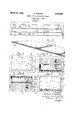
- Fig. 1 is a plan view of a portion of the laid covering
- Fig.2 is an enlarged sectional view, with parts in perspective, taken on line 21-2 of Fig. I;
- Fig. 3 is a plan view of one of the individual sections of roofing material applied to its underlying support prior to being laid by the method of my invention
- Fig. 4 is a view illustrating the first step of my improved method
- Fig. 5 illustrates the second step of the method
- Fig. 6 shows the section of roofing material applied to its underlying support following the step referred to.
- the prepared roofing material is supplied in relatively long lengths by the manufacturer and usually in rolled form.
- I cut the long strips into sections, which I have indicated at'l, 1 in the drawing. These sections as previously stated, are approximately feet long by 32 to 36 inches in width, which is the width of the stripsas manufactured. This reduces the material to more readily handable form, and the sections so provided are individually treated and 'laid in the following manner.
- the section is first laid at its proper position on the underlying support, as indicated in Fig. 3 In this figure. I have indicated a longitudinal center line 3 which divides the section into lohgitudinal half portions 4, 5.
- the half portion 4 contains the front'longitudinal edge of the section, this edge being serrated as shown.
- the section after being laid on the support is folded or bent back on itself along its longitudinal center line 3 to position the half portion 4 over the half portion 5, as shown in Fig. 4.
- the underlying support 2 in that portion to becovered by the half portion 4 is coated with this hot fiowable material, as indicated at 7 in Fig. 4.
- These coatings may be applied in any desired manner, as by the use'of the usual roofing mops 8.
- the coatings are applied practically simultaneously, one workman coating the folded over portion of thesection and another coating the portion of the support to be covered by the coated section. This is done in order that there shall be no appreciable lapse of time between the application of the coatings and thus both coatings are still hot when the coated portion 4 is swung or dropped down on the coated support 7-.
- the hot material penetrates the roofing sheet and breaks down the binder of the sheet so that the sheet becomes sufliciently pliable and limp that it may be readily and easily pressed against the coated support throughout its entire area, thereby obtaining a secure and effective bond between the section and the support.
- the uncoated portion 5 of the section is folded or bent back along the line -3 over the anchored portion 4 as indicated in Fig. 5.
- the exposed underside of the portion 5 is then coated with the hot bituminous material as at 9 by a mop 8 as shown, and at the same time the portion of the support 2 to be covered by the portion 5 is coated with the same material as indicated at 10 in Fig. 5.
- These coatings are applied in the same manner'as described for the portion 4, and the portion 5 is rendered flexible and limp so that it may be dropped or swung-down on its coated support and pressed against the same to complete the bonding of the section to the support.
- the coated portions of the section are pressed throughout their entire areas firmly against the coatings on the support to exclude all free air from between the section and the support and to intimately connect the section throughout to the support.
- coatings 7 and 10 on the support are extended beyond the margins of the section to insure a complete bonding of the section throughout, including its margins, with the support.
- the coatings are applied to the support to extend under the section where folded along its longitudinal center line while preparing the half portions of the section for laying.
- the sections may be made to conform to 3.
- the und r supp rt may b w od, concrete, sisting in substantially simultaneously applying 25 brick, tile or a composite material of a character separate coatings of hot, flouße bonding maempl y d f r r fin pu p ses.
- Wh l in a terial to the entire areas ofsubstantially co-ex- I have shown t e f c e in as comprising tensive portions of the sheet aniline supporting on y ne l y t it i within the Scope of my surface, respectively, prior to laying the coated invention to embody it in as many layers as may be desired. In such case, one layer would cover supporting surface, then laying the coated sheet the other, each layer, however, being laid of indion the coated supporting surface with their coatvidual sections as herein described.
- the coatings being applied to successive half sections of the sheet 'derlying supporting surface, consisting in separately applying two coatings of hot flowable bituminous material, one to the portion of the supporting surface to be covered by the sheet the coatings are'still hot pressing the soft, pliable coated sheet against the coated supporting surface to'cause the coated sheet to. followjhe and to the crrespnding P of the Suppl); contour of the coated support to effectively bond to be covered thereby to avoid setting of the t t t t support.
Landscapes
- Engineering & Computer Science (AREA)
- Architecture (AREA)
- Civil Engineering (AREA)
- Structural Engineering (AREA)
- Roof Covering Using Slabs Or Stiff Sheets (AREA)
Description
A. ,WIND ING mm'flbn 'oF LAYING ROOFING SHEETS Filed June 5 19 33 Fig.1.,
AAAAAAAAA ATTORNEY? 'Patented Mar.12 ,1935 I 1 9 4 2 2 UNITED STATES PATENT OFFICE METHOD or LaYn'vo noormo SHEETS Arthur Winding, Milwaukee, Wis.
Application June 5, 1933, Serial No. 674,356
' 6 Claims. (01. 108-7) This invention relates to a novel method of bulged portions being unable to support any aplaying prepared composite sheet roofing and to preciable weight. the roofing when laid. The general purpose and object of my inven- Prepared roofing of the character referred to, tion isto provide a method by which roofing mais furnished by themanufacturer in relatively terial of the characterreferred to may be so 5 long, sheet-like strips, in rolled form. The neclaid that the foregoing objections are entirely essary ingredients of the material are secured overcome by reason of the type of the bond pro-- together in a homogeneous mass by a bituminous vided between the support and the roofing mabinder which is incorporated'in the material at terial.
10 the time of its manufacture. This binder .is of In carrying out the objects of my invention, I 10 course set when the material is placed on the coat the underside 'of the roofing sheet preparamarket and gives the-material the rigidity and tory to its application to thesupport with a hot hardness required for a roof covering. While fiowable bituminous material, such as pitch or this binder renders the material relatively stiff asphalt, and at substantially the same time apply and rigid, the material is not so inflexible that a coating of said hot flowable bituminous mate- 15 it cannot be supplied in-rolled form or be readily rial t the portion o t upp t b covered and easily unrolled for roof applying purposes. by the sheet. The hot asphalt enters the sheet In laying the material, the practice heretofore and breaks down the binder therein, rendering has been to mop or coat' the underlying support the sheet soft and pliable, whereby the sheet with a hot fiowable pitch or asphalt to the width may b p pe ly pressed against h coated p- 20 and length of the roofing strip to be laid" and port to conform to the contour thereof. The then unroll the strip on the coated support. sheet is pressed against the support while the This method of laying produces an imperfect and bitumino coatings are still hot, thus obtaining inefi'ective bond between the strip and the supa perfect b nd between the sheet and the support.
" port because portions of the coating not infre- This is possible because the soft, pliable sheet 5 quently cool off and set before reached by the can be pressed throughout its entire area against strip and because the strip by reason of the set the coated support to exclude all free air from binder therein is far too inflexible to be properly between the sheet and the support and to adhere pressed against the coated support and conform the sheet throughout to the support regardless to the contour thereof. -This contour in most of the irregularity of the latter. Thus, the roof 30 .cases is quite irregular and replete with high covering when laid cannot buckle, warp or blister, points and depressions over its entire surface. because of the effectiveness of the bond between Thus a roof covering secured in this way will the sheet and the support and of the absence of readily buckle and warp due to the expanding of entrapped air between them. Also, the covering 5 the air which is trapped between the covering in fitting the contour of the support will present and the support at the places of insecure cona smooth and even outer surface. By reason of nection between them. A- roof covering so laid the bonded connection of the sheet throughout will also open up at the joints between the strips its entire area, a leak through the sheet due to a providing an entrance for water and moisture to defect therein will be confined within the defective '40 P d leaks- With mafiy 10058 Bind ecu e region and will not spread over the sheet or to 40 an outlet in the underlying support. In practice,
, connections between the strips and thesupport, adja ent h t as t Water entermg at an open lap thmugh To avoid undue cooling of the coatings between fective or damaged strip, may travel a considertheir application to the sheet and the support, I
able distance under the covering before reaching and the pressing of the coated sheet against the coated support, I cut the roofing material as ob- 45 this may be'many feet from the place Oren tained from the manufacturer in sections of a zz rgg'gg zgg i z fl i g g fifig ggf size capable of being readily and easily handled Wa ing and buckling of the roof covering not by P laying the roof- These sectims only Psubjects it to undue strain, pulling it away are ufdivlduany'coated as they P' laid- P -l from its support, but produces an unsightly roof, enab1 1n8 the y g to be ca ied on While the bj ted to by ow er engineers d architects, bonding material is still hot, even in the coldest due to its uneven and irregular outer surface. Seasons of the y In al Pr he e- Moreover, a covering of this character is likely tions are cut to sizes ranging usually 10 feet long 56 to be damaged, when walked upon, due to the by32 to 36 inches in width,the latter dimension being the usual width of the strips as manufactured.
In laying the sections, they are usually folded or doubled longitudinally on themselves, so that the hot bituminous material may be applied to one half of a section at a time. This lessens the chance of the coating material setting as the sec tions are laid, due to the rapidity permitted in pressing half of the sections against the coated portion of the support, as compared to the entire area of the section. Only the portion of the support to be covered by half a section is coated at a time, thus keeping the bonding material hot for the proper securing of the section to the support. Applying the bonding material to both the section and the support, produces a double thickness of such material, thus insuring a more effective bond and requiring a longer time to cool which is an important factor in laying the sections.
The accompanying drawing illustrates a roof covering laid in accordance with my invention and also the method of treating and laying the individual sections.
Fig. 1 is a plan view of a portion of the laid covering; I I
Fig.2 is an enlarged sectional view, with parts in perspective, taken on line 21-2 of Fig. I;
Fig. 3 is a plan view of one of the individual sections of roofing material applied to its underlying support prior to being laid by the method of my invention;
Fig. 4 is a view illustrating the first step of my improved method;
Fig. 5 illustrates the second step of the method; and
Fig. 6 shows the section of roofing material applied to its underlying support following the step referred to.
In the drawing,'1, 1 indicates sections of the prepared roofing material heretofore referred to, and 2 indicates the underlying support to which the sections are applied as a covering therefor. The sections 1 are applied to the support 2 in overlapping relation, there being the desired amount of marginal overlap between them. The exposed longitudinal edges of the sections may be straight or they may be serrated, as shown, to increase the effectiveness of the bond of the sec tions at such edges-with the support as set forth in and covered by my Patent No. 1,550,299, granted August 18, 1925.
As heretofore pointed out, the prepared roofing material is supplied in relatively long lengths by the manufacturer and usually in rolled form. In laying this material in accordance with my invention, I cut the long strips into sections, which I have indicated at'l, 1 in the drawing. These sections as previously stated, are approximately feet long by 32 to 36 inches in width, which is the width of the stripsas manufactured. This reduces the material to more readily handable form, and the sections so provided are individually treated and 'laid in the following manner.
The section is first laid at its proper position on the underlying support, as indicated in Fig. 3 In this figure. I have indicated a longitudinal center line 3 which divides the section into lohgitudinal half portions 4, 5. The half portion 4 contains the front'longitudinal edge of the section, this edge being serrated as shown.
The section after being laid on the support, is folded or bent back on itself along its longitudinal center line 3 to position the half portion 4 over the half portion 5, as shown in Fig. 4. This exposes or brings uppermost the underside of the half portion 4, whereupon the workman coats the exposed underside of the section with a coating of hot flowable bituminous material, such as pitch or asphalt, as indicated at 6 in 'Fig. 4. At the same time, the underlying support 2 in that portion to becovered by the half portion 4, is coated with this hot fiowable material, as indicated at 7 in Fig. 4. These coatings may be applied in any desired manner, as by the use'of the usual roofing mops 8. In practice, the coatings are applied practically simultaneously, one workman coating the folded over portion of thesection and another coating the portion of the support to be covered by the coated section. This is done in order that there shall be no appreciable lapse of time between the application of the coatings and thus both coatings are still hot when the coated portion 4 is swung or dropped down on the coated support 7-. In applying the hot coating to the folded over portion of the section, the hot material penetrates the roofing sheet and breaks down the binder of the sheet so that the sheet becomes sufliciently pliable and limp that it may be readily and easily pressed against the coated support throughout its entire area, thereby obtaining a secure and effective bond between the section and the support.
After the .coated portion 4 of the section-has been secured to the support, the uncoated portion 5 of the section is folded or bent back along the line -3 over the anchored portion 4 as indicated in Fig. 5. The exposed underside of the portion 5 is then coated with the hot bituminous material as at 9 by a mop 8 as shown, and at the same time the portion of the support 2 to be covered by the portion 5 is coated with the same material as indicated at 10 in Fig. 5. These coatings are applied in the same manner'as described for the portion 4, and the portion 5 is rendered flexible and limp so that it may be dropped or swung-down on its coated support and pressed against the same to complete the bonding of the section to the support. The coated portions of the section are pressed throughout their entire areas firmly against the coatings on the support to exclude all free air from between the section and the support and to intimately connect the section throughout to the support.
- The section so bonded is indicated in Fig. 6. The
coatings 7 and 10 on the support are extended beyond the margins of the section to insure a complete bonding of the section throughout, including its margins, with the support. The coatings are applied to the support to extend under the section where folded along its longitudinal center line while preparing the half portions of the section for laying.
In treating and applying each individual sec tion to the underlying support in the manner shown and described, the several sections are secured throughout to the underlying support, thereby producing a non-buckling, nonblistering and non-warping roof covering. Moreover, as before stated, a bonding union of this character prevents open laps when the sections overlap and also localizes any leaks which may occur in the sections due to defective or damaged material. In referring to the underlying support, I have reference to not only the support 2, but the overlapped portions of the adjacent sections as shown in Figs. 1 and 2. These portions of the previously laidsections are coated with the hot bonding material when y n the following sections.
In applying the hot flowab e bituminous inahot fiowable bituminous material, one to the unterial to the sections and also to the underlying derside of the folded section of the sheet, am!
support, I not only secure an effective bond but the other to the portion of the support to be covalso double the amount of bonding material emered thereby, and finally pressing the last coated ployed, thereby retaining the heat longer which .section against the last coated portion of the supg a is essential when laying the roof covering incool port, while the bituminous coatings on the sheet or cold weather. In rendering the sections'limp and the support are still hot to secure the entire by the application of the hot bonding material sheet to the support.
thereto, the sections may be made to conform to 3. The method of laying a. prepared roofing the irregular contour of the support on pressing sheet on an underlying supporting surface, conthe sections against ,the same. This is facillsisting in separately applying two coatings of tated by having the sections of a size that they hot flowable bondingmateriahone to the under may be pressed over their entire surface by the side of. the sheet, and the other to the portion workmen laying them while the coatings arestill ofthe supporting surface to be covered by the hot. This insures an effective bond because it coated sheet, laying the coated sheet on the includes the high, the low and all intermediate coated supporting surface with their coatings in points of the receiving surfacepf the support, contact, and while the coatings are still hot press-" a d p s a -warp n and non-buc l n ing the coated sheet throughout its entire coated roof covering due not only to the intimate cona against the coated supporting surface to Electi n thr w n th oati u to cause the coated sheet to follow the contour of 20.
the exclusion of free air between the covering the at d su ort to efi'ectively bond the sheet and the support. In practice, the bonding mat t t, 1
terial'is used when at a temperature between 450 4, The method. of laying a prepared roofing and 0 degrees h h i sheet on an underlying supporting surface, con- The und r supp rt may b w od, concrete, sisting in substantially simultaneously applying 25 brick, tile or a composite material of a character separate coatings of hot, flowahle bonding maempl y d f r r fin pu p ses. Wh l in a terial to the entire areas ofsubstantially co-ex- I have shown t e f c e in as comprising tensive portions of the sheet aniline supporting on y ne l y t it i within the Scope of my surface, respectively, prior to laying the coated invention to embody it in as many layers as may be desired. In such case, one layer would cover supporting surface, then laying the coated sheet the other, each layer, however, being laid of indion the coated supporting surface with their coatvidual sections as herein described. After a m in t t, and while the coatings are still C E has been laid it y d usually hot pressing the coated sheet throughout its encoated with the same bonding material asused for s c th sections to e pport. surface to cause the coated sheet to follow the The details of construction and arrangement b t of ,t coated support, toeflectively'bond of parts shown and described may be variously t et; t t t, changed and modified without departing from Themethod of laying prepared roofing the spirit and scope of my invention, except aspointed out in the appended claims.
I claim as my invention; f
l. The method of laying a prepared roofing sheet on a support, consisting in separately applying two coatings of hot flowable bituminous material, one to the underside of th Sheet. and prepare the sheet for application to the supthe other to the portion ofthe support to be covporting surface and t br ak down the binder ered by the sheet, and then pressing the coated in the sheet 1 render t Sheers soft nd pliable,
sheet against the coated support while the bitulaying the, coated Sheet on t coated supporting minous coatings on the sheet and the support are still hot to securean effective bond between the sheet and the support, the coatings being applied to successive half sections of the sheet 'derlying supporting surface, consisting in separately applying two coatings of hot flowable bituminous material, one to the portion of the supporting surface to be covered by the sheet the coatings are'still hot pressing the soft, pliable coated sheet against the coated supporting surface to'cause the coated sheet to. followjhe and to the crrespnding P of the Suppl); contour of the coated support to effectively bond to be covered thereby to avoid setting of the t t t t support. i coating material in the application of;the sheet T method r laying, a readily dl bl I tothe support. v section of prepared sheet roofing on anunder- The method 1' 8 8 a prepared roofing lying supporting surface, consisting" in substansheet on a support, consisting in laying the sheet tiauy simultaneously applying separate coatings on the support, folding the sheet back on itself gh flowablgbondmg to expose thesunderside of the folded section of the sheet, separately applying two coatings of hot flowable bituminous material, one to the underside of the folded sectioned the sheet and the other to the portion of the support to be cov-' ered thereby, then pressing the coated section of the sheet against the coated support whilethe bituminous coatings on the sheet and the support are still h'ot to secure the-coated'section of the sheet to the coated support, then folding the remaining uncoated section of the sheet back on contour of the coated support a; the portion of the sheetsecured to the support, the sheet to the support I and a ain separately. applyin two coe s of AR'IHUR wmnmcf tions of the supporting surface, respectively; lay ing 'the coated portions of the sheet on the coated portions of supporting surface to-contact the- ,the coatings to the sheet and the support, and while the coatings on said portions are still hot pressing the coated sheet throughout its entire coated area against the coated .slillilwrtingv sur-' effectively bond portion of the sheet on the coated portion of the 30 tire coated area against the coated supporting 35 sheet containing a bituminous binder on an un- 4 and the other to the under side or the sheet to 45 surface with their coatings in contact and while 50 material to successive portions of the sheet and to corresponding porcoatings immediately following the application of 5 face to cause the coated sheetto follow the
Priority Applications (1)
| Application Number | Priority Date | Filing Date | Title |
|---|---|---|---|
| US674356A US1994262A (en) | 1933-06-05 | 1933-06-05 | Method of laying roofing sheets |
Applications Claiming Priority (1)
| Application Number | Priority Date | Filing Date | Title |
|---|---|---|---|
| US674356A US1994262A (en) | 1933-06-05 | 1933-06-05 | Method of laying roofing sheets |
Publications (1)
| Publication Number | Publication Date |
|---|---|
| US1994262A true US1994262A (en) | 1935-03-12 |
Family
ID=24706270
Family Applications (1)
| Application Number | Title | Priority Date | Filing Date |
|---|---|---|---|
| US674356A Expired - Lifetime US1994262A (en) | 1933-06-05 | 1933-06-05 | Method of laying roofing sheets |
Country Status (1)
| Country | Link |
|---|---|
| US (1) | US1994262A (en) |
Cited By (6)
| Publication number | Priority date | Publication date | Assignee | Title |
|---|---|---|---|---|
| US3291195A (en) * | 1961-08-25 | 1966-12-13 | Walnut Ind Company | Tape reinforced grain door panel |
| US3307989A (en) * | 1964-06-15 | 1967-03-07 | Norman P Harshberger | Roofing product and method of application |
| US3344915A (en) * | 1965-07-22 | 1967-10-03 | Parke Davis & Co | Package |
| US3522119A (en) * | 1967-04-10 | 1970-07-28 | Gennosuke Mori | Method of applying a waterproofing sheet to a structural surface |
| US3619314A (en) * | 1968-01-05 | 1971-11-09 | Strati France Sa | Method of joining adjacent sheets of elastomeric material on a support structure |
| US3922425A (en) * | 1970-09-14 | 1975-11-25 | Owens Corning Fiberglass Corp | Roofing board for integration in a built-up roofing structure |
-
1933
- 1933-06-05 US US674356A patent/US1994262A/en not_active Expired - Lifetime
Cited By (6)
| Publication number | Priority date | Publication date | Assignee | Title |
|---|---|---|---|---|
| US3291195A (en) * | 1961-08-25 | 1966-12-13 | Walnut Ind Company | Tape reinforced grain door panel |
| US3307989A (en) * | 1964-06-15 | 1967-03-07 | Norman P Harshberger | Roofing product and method of application |
| US3344915A (en) * | 1965-07-22 | 1967-10-03 | Parke Davis & Co | Package |
| US3522119A (en) * | 1967-04-10 | 1970-07-28 | Gennosuke Mori | Method of applying a waterproofing sheet to a structural surface |
| US3619314A (en) * | 1968-01-05 | 1971-11-09 | Strati France Sa | Method of joining adjacent sheets of elastomeric material on a support structure |
| US3922425A (en) * | 1970-09-14 | 1975-11-25 | Owens Corning Fiberglass Corp | Roofing board for integration in a built-up roofing structure |
Similar Documents
| Publication | Publication Date | Title |
|---|---|---|
| US1843370A (en) | Irregular strip shingle | |
| US2099131A (en) | Thick butt shingle | |
| US2219450A (en) | Strip shingle | |
| US4091135A (en) | Laminated bituminous roofing membrane | |
| US2210209A (en) | Composition shingle | |
| US1765796A (en) | Sealed laminated roofing element | |
| US4565724A (en) | Roofing-material | |
| US1994262A (en) | Method of laying roofing sheets | |
| US2705209A (en) | Roofing | |
| US3042193A (en) | Self-sealing shingle | |
| US2139816A (en) | Highway | |
| US1447290A (en) | Shingle or block construction | |
| US1939004A (en) | Air, moisture, and sound proof material | |
| US2277892A (en) | Flooring construction | |
| US2036123A (en) | Dampproof structure and method of constructing same | |
| US1578663A (en) | Waterproofing construction | |
| US2153887A (en) | Flexible cement roofing | |
| US1975986A (en) | Covering for surfaces exposed to the weather | |
| US2125694A (en) | Double layer cardboard roof | |
| US1551318A (en) | Method of manufacturing composite boofing | |
| US2356570A (en) | Covering element | |
| US1908127A (en) | Metal sheathed roof | |
| US2032083A (en) | Building material | |
| US1779175A (en) | Roofing and process of making the same | |
| US1340348A (en) | Roof-shingle |