US1985366A - Button sewing machine - Google Patents
Button sewing machine Download PDFInfo
- Publication number
- US1985366A US1985366A US392308A US39230829A US1985366A US 1985366 A US1985366 A US 1985366A US 392308 A US392308 A US 392308A US 39230829 A US39230829 A US 39230829A US 1985366 A US1985366 A US 1985366A
- Authority
- US
- United States
- Prior art keywords
- needles
- looper
- loop
- loops
- button
- Prior art date
- Legal status (The legal status is an assumption and is not a legal conclusion. Google has not performed a legal analysis and makes no representation as to the accuracy of the status listed.)
- Expired - Lifetime
Links
Images


Classifications
-
- D—TEXTILES; PAPER
- D05—SEWING; EMBROIDERING; TUFTING
- D05B—SEWING
- D05B3/00—Sewing apparatus or machines with mechanism for lateral movement of the needle or the work or both for making ornamental pattern seams, for sewing buttonholes, for reinforcing openings or for fastening articles, e.g. buttons, by sewing
- D05B3/12—Sewing apparatus or machines with mechanism for lateral movement of the needle or the work or both for making ornamental pattern seams, for sewing buttonholes, for reinforcing openings or for fastening articles, e.g. buttons, by sewing for fastening articles by sewing
- D05B3/14—Sewing apparatus or machines with mechanism for lateral movement of the needle or the work or both for making ornamental pattern seams, for sewing buttonholes, for reinforcing openings or for fastening articles, e.g. buttons, by sewing for fastening articles by sewing perforated or press buttons
-
- D—TEXTILES; PAPER
- D05—SEWING; EMBROIDERING; TUFTING
- D05B—SEWING
- D05B65/00—Devices for severing the needle or lower thread
Definitions
- This invention relates to machines for sewing on buttons and particularly to machines for sewing on four-hole fiat buttons.
- the invention has for an object to provide a. machine for sewing on fourhole buttons with two separately appearing parallel groups of tacking stitches and without an objectionable diagonal connecting thread between such groups of stitches on the exposed face of the button".
- Another object of the invention is to provide a machine having increased ca: pacity for production, that is, one which will turn out more work in a given time than machines heretofore made for sewing on four-hole buttons.
- a further object of the invention is to provide an improved button-attaching seam which is strong and reliable, and which may be expeditiously sewed by a machine.
- a sewing machine having two needles and a buttonclamp preferably vibrating transversely of the plane of the needles.
- the needles are spaced apart a distance preferably equal to one side of the square defined by the holes in the button and the amplitude of vibration of the button-clamp is preferably made equal to the adjacent sides of such square, so'that the needles will simultaneously sew two groups of separately appearing tacking stitches through the holes and within the periphery of the button.
- the needles preferably cooperate with a suitable loop-taker below the work which successively keys the needle-thread loops in pairs, such loop-taker being preferably in the form of a rotary chain-stitch looper having the usual loop-seizing beak and loop-spreading wing operating to give the needle-loops a half-twist and hold them spread while the beak seizes a pair of new needle-loops and carries them through the previously formed and spread pair of loops.
- the machine is also preferably fitted with suitable loop-handling devices to insure that the previously formed needle-loops will be spread and both held to one side of the needles so that the looper-beak will seize the new pair of needleloops before entering the previously formed loops.
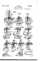
- Fig. 1 is a side elevation, partly in section, of a button-sewing machineembodying the invention.
- Fig. 2 is a bottom plan view of the machine bed.
- Fig. 3 is a top plan view of the looper and loop-spreading devices.
- Fig. 4 is a section on the line 4-4, Fig. 2.
- Fig. 5 1s a section on the line 5--5, Fig. 1.
- Fig. 6 is a front end elevation of the stitch-forming devices and button-clamp.
- Fig. '7 is a similar view showing the loop-positioner in operation.
- Fig. 8 is a similar view at a laterv stage in the stitch-forming cycle showing the loop-spreader in operation.
- Fig. 9 is a side elevation of the stitch-forming mechanism and associated parts in the same relative positions shown in Fig. 8.
- Fig. 10 is a reverse side elevation ofthe parts shown in Fig. 9.
- Fig. 11 is a view similar to Fig. 10 but with the parts in the respective positions shown in Fig. 7.
- Figs. 12 to 16, inclusive, are perspective views illustrating a complete stitchforming pycle of operations.
- Fig. 17 is a section on the line 1'l17, Fig. 7.
- Fig. 19 is a perspective view of the attached button.
- the invention is disclosed as embodied in a button sewing machine of the well known Singer 114 class, represented in the Fifield Patents'No. 1,316,022, of Sept. 16, 1919, and No. 1,525,643, of Feb. 10, 1925.
- a machine of this class has a bed 1, standard 2 and overhanging bracket-arm 3 terminating in the head 4 in which is mounted the reciprocating needle-bar 5 carrying, in the present instance, two-needles 6 which are spaced apart transversely of the bed 1 a distance equal to one side a, Fig. 18, of the square defined by the holes of a four-hole button b held in the usual button-clamp 7 designed to be reciprocated longitudinally of the bed 1 in the usual manner by the longitudinal feed-cam 8 in the pattern wheel 9.
- the present machine has no lateral feed mechanism for the button-clamp; the latter being moved only longitudinally of the bed 1.
- the amplitude of the reciprocating movement of the work-clamp is equal to the length of the sides 0 adjacent the side a of the square defined by the holes in the button b.
- the main-shaft 10 of the machine is journaled in the bracket-arm 3 and is connected at its forward end, as usual, to the needle-bar 5. It also drives the pattern wheel 9 through the usual worm-and-gear connection 11. It also drives the lower horizontal shaft 12 through the intermediate vertical shaft 13 having the bevel-gear connections 14, 15 at its opposite ends with the shafts 10 and 12, respectively.
- the period of action of the main-shaft 10 is controlled by the usual stop-motion device 16.
- the rotary chain-stitch looper 18 carried by the looper-shaft 19 which is journaled in the bed 1 with its center line somewhat above the center line of the looper-driving shaft 12.
- the shaft 12 has fixed to it a crank-disk carrying a crank-pin 21 which is connected by the link 22 to the crank-pin 23 on the crank-disk 24 flzed to the looper-shaft 19.
- the oflsetting of the centers of the shafts 19 and 12 from one another causes the shaft 19 to be driven with a variable or fast-and-slow motion; the radial dotted lines on the crank disk 24, Fig. 5, indicating the movements of the looper-beak for equal 30 movements of the driving crank-disk 20. From this figure it will be observed that the looper-beak is driven rapidly while executing the upper or loop-seizing part of its motion and more slowly while executing. the lower part of its motion.
- the circular path of the looper-beak is parallel to the plane of the needles and the looper operates to seize thread-loops from the needles and pass them substantially simultaneously through the previously seized and spread needle-loops which are subsequently cast off from the looper and drawn up to the work; the previously formed pair of needle-loops embracing and being keyed by the new pair of needle-loops.
- Means are provided in the present machine for collectively positioning both previously formed needle-loops on the looper at the rear of both needle-paths, so that the needles will descend in front of such loops and in position to have their new loops seized by the looper-beak and passed collectively through the previously formed loops.
- the means to this end consists of a loop-positioner 25 having a hooked extremity affording a loop-engaging edge 26, Fig. 3, and a needle-receiving notch or recess 27 in front of such edge.
- the shank of the loop-positioner 25 is mounted on the head 28 of the rock-shaft 29 journaledin the cylindrical boss 30 at the free end of the bracket 31 which is screwed to one tine of the forked forwardly disposed arm 32 of a U-shaped rocking frame 33 journaled freely on the shaft 34 which is mounted below and parallel to the looper-shaft in the bearing rib 35 and bearing block 36 below the bed 1.
- the U-shaped rocking frame 33 embraces the bearing rib 35, as shown in Figs. 1 and 2, and its upwardly extending and forked arm 32 embraces an eccentric 3'7 on the looper-shaft 19 which imparts to the loop-positioner 25 its components of motion parallel to the plane of the needles 6.
- the rock-shaft 29 which carries the looppositioner 25 has fixed to its lower end a crankarm 38 carrying a ball 39 which is connected by the link 40 to tho bail-stud 41 on the lever 42 fulcrumed on the screw 43 below the bed 1 and having at its free end a cam-follower 44 entering the groove 45 of a barrel-cam 46 fixed to the looper-shaft 19.
- the cam 46 imparts to the 'loop-positioner 25 the components of its motion transversely of the plane of the needles 6.
- the two motions of the loop-positioner 25 are so compounded as to move the point 47 of the latter, Fig. 3, in a substantially rectangular orbital path 48, so that the edge 26 of the loop-positioner will move to the right along the lower side of its path, Fig.
- a loopspreader 50 in the form of a curved finger having its extremity forked at 51 to embrace the needles 6.
- the loop-spreader 50 is mounted on the rock-shaft 34 and has a limited rocking movement relative to such shaft.
- Fixed to the rock-shaft 34 is the needle-guide 52 which engages the needles and holds them against deflection into the path of the looper-beak.
- Fixed to the shank of the needle-guide 52 is a pin 53 which enters an arcuate slot 54 in the shank of the loop-spreader 50.
- the rock-shaft 34 has fixed to it an arm 58, Figs. 2 and 4, carrying a roller 59 which engages a cam 60 on the looper-shaft 19.
- a spring 61 anchored at one end to the bearing boss 36 and at its opposite end to a collar 62 on the shaft 34 retains the follower 59 in engagement with the cam 60.
- the cam 60 has a long concentric portion 60' which holds the needle-guide 52 and loop-spreader 50 in their retracted or ineffective positions, Fig. 6. As the beak of the looper 18 is approaching the needles, between the position shown in Fig. 12 and that shown in Fig.
- the let-off portion 60 reaches the roller 59 and permits the spring 61 to quickly project the loop spreader 50 and needle-guide 52 to their operative positions shown in Figs. 8, 9, 10 and 13. It will be observed in Figs. 9 and 10 that the loopspreader 50 bends one limb of each of the needleloops outwardly and well beyond the path of the looper-beak, so that the looper-beak will pass safely between the limbs of the spread needleloops without danger of catching such loops.
- the accelerated and retarded movement of the looper effected by the variable motion driving connections 21, 22, 23, causes the looper-beak to be quickly projected across the space between the two needles so that both needle-loops will be seized at the proper time in the rising movement of the needles.
- the machine is preferably provided with thread-cutting mechanism constructed substantially in accordance with the disclosure of the Fifleld Patent No. 1,251,451, of Dec. 25, 1917.
- Such thread-cutting mechanism comprises a thread-cutting lever 62' fulcrumed at 63 on the underside of the throat-plate 1'7 and actuated by the usual connections with the stop-motion device as explained in said Fifield Patent No. 1,251,451.
- the button b is shown attached to the body-fabric f by two fastening threads d, e, of which the thread 01 extends back and forth on the exposed face of the button and is formed into loops m, m m passing through two of the holes in the button.
- the second fastening thread e also extends back and forth on the exposed face of the button and is formed into loops n, n 11 passing through the remaining 2 sma G MA'T'l'llNisn,
- the loops m, n constitute the first pair of loops and this pair of loops is entered and keyed by the second pair of loops m, n, which, in turn, is entered and keyed by the third pair of loops m 12 etc., the finishing ends t, t of the threads being preferably drawn through the last pair of loops to key such loops. It will be observed in Fig. 19 that the groups of threads d, e on the upper or exposed face of the button are separated and lie in spaced parallel relation with no cross or diagonal connecting thread or threads.
- a rotary chain-stitch looper having a loop-seizing beak and a loop-spreading wing, said beak being arranged to operate in a plane parallel to the plane of the needles and being adapted to seize a thread-loop from each of said needles and pass it through the previously seized thread-loops on the looper.
- a rotary chain-stitch looper having a beak operating in a plane parallel to the plane of the needles, and means for collectively positioning the needle-loops in rear of the needle-paths, so that the looper will seize new needle loops and pass them collectively through the previously seized needle loops.
- a sewing machine in combination, a plurality of needles arranged in a plane, a rotary chain-stitch looper having a beak operating in a plane parallel to the plane of the needles, and means for moving the work transversely of the plane of the needles.
- a sewing machine in combination, a plurality of eye-pointed needles operating in a plane, a rotary chain-stitch looper cooperating with said needles, a main-shaft connected to reciprocate said needles, and a variable motion driving connection between said main-shaft and said I.
- a sewing machine in combination, a plurality of eye-pointed needles operating in a plane, a rotary chain-stitch looper having a beak operating in a plane parallel to the plane of the needles, a looper-shaft carrying said looper, a main-shaft connected to reciprocate said needles, a looper-driving shaft in end-to-end relation with the looper-shaft, the axes of the last two mentioned shafts being offset from one another, a crank on each of said shafts, and a link-connection between said cranks.
- a reciprocating needle in combination, a reciprocating needle, a rotary chain-stitch looper, a rock-shaft, and needle-guide and loop-spreading implements actuated differentially by said rock-shaft.
- a reciprocating needle in combination, a reciprocating needle, a rotary chain-stitch looper, means for engaging a needle-loop on the looper and positioning it in rear of the needle-path, and means independent of said looper and loop-positioner for entering the needle-loop while engaged by the loop-positioner and spreading such loop.
- stitch-forming mechanism including a plurality of eye-pointed needles arranged in a plane and a rotary chain-stitch looper having a beak operating in a plane parallel to the plane of said needles and cooperating with said needles to form stitches, of a button-clamp, and means for rela-.' tively moving the stitch-forming mechanism and button-clamp transversely of the plane of the needles.
- a button-sewing machine the combina-l tion with a plurality of needles arranged in a plane, of a rotary chain-stitch looper cooperating with said needles to form stitches, a loopercarrying shaft disposed transversely of the plane of the needles, a button-clamp and means for moving the button clamp to-and-fro transversely of the plane of the needles.
Landscapes
- Engineering & Computer Science (AREA)
- Textile Engineering (AREA)
- Sewing Machines And Sewing (AREA)
Description
Dec. 25, 1934. A. F. FIFIELD BUTTON SEWJ ING MACHINE Filed Sept. 13) 1929 I5 Sheets-Sheet 1 tax gme'ntoz flaw/m,
WMM
A. F. FIFIELD BUTTON SEWI NG MACHI NE .Dec. 25, 1934.
Filed Sept. 13, 1929 (5 Sheets-Sheet 2 gmvnto'r,
" Dec. 25, 1934. I A F, E D 1385 366 BUTTON SEWING MACHINE Filed Sept. 13, 1929 3 Sheets-Sheet 3 Y Albera FfiZ/Zeld duomq Patented Dec. 25, 1934 UNITED STATES PATENT OFFICE BUTTON SEWING MACHINE Application September 13, 1929, Serial No. 392,308
9 Claims.
This invention relates to machines for sewing on buttons and particularly to machines for sewing on four-hole fiat buttons. The invention has for an object to provide a. machine for sewing on fourhole buttons with two separately appearing parallel groups of tacking stitches and without an objectionable diagonal connecting thread between such groups of stitches on the exposed face of the button". Another object of the invention is to provide a machine having increased ca: pacity for production, that is, one which will turn out more work in a given time than machines heretofore made for sewing on four-hole buttons. A further object of the invention is to provide an improved button-attaching seam which is strong and reliable, and which may be expeditiously sewed by a machine.
With the above and other objects in view, as will hereinafter appear, there is provided a sewing machine having two needles and a buttonclamp preferably vibrating transversely of the plane of the needles. The needles are spaced apart a distance preferably equal to one side of the square defined by the holes in the button and the amplitude of vibration of the button-clamp is preferably made equal to the adjacent sides of such square, so'that the needles will simultaneously sew two groups of separately appearing tacking stitches through the holes and within the periphery of the button. The needles preferably cooperate with a suitable loop-taker below the work which successively keys the needle-thread loops in pairs, such loop-taker being preferably in the form of a rotary chain-stitch looper having the usual loop-seizing beak and loop-spreading wing operating to give the needle-loops a half-twist and hold them spread while the beak seizes a pair of new needle-loops and carries them through the previously formed and spread pair of loops. The machine is also preferably fitted with suitable loop-handling devices to insure that the previously formed needle-loops will be spread and both held to one side of the needles so that the looper-beak will seize the new pair of needleloops before entering the previously formed loops.
In the accompanying drawings Fig. 1 is a side elevation, partly in section, of a button-sewing machineembodying the invention. Fig. 2 is a bottom plan view of the machine bed. Fig. 3 is a top plan view of the looper and loop-spreading devices. Fig. 4 is a section on the line 4-4, Fig. 2. Fig. 5 1s a section on the line 5--5, Fig. 1. Fig. 6 is a front end elevation of the stitch-forming devices and button-clamp. Fig. '7 is a similar view showing the loop-positioner in operation.
Fig. 8 is a similar view at a laterv stage in the stitch-forming cycle showing the loop-spreader in operation. Fig. 9 is a side elevation of the stitch-forming mechanism and associated parts in the same relative positions shown in Fig. 8. Fig. 10 is a reverse side elevation ofthe parts shown in Fig. 9. Fig. 11 is a view similar to Fig. 10 but with the parts in the respective positions shown in Fig. 7. Figs. 12 to 16, inclusive, are perspective views illustrating a complete stitchforming pycle of operations. Fig. 17 is a section on the line 1'l17, Fig. 7. Fig. 18 is a plan view of a button with the needles in section and showing, diagrammatically, the spacing of the needles and the amplitude of vibration of the button relative to the spacing of the holes in the button, and Fig. 19 is a perspective view of the attached button.
The invention is disclosed as embodied in a button sewing machine of the well known Singer 114 class, represented in the Fifield Patents'No. 1,316,022, of Sept. 16, 1919, and No. 1,525,643, of Feb. 10, 1925. A machine of this class has a bed 1, standard 2 and overhanging bracket-arm 3 terminating in the head 4 in which is mounted the reciprocating needle-bar 5 carrying, in the present instance, two-needles 6 which are spaced apart transversely of the bed 1 a distance equal to one side a, Fig. 18, of the square defined by the holes of a four-hole button b held in the usual button-clamp 7 designed to be reciprocated longitudinally of the bed 1 in the usual manner by the longitudinal feed-cam 8 in the pattern wheel 9. The present machine has no lateral feed mechanism for the button-clamp; the latter being moved only longitudinally of the bed 1. The amplitude of the reciprocating movement of the work-clamp is equal to the length of the sides 0 adjacent the side a of the square defined by the holes in the button b.
The main-shaft 10 of the machine is journaled in the bracket-arm 3 and is connected at its forward end, as usual, to the needle-bar 5. It also drives the pattern wheel 9 through the usual worm-and-gear connection 11. It also drives the lower horizontal shaft 12 through the intermediate vertical shaft 13 having the bevel-gear connections 14, 15 at its opposite ends with the shafts 10 and 12, respectively. The period of action of the main-shaft 10 is controlled by the usual stop-motion device 16.
Cooperating with the needles 6, below the throat-plate 17, is the rotary chain-stitch looper 18 carried by the looper-shaft 19 which is journaled in the bed 1 with its center line somewhat above the center line of the looper-driving shaft 12. The shaft 12 has fixed to it a crank-disk carrying a crank-pin 21 which is connected by the link 22 to the crank-pin 23 on the crank-disk 24 flzed to the looper-shaft 19. The oflsetting of the centers of the shafts 19 and 12 from one another causes the shaft 19 to be driven with a variable or fast-and-slow motion; the radial dotted lines on the crank disk 24, Fig. 5, indicating the movements of the looper-beak for equal 30 movements of the driving crank-disk 20. From this figure it will be observed that the looper-beak is driven rapidly while executing the upper or loop-seizing part of its motion and more slowly while executing. the lower part of its motion.
The circular path of the looper-beak is parallel to the plane of the needles and the looper operates to seize thread-loops from the needles and pass them substantially simultaneously through the previously seized and spread needle-loops which are subsequently cast off from the looper and drawn up to the work; the previously formed pair of needle-loops embracing and being keyed by the new pair of needle-loops.
Means are provided in the present machine for collectively positioning both previously formed needle-loops on the looper at the rear of both needle-paths, so that the needles will descend in front of such loops and in position to have their new loops seized by the looper-beak and passed collectively through the previously formed loops. The means to this end consists of a loop-positioner 25 having a hooked extremity affording a loop-engaging edge 26, Fig. 3, and a needle-receiving notch or recess 27 in front of such edge.
The shank of the loop-positioner 25 is mounted on the head 28 of the rock-shaft 29 journaledin the cylindrical boss 30 at the free end of the bracket 31 which is screwed to one tine of the forked forwardly disposed arm 32 of a U-shaped rocking frame 33 journaled freely on the shaft 34 which is mounted below and parallel to the looper-shaft in the bearing rib 35 and bearing block 36 below the bed 1. The U-shaped rocking frame 33 embraces the bearing rib 35, as shown in Figs. 1 and 2, and its upwardly extending and forked arm 32 embraces an eccentric 3'7 on the looper-shaft 19 which imparts to the loop-positioner 25 its components of motion parallel to the plane of the needles 6.
The rock-shaft 29 which carries the looppositioner 25 has fixed to its lower end a crankarm 38 carrying a ball 39 which is connected by the link 40 to tho bail-stud 41 on the lever 42 fulcrumed on the screw 43 below the bed 1 and having at its free end a cam-follower 44 entering the groove 45 of a barrel-cam 46 fixed to the looper-shaft 19. The cam 46 imparts to the 'loop-positioner 25 the components of its motion transversely of the plane of the needles 6. The two motions of the loop-positioner 25 are so compounded as to move the point 47 of the latter, Fig. 3, in a substantially rectangular orbital path 48, so that the edge 26 of the loop-positioner will move to the right along the lower side of its path, Fig. 3, after the looper, in drawing out the new needle loops, has drawn up the previously formed loops, as shown in Fig. 15. As the looper is continuing its loop-drawing movement and as the loop-twisting and -spreading wing 49, Fig. 16, is beginning to give the needle-loops the usual half-twist, the loop-posltioner 25 is moving upwardly, Fig. 3, or parallel with the plane of the needles and engages the limbs of the needle-loops and bends them to the rear of the needles, Figs. '7, 11 and 12, so that the needles may descend in the notch 2'7 of the loop-positioner and in front of the needle-loops on the looper.
To assist the looper 18 in spreading the needleloops, there is preferably provided a loopspreader 50 in the form of a curved finger having its extremity forked at 51 to embrace the needles 6. The loop-spreader 50 is mounted on the rock-shaft 34 and has a limited rocking movement relative to such shaft. Fixed to the rock-shaft 34 is the needle-guide 52 which engages the needles and holds them against deflection into the path of the looper-beak. Fixed to the shank of the needle-guide 52 is a pin 53 which enters an arcuate slot 54 in the shank of the loop-spreader 50. A spring 55 anchored at one end to the screw 56 in the collar 57 fixed to the shaft 34 and having its other end received in a hole in the shank of the loop-spreader, yieldingly urges the loop-spreader point in a direction toward the needles but permits the needle-guide 52 to be further advanced behind the needles after the advancing movement of the loop-spreader is arrested by the engagement of the bottom of the throat of the loop-spreader with one of the needles.
The rock-shaft 34 has fixed to it an arm 58, Figs. 2 and 4, carrying a roller 59 which engages a cam 60 on the looper-shaft 19. A spring 61 anchored at one end to the bearing boss 36 and at its opposite end to a collar 62 on the shaft 34 retains the follower 59 in engagement with the cam 60. The cam 60 has a long concentric portion 60' which holds the needle-guide 52 and loop-spreader 50 in their retracted or ineffective positions, Fig. 6. As the beak of the looper 18 is approaching the needles, between the position shown in Fig. 12 and that shown in Fig. 13, the let-off portion 60 reaches the roller 59 and permits the spring 61 to quickly project the loop spreader 50 and needle-guide 52 to their operative positions shown in Figs. 8, 9, 10 and 13. It will be observed in Figs. 9 and 10 that the loopspreader 50 bends one limb of each of the needleloops outwardly and well beyond the path of the looper-beak, so that the looper-beak will pass safely between the limbs of the spread needleloops without danger of catching such loops.
The accelerated and retarded movement of the looper effected by the variable motion driving connections 21, 22, 23, causes the looper-beak to be quickly projected across the space between the two needles so that both needle-loops will be seized at the proper time in the rising movement of the needles.
The machine is preferably provided with thread-cutting mechanism constructed substantially in accordance with the disclosure of the Fifleld Patent No. 1,251,451, of Dec. 25, 1917. Such thread-cutting mechanism comprises a thread-cutting lever 62' fulcrumed at 63 on the underside of the throat-plate 1'7 and actuated by the usual connections with the stop-motion device as explained in said Fifield Patent No. 1,251,451.
Referring to Fig. 19, the button b is shown attached to the body-fabric f by two fastening threads d, e, of which the thread 01 extends back and forth on the exposed face of the button and is formed into loops m, m m passing through two of the holes in the button. The second fastening thread e also extends back and forth on the exposed face of the button and is formed into loops n, n 11 passing through the remaining 2 sma G MA'T'l'llNisn,
two holes in the button. The loops m, n, constitute the first pair of loops and this pair of loops is entered and keyed by the second pair of loops m, n, which, in turn, is entered and keyed by the third pair of loops m 12 etc., the finishing ends t, t of the threads being preferably drawn through the last pair of loops to key such loops. It will be observed in Fig. 19 that the groups of threads d, e on the upper or exposed face of the button are separated and lie in spaced parallel relation with no cross or diagonal connecting thread or threads.
Having thus set forth the nature of the invention, what I claim herein is:
1. In a sewing machine, the combination with a plurality of spaced needles arranged in a plane, of means for feeding the work transverse to the plane of the needles, a rotary chain-stitch looper having a loop-seizing beak and a loop-spreading wing, said beak being arranged to operate in a plane parallel to the plane of the needles and being adapted to seize a thread-loop from each of said needles and pass it through the previously seized thread-loops on the looper.
2. In a sewing machine, the combination with a plurality of spaced needles arranged in a plane, of a rotary chain-stitch looper having a beak operating in a plane parallel to the plane of the needles, and means for collectively positioning the needle-loops in rear of the needle-paths, so that the looper will seize new needle loops and pass them collectively through the previously seized needle loops.
3. In a sewing machine, in combination, a plurality of needles arranged in a plane, a rotary chain-stitch looper having a beak operating in a plane parallel to the plane of the needles, and means for moving the work transversely of the plane of the needles.
4. In a sewing machine, in combination, a plurality of eye-pointed needles operating in a plane, a rotary chain-stitch looper cooperating with said needles, a main-shaft connected to reciprocate said needles, and a variable motion driving connection between said main-shaft and said I. X11 "H67 looper arranged to impart a fast motion to the looper when seizing the needle-loops.
5. In a sewing machine, in combination, a plurality of eye-pointed needles operating in a plane, a rotary chain-stitch looper having a beak operating in a plane parallel to the plane of the needles, a looper-shaft carrying said looper, a main-shaft connected to reciprocate said needles, a looper-driving shaft in end-to-end relation with the looper-shaft, the axes of the last two mentioned shafts being offset from one another, a crank on each of said shafts, and a link-connection between said cranks.
6. In a sewing machine, in combination, a reciprocating needle, a rotary chain-stitch looper, a rock-shaft, and needle-guide and loop-spreading implements actuated differentially by said rock-shaft.
7. In a sewing machine, in combination, a reciprocating needle, a rotary chain-stitch looper, means for engaging a needle-loop on the looper and positioning it in rear of the needle-path, and means independent of said looper and loop-positioner for entering the needle-loop while engaged by the loop-positioner and spreading such loop.
8. In a button-sewing machine, in combination, stitch-forming mechanism including a plurality of eye-pointed needles arranged in a plane and a rotary chain-stitch looper having a beak operating in a plane parallel to the plane of said needles and cooperating with said needles to form stitches, of a button-clamp, and means for rela-.' tively moving the stitch-forming mechanism and button-clamp transversely of the plane of the needles.
9. In a button-sewing machine, the combina-l tion with a plurality of needles arranged in a plane, of a rotary chain-stitch looper cooperating with said needles to form stitches, a loopercarrying shaft disposed transversely of the plane of the needles, a button-clamp and means for moving the button clamp to-and-fro transversely of the plane of the needles.
ALBERT F. FIFIELD.
Priority Applications (1)
| Application Number | Priority Date | Filing Date | Title |
|---|---|---|---|
| US392308A US1985366A (en) | 1929-09-13 | 1929-09-13 | Button sewing machine |
Applications Claiming Priority (2)
| Application Number | Priority Date | Filing Date | Title |
|---|---|---|---|
| US392308A US1985366A (en) | 1929-09-13 | 1929-09-13 | Button sewing machine |
| GB3323629A GB335786A (en) | 1929-11-01 | 1929-11-01 | Button sewing machine |
Publications (1)
| Publication Number | Publication Date |
|---|---|
| US1985366A true US1985366A (en) | 1934-12-25 |
Family
ID=26261778
Family Applications (1)
| Application Number | Title | Priority Date | Filing Date |
|---|---|---|---|
| US392308A Expired - Lifetime US1985366A (en) | 1929-09-13 | 1929-09-13 | Button sewing machine |
Country Status (1)
| Country | Link |
|---|---|
| US (1) | US1985366A (en) |
Cited By (1)
| Publication number | Priority date | Publication date | Assignee | Title |
|---|---|---|---|---|
| US2451495A (en) * | 1944-02-03 | 1948-10-19 | American Mach & Foundry | Button sewing machine and method of sewing buttons |
-
1929
- 1929-09-13 US US392308A patent/US1985366A/en not_active Expired - Lifetime
Cited By (1)
| Publication number | Priority date | Publication date | Assignee | Title |
|---|---|---|---|---|
| US2451495A (en) * | 1944-02-03 | 1948-10-19 | American Mach & Foundry | Button sewing machine and method of sewing buttons |
Similar Documents
| Publication | Publication Date | Title |
|---|---|---|
| US3867891A (en) | Multi-needle double chain-stitch quilting machine | |
| US1985366A (en) | Button sewing machine | |
| US2249615A (en) | Sewing machine | |
| US967804A (en) | Overseam sewing-machine. | |
| US195520A (en) | Improvement in machines for crocheting the tops of hosiery goods | |
| US1322510A (en) | Wolf arbettek | |
| US2718859A (en) | Looper spreader mechanisms for sewing machines | |
| US2098770A (en) | Sewing machine | |
| US1602408A (en) | Overedge sewing machine | |
| US2063995A (en) | Ornamented loop-stitch sewing machine | |
| US1013155A (en) | Stitch-forming mechanism. | |
| US1940399A (en) | Chain-stitch sewing machine | |
| US1385048A (en) | Thread-controlling device for sewing-machines | |
| US1316022A (en) | Stitch-forming mechanism for chain-stitch sewing-machines | |
| US781673A (en) | Embroidering-machine. | |
| US1940144A (en) | Overseaming machine | |
| USRE5728E (en) | Improvement in button-holing and overseaming attachments for sewing-machines | |
| US765120A (en) | Chain-stitch sewing-machine. | |
| US2074310A (en) | Ornamental seam sewing machine | |
| US732457A (en) | Overseaming sewing-machine. | |
| US837106A (en) | Overseaming-machine. | |
| US233626A (en) | keith | |
| US1060526A (en) | Sewing-machine. | |
| US418716A (en) | Charles f | |
| US2145216A (en) | Two-needle button sewing machine |