US1982947A - Electric grill - Google Patents
Electric grill Download PDFInfo
- Publication number
- US1982947A US1982947A US590164A US59016432A US1982947A US 1982947 A US1982947 A US 1982947A US 590164 A US590164 A US 590164A US 59016432 A US59016432 A US 59016432A US 1982947 A US1982947 A US 1982947A
- Authority
- US
- United States
- Prior art keywords
- grid
- cooking
- elements
- housing
- plate
- Prior art date
- Legal status (The legal status is an assumption and is not a legal conclusion. Google has not performed a legal analysis and makes no representation as to the accuracy of the status listed.)
- Expired - Lifetime
Links
- 238000010411 cooking Methods 0.000 description 9
- 238000010276 construction Methods 0.000 description 4
- 238000010438 heat treatment Methods 0.000 description 4
- 229910052751 metal Inorganic materials 0.000 description 3
- 239000002184 metal Substances 0.000 description 3
- 238000005266 casting Methods 0.000 description 2
- 239000000463 material Substances 0.000 description 2
- 229910052782 aluminium Inorganic materials 0.000 description 1
- XAGFODPZIPBFFR-UHFFFAOYSA-N aluminium Chemical compound [Al] XAGFODPZIPBFFR-UHFFFAOYSA-N 0.000 description 1
- 239000010425 asbestos Substances 0.000 description 1
- 230000015572 biosynthetic process Effects 0.000 description 1
- 239000004519 grease Substances 0.000 description 1
- 238000005338 heat storage Methods 0.000 description 1
- 230000005855 radiation Effects 0.000 description 1
- 230000008439 repair process Effects 0.000 description 1
- 230000000284 resting effect Effects 0.000 description 1
- 230000000717 retained effect Effects 0.000 description 1
- 229910052895 riebeckite Inorganic materials 0.000 description 1
Images
Classifications
-
- A—HUMAN NECESSITIES
- A47—FURNITURE; DOMESTIC ARTICLES OR APPLIANCES; COFFEE MILLS; SPICE MILLS; SUCTION CLEANERS IN GENERAL
- A47J—KITCHEN EQUIPMENT; COFFEE MILLS; SPICE MILLS; APPARATUS FOR MAKING BEVERAGES
- A47J37/00—Baking; Roasting; Grilling; Frying
- A47J37/06—Roasters; Grills; Sandwich grills
- A47J37/067—Horizontally disposed broiling griddles
- A47J37/0676—Horizontally disposed broiling griddles electrically heated
Definitions
- 'I'his invention relates generally to electrical cooking appliances and has more particular reference to a certain new and useful improvement in electrically-heated grills and the like.
- My present invention has hence for its prime objects the provision of an electrical grill having a cooking-top comprising separable elements including a grid and a housing for enclosing the heating-elements, the housing being constructed of a material having a relatively less thermal conductance than that of the grid; the provision, in an appliance of the character set forth, of a grid having its non-cooking sides substantially insulated against loss of heat therefrom; and to generally simplify and improve the construction and efficiency of electrically heated cooking grills.
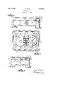
- Figure 1 is a front elevational view, partly in section, of an electrically heated cooking grill of my invention
- Figure 2 is a bottom plan view, partly in section, of the grid-plate, the housing being removed;
- Figure 3 is a partly sectional end side view of the grill.
- A designates the base of the appliance, which preferably comprises a rectangular box-like frame or bed-casting having integrally connected side walls 1 and end Walls 2, the corners of the base A having artistically outwardly flaring depending feet or legs 3 for engaging a table or like support, and a suitable electrical switching device 4 being mounted conveniently on one of the side-walls 1, as best seen in Figure 1.
- the cooking-top of the appliance includes a relatively deep pan-like shell or housing B of (Cl. 21S-37) pressed sheet-metal or the like and comprising a bottom-wall 5 having preferably an integrally connected upstanding slightly flaring side-wall 6 terminating in a continuous pan-encircling curled or outwardly rolled rim 7, the bottom wall 5 flate0 wise resting upon the upper margin of the basewalls 1, 2, to which the housing B is detachably secured by means of angular lugs or clips 8 preferably welded or otherwise integrally connected to the wall 5 and depending therefrom inside the 5 respective base-end-walls 2, suitable fastening elements or screws 9 being passed through the Walls 2 for threadedly engaging the clips 8, as best seen in Figures 1 and 3.
- angular lugs or clips 8 preferably welded or otherwise integrally connected to the wall 5 and depending therefrom inside the 5 respective base-end-walls 2, suitable fastening elements or screws 9 being passed through the Walls 2 for threadedly engaging the clips 8, as
- C designates the grid or cooking-plate proper
- the plate 10 which preferably comprises a flat plate-like casting 10 of aluminum or other suitable metal of relatively high thermal conductivity when compared with the thermal conductivity of the housing B, all the corners and edges of the upper cooking surface of the grid C being preferably carefully rounded for avoiding the formation of grease pockets and the like.
- the plate 10 is provided with an integral marginally raised flange air-space 14 therebetween, as clearly shown in Figures l and 3.
- the housing B is detachably secured to the grid C by means of suitable fastening elements or screws l5 passed through the housing wall 5 for threadedly engaging suitable bosses 16 depending from the underside of the plate 10, as
- the grid-plate 10 On its underside, the grid-plate 10 is formed with a plurality of stiffening and heatdistributing ribs 17, as shown in Figure 2, and also one or more annular walls 18, which latter provide suitable pockets for reception of the grid-heating elements 19 retained therein by respective covers or retainer-plates 20 detachably engaged with the walls 18 by means of suitable fastening elements or screws 21, whereby the elements 19 may with ease and facility be removed for repairs or replacements.
- Suitable conducting elements or Wires 22 lead from the heating elements 19 to a suitable source of electrical energy, preferably through the switch 4, in the usual manner for controlling the actuation of the heating elements.
- a section 23 of asbestos or other suitable material is disposed under the heating elements 19 and over the upper face of the shell'bottom wall 5, as best seen in Figures 1 and 3.
- the housing B fitted as described to the underside of the grid C, serves most effectively for insulating the grid against loss of heat from its underside, and since merely the drip-flange 12 of the grid is exposed at the sides of the housing B, it will be evident that the ow of heat from the non-cooking side or sides of the grid C is substantially reduced and of relatively negligible proportion, ⁇
- a pan-like shell having a base Wall and an upstanding marginal side wall, a cookingplate disposed in parallel relation over the shell base wall and rested marginally on the rim of the shell side Wall, annular pocket-providing ribs on the under face of the plate, heating-elements disposed in said pockets, element retaining plates attached marginally to the ribs and disposed flatwise under the contained elements, and securingscrews engaging the shell and cooking-plate.
- a pan-like shell having a base Wall and an upstanding marginal side Wall, a cooking-plate disposed in parallel relation over the. shell base wall and rested marginally on the rim of the shell side wall, annular pocket-providing ribs on the under face of the plate, heatingelements disposed in said pockets, element retaining plates attached marginally to the ribs and disposed flatwise under the contained elements, and securing-screws engaging the shell and cooking-plate, the plate on its under face being also formed with a plurality of stiffening andheat distributing ribs radiating from the pocket-providing ribs.
Landscapes
- Engineering & Computer Science (AREA)
- Food Science & Technology (AREA)
- Baking, Grill, Roasting (AREA)
Description
Dec. 4, 1934. J, R BURCH y1,982,947
ELECTRIC GRILL Filed Feb. l, 1932 Patented Dec. 4, 1934 UNITED STATES PATENT OFFICE 2 Claims.
'I'his invention relates generally to electrical cooking appliances and has more particular reference to a certain new and useful improvement in electrically-heated grills and the like.
Heretofore, so far as I am aware, electrical cooking grills have been constructed with grids or cooking-plates having relatively deep marginally depending flanges or side walls for enclosing the heating-elements of the appliance. As such grid-side walls are integrally connected with and are hence of the same metal as the grid proper, a very considerable loss of heat from the grid occurs by radiation from the grid-side walls, which heat is wholly lost for cooking purposes, resulting in the uneconomical and inefficient operation of the appliance.
My present invention has hence for its prime objects the provision of an electrical grill having a cooking-top comprising separable elements including a grid and a housing for enclosing the heating-elements, the housing being constructed of a material having a relatively less thermal conductance than that of the grid; the provision, in an appliance of the character set forth, of a grid having its non-cooking sides substantially insulated against loss of heat therefrom; and to generally simplify and improve the construction and efficiency of electrically heated cooking grills.
And with the above and other objects in view, my invention resides in the novel features of form, construction, arrangement, and combination of parts hereinafter described and pointed out in the claims.
In the accompanying drawing,-
Figure 1 is a front elevational view, partly in section, of an electrically heated cooking grill of my invention;
Figure 2 is a bottom plan view, partly in section, of the grid-plate, the housing being removed; and
Figure 3 is a partly sectional end side view of the grill.
Referring now more in detail and by reference characters to the drawing, which illustrates a preferred embodiment of my invention, A designates the base of the appliance, which preferably comprises a rectangular box-like frame or bed-casting having integrally connected side walls 1 and end Walls 2, the corners of the base A having artistically outwardly flaring depending feet or legs 3 for engaging a table or like support, and a suitable electrical switching device 4 being mounted conveniently on one of the side-walls 1, as best seen in Figure 1.
The cooking-top of the appliance includes a relatively deep pan-like shell or housing B of (Cl. 21S-37) pressed sheet-metal or the like and comprising a bottom-wall 5 having preferably an integrally connected upstanding slightly flaring side-wall 6 terminating in a continuous pan-encircling curled or outwardly rolled rim 7, the bottom wall 5 flate0 wise resting upon the upper margin of the basewalls 1, 2, to which the housing B is detachably secured by means of angular lugs or clips 8 preferably welded or otherwise integrally connected to the wall 5 and depending therefrom inside the 5 respective base-end-walls 2, suitable fastening elements or screws 9 being passed through the Walls 2 for threadedly engaging the clips 8, as best seen in Figures 1 and 3.
C designates the grid or cooking-plate proper,
which preferably comprises a flat plate-like casting 10 of aluminum or other suitable metal of relatively high thermal conductivity when compared with the thermal conductivity of the housing B, all the corners and edges of the upper cooking surface of the grid C being preferably carefully rounded for avoiding the formation of grease pockets and the like. The plate 10 is provided with an integral marginally raised flange air-space 14 therebetween, as clearly shown in Figures l and 3.
The housing B is detachably secured to the grid C by means of suitable fastening elements or screws l5 passed through the housing wall 5 for threadedly engaging suitable bosses 16 depending from the underside of the plate 10, as
best shown in Figures 2 and 3, whereby the cooking-top B-C may with convenience and facility be removed as a unit from the base A by simply removing the clip-engaging end-wall screws 9.
On its underside, the grid-plate 10 is formed with a plurality of stiffening and heatdistributing ribs 17, as shown in Figure 2, and also one or more annular walls 18, which latter provide suitable pockets for reception of the grid-heating elements 19 retained therein by respective covers or retainer-plates 20 detachably engaged with the walls 18 by means of suitable fastening elements or screws 21, whereby the elements 19 may with ease and facility be removed for repairs or replacements. Suitable conducting elements or Wires 22 lead from the heating elements 19 to a suitable source of electrical energy, preferably through the switch 4, in the usual manner for controlling the actuation of the heating elements.
And preferably to further prevent o-r retard dissipation and loss of cooking heat from the grid, a section 23 of asbestos or other suitable material is disposed under the heating elements 19 and over the upper face of the shell'bottom wall 5, as best seen in Figures 1 and 3. p
In use and operation, it will be seen that the housing B, fitted as described to the underside of the grid C, serves most effectively for insulating the grid against loss of heat from its underside, and since merely the drip-flange 12 of the grid is exposed at the sides of the housing B, it will be evident that the ow of heat from the non-cooking side or sides of the grid C is substantially reduced and of relatively negligible proportion,`
the resulting conservation of heat being Yeffective for increasing both the heat-storage capacity of thesgrid and the eicient utilization of the heat applied thereto.r v 4 Thesev desirable results are accomplished in my new grill construction in a simple and inexpensive manner, and it `may be stated, in addition, the drip-edge 12, overhanging the housing sidewalls 6, serves effectively for preventing the deposit of drippings thereon; the tight joint between the housing rim 'l and the flange-groove 13 likewise prevents the entry of foreign matter into the air space 14 and thereby protects the heating-elements and Wiring disposed therein; the heat in the grid is evenly distributed and of a uniform character; the grid-flange 11, beingof relatively Qsmall dimensions, may be readily cleaned, and in fact, thegrill in general may sanitary condition. Further, the grid as a whole may be economically manufactured, is compact and durable, and is exceedingly ecient in the performance of its intended functions.
It will be understood that changes and modiiications in the form, construction, arrangement, and combination of the several parts of the grill may be made and substituted for those herein shown and described without departing from the nature andprinciple of my invention. p
Having thus described my invention, what I claim and desire to secure by Letters Patent, s-
1. In a grid, a pan-like shell having a base Wall and an upstanding marginal side wall, a cookingplate disposed in parallel relation over the shell base wall and rested marginally on the rim of the shell side Wall, annular pocket-providing ribs on the under face of the plate, heating-elements disposed in said pockets, element retaining plates attached marginally to the ribs and disposed flatwise under the contained elements, and securingscrews engaging the shell and cooking-plate.
2. In agrid, a pan-like shell having a base Wall and an upstanding marginal side Wall, a cooking-plate disposed in parallel relation over the. shell base wall and rested marginally on the rim of the shell side wall, annular pocket-providing ribs on the under face of the plate, heatingelements disposed in said pockets, element retaining plates attached marginally to the ribs and disposed flatwise under the contained elements, and securing-screws engaging the shell and cooking-plate, the plate on its under face being also formed with a plurality of stiffening andheat distributing ribs radiating from the pocket-providing ribs.
JULIAN R. BURCH.
Priority Applications (1)
| Application Number | Priority Date | Filing Date | Title |
|---|---|---|---|
| US590164A US1982947A (en) | 1932-02-01 | 1932-02-01 | Electric grill |
Applications Claiming Priority (1)
| Application Number | Priority Date | Filing Date | Title |
|---|---|---|---|
| US590164A US1982947A (en) | 1932-02-01 | 1932-02-01 | Electric grill |
Publications (1)
| Publication Number | Publication Date |
|---|---|
| US1982947A true US1982947A (en) | 1934-12-04 |
Family
ID=24361128
Family Applications (1)
| Application Number | Title | Priority Date | Filing Date |
|---|---|---|---|
| US590164A Expired - Lifetime US1982947A (en) | 1932-02-01 | 1932-02-01 | Electric grill |
Country Status (1)
| Country | Link |
|---|---|
| US (1) | US1982947A (en) |
-
1932
- 1932-02-01 US US590164A patent/US1982947A/en not_active Expired - Lifetime
Similar Documents
| Publication | Publication Date | Title |
|---|---|---|
| CN107006080B (en) | High performance electric oven, method and heat radiation module | |
| US2523796A (en) | Portable roaster and broiler | |
| US2811099A (en) | Rotisserie | |
| US3581654A (en) | Vertical electric grill unit | |
| US2392208A (en) | Portable scrubbing bucket | |
| US2691717A (en) | Electrical appliance heater | |
| US2840684A (en) | Combination frying pan and griddle and method of heating the operative surface thereof | |
| US6867394B2 (en) | Roasting oven with dual heating elements | |
| US2675458A (en) | Electric cooking utensil | |
| US3141090A (en) | Portable heating trays | |
| US3489880A (en) | Selectively heated chafing dish | |
| US1982947A (en) | Electric grill | |
| US2147319A (en) | Electric culinary appliance | |
| US2920615A (en) | Culinary device | |
| US2518015A (en) | Portable electric stove | |
| US2230268A (en) | Broiler and fryer unit | |
| US2553974A (en) | Portable tray and heater | |
| CN209863501U (en) | Electric oven with air frying function | |
| US2217804A (en) | Domestic appliance | |
| GB459764A (en) | Improvements in and relating to grilling apparatus | |
| US2291359A (en) | Cooking device | |
| US3590214A (en) | Paint softener | |
| US3683792A (en) | Electric barbeque unit | |
| US2177230A (en) | Electric oven | |
| US1014161A (en) | Electrical heater. |