US1982902A - Feeding mechanism - Google Patents
Feeding mechanism Download PDFInfo
- Publication number
- US1982902A US1982902A US521637A US52163731A US1982902A US 1982902 A US1982902 A US 1982902A US 521637 A US521637 A US 521637A US 52163731 A US52163731 A US 52163731A US 1982902 A US1982902 A US 1982902A
- Authority
- US
- United States
- Prior art keywords
- hopper
- shaft
- button
- rotary
- machine
- Prior art date
- Legal status (The legal status is an assumption and is not a legal conclusion. Google has not performed a legal analysis and makes no representation as to the accuracy of the status listed.)
- Expired - Lifetime
Links
Images
Classifications
-
- A—HUMAN NECESSITIES
- A41—WEARING APPAREL
- A41H—APPLIANCES OR METHODS FOR MAKING CLOTHES, e.g. FOR DRESS-MAKING OR FOR TAILORING, NOT OTHERWISE PROVIDED FOR
- A41H37/00—Machines, appliances or methods for setting fastener-elements on garments
- A41H37/10—Setting buttons
-
- Y—GENERAL TAGGING OF NEW TECHNOLOGICAL DEVELOPMENTS; GENERAL TAGGING OF CROSS-SECTIONAL TECHNOLOGIES SPANNING OVER SEVERAL SECTIONS OF THE IPC; TECHNICAL SUBJECTS COVERED BY FORMER USPC CROSS-REFERENCE ART COLLECTIONS [XRACs] AND DIGESTS
- Y10—TECHNICAL SUBJECTS COVERED BY FORMER USPC
- Y10T—TECHNICAL SUBJECTS COVERED BY FORMER US CLASSIFICATION
- Y10T29/00—Metal working
- Y10T29/53—Means to assemble or disassemble
- Y10T29/53539—Means to assemble or disassemble including work conveyor
Definitions
- the edge of th ro tener feeding mechanism for button attach ng member is provided with a series of apertures 20 machines and the like, and among other objects which permit the escape of fasteners only when aims to improve the utility and emciency'o ,mec'h arranged so that the pr s thereof pas u h anism of this character. the apertures and the heads through the space 19. 60
- Fig. 4 is .a section of the button hopper taken qu'ate spuce 19 tor the passage o th f s n 15 on the plane440f Fig.2; y heads.
- The" upper member l5 is made longi- Fig. 5 is an enlarged elevation of a detail 01 the tudinally outwardly slidable on shaft 2; to perperiphery of the rothry element in the button mit discharge of the contents of the h pper and hopper showing the button outlets; the outer wall of the rotary hopper is recessed as Fig 6 is a similar elevation showing fastener at 2'7 for this purpose.
- the hopper is key d to so outlet Passage t e tastener h p e the shaft to effect its rotation by a pin 28 engag- Fig; "lisa vertical sectionsimllartothat shown inc in one of a series of recesses or ratchet in Fig. 2 .of a diflerent form of feeding mechanotches 29 in a driving element 30 secured to m; v and associated with he stop 31 which is pinned 30 Fig. 8 is aplan secti'ontoken n th Plane .8' at 32 to :the shaft. Engagement of the pin 28 85 of Fig. 7 showing a detail of a h pper adjusting with the face of.
- Fig. 9 is an elevation, partly in section, showing when .the pin 28 is withdrawn, the enga emen ahopper c1utch;.and 7 of the wall of the recess 27 with the stop ,31 35
- Fig. 10 is a. perspective view of a hopperletch limi s the outward travel of thehopper. Qui k 90 bar.
- v 1 detachment of the hopper from the shaft is The inventive vteedins me ha ismi he h w effected by making the pin 28 longitudinally embodied in a button attaching machine to'sup slidable in the hopper l5 and pressing it into a ply buttons and fasteners throug raceways l1 notch 291ml means of a pring 33 which is con- 40 and 12 to button attaching mechanism indicated fined between the collar 34 on the pin vand the 9 generally at 13c.
- Buttons are supplied from a. similar though.
- buttons are'held in the raceway in a predetermined position and'in such predetermined position are delivered to the button placing and attaching mechanism.
- the rotary hopper member 39 is detachably keyed to shaft 24 by devices similar to those described in connection with the fastener hopper,
- buttons may be easily drawn outwardly on the shaft to effect a quick discharge of the buttons.
- Quick discharge of the buttons is even more important than the fasteners inasmuch as the variety of buttons of the same size attached by a given style of machine may be very great and it is very important to avoid such necessary to pass the buttons through the machine in order to discharge the hopper. Aside from the inevitable marring of the buttons by the latter operation, it would also be very time Filling of the button and fastener hoppers may be effected through passages 41 and 42 normally covered by the hinged covers 43 and 44.
- Figs. 7 to 10, inclusive is illustrated a different form of fastener and button hopper mechanism embodying additional features not shown inlthe arrangement previously described.
- the ratchet drive comprises a pair of ratchet elements 49 and 50 having interfitting ratchet teeth, the former loose upon and the latter pinned to drive shaft 47.
- the ratchet element 49 is maintained in yielding engagement with the companion element 50 by a spring 51 carried between it and a shoulder 52 on the hub 53 of the rotating hopper, with which the ratchet element is drivingly connected by a tongue 54 slidtons, fasteners and other foreign matter.
- the rotary hoppers may 'be'moved outwardly .to, discharge buttons or fasteners or to release a jam; and for this purpose a latch 58 is "provided on, each hopper cone for quickly releasing the hopper.
- a spring 59 normally presses the end 60 of the latch into a groove'61 'onthe shaft 47., The engagement of the "latch in groove 61 not only prevents outward movement of the hopp'erbut maintains the proper space 63 between the rotary portion of the hopper and the stationary structure and through which the heads of the buttons or fasteners escape.
- the driving elements When movedoutwardly on the shaft, separationbetween the driving elements occurs at the ratchet butthe plates are clamped together to effect an adequate 'frictionalengagement with the sprocket by screws 77.
- the frictional engagement with the sprocket is sufficient. to insure-rotation of the hoppers under ordinary conditions, but if a button orf'astener 'jams in the hopper mecha- I, nism.fdamage'to'themachine is avoided by slip- Ipagejof thefdriving sprocket 73.
- the hoppers may. be filled through the passages 78 and 79, respectively. which are'provided with coversinot shownllj s I .'I
- the subject matter of the hopper mechanism illustrated in Figs. 1 'to 6, "inclusive has been di- Sprocket 73 vided from my copending application Serial No. 565,420, filed June 2, 1922, and the subject matter of the hopper mechanism shown in Figs. '7 to 10, inclusive, has been divided from my copending application Serial No. 30,686, filed. May 16, 1925.
- the combination comprising a feeding hopper having a rotary portion whose free edge is spaced from the fixed portion of said hopper toprovide a space for the discharge of articles from said hopper, and an eccentric adjusting pin for moving said rotating portion to adjust the width of said space.
- a hopper In abutton attaching machine, the combination of a hopper, driving mechanism therefor, including a drive shaft, and quickly detachable means for connecting the hopper to said drive shaft in direct driving relation therewith and which also keys the hopper thereon against longitudinal movement with respect to said drive shaft.
- the combination comprising a hopper drive shaft, a rotary hopper mounted on said shaft and longitudinally slidable thereon, a device for connecting said hopper to said shaft and to hold the hopper against longitudinal movement on said shaft, and means for releasing said device to permit said hopper to be moved longitudinally on said shaft to discharge its contents.
- the combination comprising a stationary hopper housing, a hopper shaft, a rotary feeding hopper longitudinally slidable and spaced from said housing to provide an aperture for the feeding of articles from the hopper, a locking pin engaging said shaft for holding said hopper in proper position g on said shaft and releasable topermit said hopper to slide outwardly on said shaft to discharge the contents of the hopper, and an eccentric bushing around said pin and rotatable to shift said pin relative to said hopper to adjust the feeding aperture.
- the combination comprising a stationary hopper housing, a hopper shaft, a rotary feeding hopper longitudinally slidable and spaced from said housing to provide an aperture for the feeding of articles from the hopper, a locking member for holding said hopper in proper position on said shaft and releasable to permit said hopper to slide outwardly on said shaft to discharge the contents of the hopper, and means for adjusting said lock inwardly or outwardly relative to said stationary hopper housing to vary the size of the feeding aperture.
- the combination comprising a hopper shaft, a rotary hopper slidable on said shaft and movable outwardly to permit the discharge of the contents of the hopper, a releasable lock for holding said 8.
- combination comprising a rotating feeding hopper, a driving ratchet therefor inside said hopper and arranged to permit rotation of said hopper independently thereof, and a guard for said ratchet to protect the same from the contents of said hopper.
- the combination comprising a rotary hopper mounted on a shaft and slidable longitudinally thereof, a latch operable in a recess for holding said hopper in a definite position on said shaft and movable out of said recess to permit said hop-per to be moved on said shaft to discharge its contents, a check to limit the movement of said hopper on said shaft, and a spring to return said hopper to normal position.
- the combination comprising a stationary hopper housing, a rotary hopper mounted on a shaft and slidable longitudinally thereof to withdraw the same from operative relation to its housing 1 to permitthe discharge of its contents, a stop to limit its movement on said shaft, and a spring to return it to normal position.
- a button attaching machine comprising a rotary shaft, hopper housings, a plurality of supply hoppers mounted to rotate on said shaft and being slidable outwardly relative to their respective housings to discharge their contents, said hoppers having apertures associated therewith constructed and arranged to permit the escape of articles therein when in predetermined position, means for rotating said shaft to drive the hoppers, means for detachably securing said hoppers to said rotary shaft in operative position and releasable to permit the outward movement of said hoppers, and means for limiting the outward movement of said hoppers to prevent complete detachment thereof.
- a button attaching machine comprising a rotary shaft, a supply hopper mounted to rotate coaxially with said shaft, said hopper having apertures associated therewith constructed and arranged to permit the escape of its contents when in predetermined position, means for rotating said shaft, and positive clutch means for securing said hopper to said rotary shaft whereby the latter may be positively rotated in one direction, said means automatically permitting the manual rotation of said hopper independently of the rotation of said shaft while maintaining the operative driving connection with the shaft.
Description
Dec. 4, 1 934. CLARK 1,982,902
FEEDING MECHANISM Filed March 11, 1931 5 Sheets-Sheet l May/41 wwiw QmMMLQAWQ MM Dec. 4, 1934. 1 LARK 1,982,902
* FEEDING MECHANISM Filed March 11, 1931 3 Sheets-Sheet 2 we /A gwwnto cr Dec. 4, 1934. M LARK 1,982,902
FEEDING MECHANI SM Filed March 11, 1951 3 Sheets-Sheet 3 Patented Dec. 4, 1934 .9mm mcpmd'mncnmsm John M. Emit, Det it, Michn aseisn r to Un versal Button Fastening & Button Compo y, Detro t, Mich, a corporation of Michigan Application March 1 1, 1931, semi No. 521,637 r In Canada; September 28, 1029 1-2 Claim; (01. era -12 This invention relates to button and .button.ash ads ar an ed flat-wise. The edge of th ro tener feeding mechanism for button attach ng member is provided with a series of apertures 20 machines and the like, and among other objects which permit the escape of fasteners only when aims to improve the utility and emciency'o ,mec'h arranged so that the pr s thereof pas u h anism of this character. the apertures and the heads through the space 19. 60
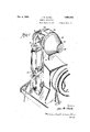
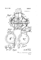
The nature of the invention may be readily In such predetermined position the Iasteners inunderstood by reference to a machine mbodying dicated at 2.1 may pas down th rac y 12 the same and illustrated in the accompanying which is arranged tangentially with the rim of d wi the rot ry m mber 5 and which has a slot 22 In said drawingsz' throu h which the fastener legs ext ndh 65 l is a p rspective, of a button at aohing present Iastener hoppe s des gned to permi t e machine embodying the inventive feeding mechpassage of double prongecl iast ner and th Slot anism; 22 mainto sth prongs in alinement f p p Fi 2 is a vertical central section t roug th delivery t themacing and attach n m s button and Iastener feeding hopp rs and asso- The rotary hoppe member 5 is mounted for 79 ciated mechanism; t '1 rotation upon a drive shelft 24 wh c P s Fi 3 is a section taken along the p an li through an ooeni sln the hub 25 of the h pperof F g, 2 showing a portion of the inte i of h As shown the hub 25 abuts a ainst the stationary tastener hopper and Ia tenermceway; hub 26 to assure-the maintenance of an ade- Fig. 4 is .a section of the button hopper taken qu'ate spuce 19 tor the passage o th f s n 15 on the plane440f Fig.2; y heads. The" upper member l5 is made longi- Fig. 5 is an enlarged elevation of a detail 01 the tudinally outwardly slidable on shaft 2; to perperiphery of the rothry element in the button mit discharge of the contents of the h pper and hopper showing the button outlets; the outer wall of the rotary hopper is recessed as Fig 6 is a similar elevation showing fastener at 2'7 for this purpose. The hopper is key d to so outlet Passage t e tastener h p e the shaft to effect its rotation by a pin 28 engag- Fig; "lisa vertical sectionsimllartothat shown inc in one of a series of recesses or ratchet in Fig. 2 .of a diflerent form of feeding mechanotches 29 in a driving element 30 secured to m; v and associated with he stop 31 which is pinned 30 Fig. 8 is aplan secti'ontoken n th Plane .8' at 32 to :the shaft. Engagement of the pin 28 85 of Fig. 7 showing a detail of a h pper adjusting with the face of. the stop Bl prevents ou ward device; movement of the hopper during operation, and Fig. 9 is an elevation, partly in section, showing when .the pin 28 is withdrawn, the enga emen ahopper c1utch;.and 7 of the wall of the recess 27 with the stop ,31 35 Fig. 10 is a. perspective view of a hopperletch limi s the outward travel of thehopper. Qui k 90 bar. v 1 detachment of the hopper from the shaft is The inventive vteedins me ha ismi he h w effected by making the pin 28 longitudinally embodied in a button attaching machine to'sup slidable in the hopper l5 and pressing it into a ply buttons and fasteners throug raceways l1 notch 291ml means of a pring 33 which is con- 40 and 12 to button attaching mechanism indicated fined between the collar 34 on the pin vand the 9 generally at 13c. removable plug Thus when the pin is with- In the present arrangement, ,fas enerswhioh drawn so that it clears the stop .31 the hopper embody heads and attaching prongs are supplied is not only disconnected from the driving shajt from a fastener hopper indicated at 14 .a d mbut it may be moved outwardly to discharge its rising a rotary conical haped hopp m e contents. In order to empty he hopper it is loo 15 which, with the recess 6 in the stationary not necessary, th refore. to un the fasten rs frame of the machine Prov des an en l u 0 through th machine with the po sibility o disthe fasteners. The ,rim ,18 of tnevr t y m m e tortion or mutilation. This is particular y dents with'the cir ular mon h 117 of the stationar sirable because ne ma h ne may emnloy a ostructure sumciently close'l to ex lude ast e sriety of fasteners of th sam s z wh a y 105 Th d e of the rotary memb r 15 issoaoed a as to style i head a d plat ng or coating. Redistance indicated at .19 irom the pposi a totion o t e h p e is ef ec d by sprocket chain of the stationary portion of the hopper to pro- 36 which passes around asprocket on drive shaft vide-a passage for the heads or the fasteners; and 24. In the event a iastener should become (to assure the discharge of the Iastenenswith their' jammed betwe n the stati nary and mova A10 in the event it should become necessaryto, dislodge an improperly placed fastener, or for other reasons. hopper, the pin or catch 28 merely rides in and out of the successive notches 29.
Buttons are supplied from a. similar though.
somewhat differently shaped hopper -37 advan tageously operated by the same shaft 24 and 10-- cated on the opposite side of the machine. The space 38 between the stationary portion of the hopper structure and the rotating hopper element 39 is, of course, adjusted to permit the passage of the button heads and the adjacent rim of the hopper member 39 is formed with passages'40 shaped to permit the passage of the collet or neck portion of the button. Thus buttons can escape consuming.
only when arranged with their heads in the space 38 and'their collets or'necks in one of the passages. 40 on the rotary hopper member 39. In this position they may pass out into the button raceway 11 which is arranged tangentiallyto the hopper. The buttons are'held in the raceway in a predetermined position and'in such predetermined position are delivered to the button placing and attaching mechanism. g
The rotary hopper member 39 is detachably keyed to shaft 24 by devices similar to those described in connection with the fastener hopper,
and the former may be easily drawn outwardly on the shaft to effect a quick discharge of the buttons. Quick discharge of the buttons is even more important than the fasteners inasmuch as the variety of buttons of the same size attached by a given style of machine may be very great and it is very important to avoid such necessary to pass the buttons through the machine in order to discharge the hopper. Aside from the inevitable marring of the buttons by the latter operation, it would also be very time Filling of the button and fastener hoppers may be effected through passages 41 and 42 normally covered by the hinged covers 43 and 44.
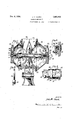
In Figs. 7 to 10, inclusive, is illustrated a different form of fastener and button hopper mechanism embodying additional features not shown inlthe arrangement previously described. In
this arrangement the fastener and button hoppers 45 and 46, respectively, are driven'from shaft 47 through a ratchet device 48 which permits rotation of the hoppers in their normal direction of rotation independently of the drive attaching dies. 'The ratchetjarra'ngement also makes it convenient tofldesign, the hopper drive to operate only while the machine is actually motor may nevertheless be running. In such cases, upon. stopping'the attaching mechanism the inertia in the rotating hoppers is spent'mere- During such manual operation of the adjustment. 3 marring of the buttons'as'would occur if it were ly in a short continued rotation and is not transmitted back to the attaching mechanism with the possible result of moving the parts beyond their proper stopping position (i. e. with the attaching dies open or separated). With this sortlpf hopper drive, marring of the buttons threugh excessive rotation of the hopper is avoided- The ratchet drive comprises a pair of ratchet elements 49 and 50 having interfitting ratchet teeth, the former loose upon and the latter pinned to drive shaft 47. The ratchet element 49 is maintained in yielding engagement with the companion element 50 by a spring 51 carried between it and a shoulder 52 on the hub 53 of the rotating hopper, with which the ratchet element is drivingly connected by a tongue 54 slidtons, fasteners and other foreign matter.
The rotary hoppers may 'be'moved outwardly .to, discharge buttons or fasteners or to release a jam; and for this purpose a latch 58 is "provided on, each hopper cone for quickly releasing the hopper. A spring 59 normally presses the end 60 of the latch into a groove'61 'onthe shaft 47., The engagement of the "latch in groove 61 not only prevents outward movement of the hopp'erbut maintains the proper space 63 between the rotary portion of the hopper and the stationary structure and through which the heads of the buttons or fasteners escape. Proper adjustment of this space to the thickness of button or I fastener heads is effected by rotating the eccentric bushing '64 through which the latch 58passes and thereby moving the rotating porti'on'of the hopper in or out relatively to the stationary portion. A set screw 65 maintains the The hopper. maybe released as aforesaid by for;
raising the latch" through its handle 66 until it clears groove'61'. The outward movement of the hopper islimited by. a'stop in the'iform of a headed rod '67 whose head 68 engages the face of the hopper and whose inner'end' 69 is made larger. than the plug 70. screwed into the hopper drive shaft 47 through which the rod passes.
A spring 71' confined between the enlarged end 69 of the rod and theplug .70 normally tendsto move the hopper inwardly. When movedoutwardly on the shaft, separationbetween the driving elements occurs at the ratchet butthe plates are clamped together to effect an adequate 'frictionalengagement with the sprocket by screws 77. The frictional engagement with the sprocketis sufficient. to insure-rotation of the hoppers under ordinary conditions, but if a button orf'astener 'jams in the hopper mecha- I, nism.fdamage'to'themachine is avoided by slip- Ipagejof thefdriving sprocket 73. attaching buttons and not "during idle periods of the attaching mechanis'm'when the driving .The hoppers may. be filled through the passages 78 and 79, respectively. which are'provided with coversinot shownllj s I .'IThe subject matter of the hopper mechanism illustrated in Figs. 1 'to 6, "inclusive has been di- Sprocket 73 vided from my copending application Serial No. 565,420, filed June 2, 1922, and the subject matter of the hopper mechanism shown in Figs. '7 to 10, inclusive, has been divided from my copending application Serial No. 30,686, filed. May 16, 1925.
Obviously the invention is not limited to the details of construction herein shown and described since these may be variously modified. Moreover it is not indispensable that all features of the invention be used conjointly, since all features may be advantageously employed in various combinations and subcombinations.
Having described my invention, I claim:
1. In a machine of the character described, the combination comprising a feeding hopper having a rotary portion whose free edge is spaced from the fixed portion of said hopper toprovide a space for the discharge of articles from said hopper, and an eccentric adjusting pin for moving said rotating portion to adjust the width of said space.
2. In abutton attaching machine, the combination of a hopper, driving mechanism therefor, including a drive shaft, and quickly detachable means for connecting the hopper to said drive shaft in direct driving relation therewith and which also keys the hopper thereon against longitudinal movement with respect to said drive shaft.
3. In an attaching machine of the character described, the combination comprising a hopper drive shaft, a rotary hopper mounted on said shaft and longitudinally slidable thereon, a device for connecting said hopper to said shaft and to hold the hopper against longitudinal movement on said shaft, and means for releasing said device to permit said hopper to be moved longitudinally on said shaft to discharge its contents.
4. In a machine of the character described, the combination comprising a stationary hopper housing, a hopper shaft, a rotary feeding hopper longitudinally slidable and spaced from said housing to provide an aperture for the feeding of articles from the hopper, a locking pin engaging said shaft for holding said hopper in proper position g on said shaft and releasable topermit said hopper to slide outwardly on said shaft to discharge the contents of the hopper, and an eccentric bushing around said pin and rotatable to shift said pin relative to said hopper to adjust the feeding aperture.
5. In a machine of the character described, the combination comprising a stationary hopper housing, a hopper shaft, a rotary feeding hopper longitudinally slidable and spaced from said housing to provide an aperture for the feeding of articles from the hopper, a locking member for holding said hopper in proper position on said shaft and releasable to permit said hopper to slide outwardly on said shaft to discharge the contents of the hopper, and means for adjusting said lock inwardly or outwardly relative to said stationary hopper housing to vary the size of the feeding aperture.
6. In a machine of the character described, the combination comprisinga hopper shaft, a rotary hopper slidable on said shaft and movable outwardly to permit the discharge of the contents of the hopper, a releasable lock for holding said 8. In a machine of the character described, the
combination comprising a rotating feeding hopper, a driving ratchet therefor inside said hopper and arranged to permit rotation of said hopper independently thereof, and a guard for said ratchet to protect the same from the contents of said hopper.
9. In a machine of the character described, the combination comprising a rotary hopper mounted on a shaft and slidable longitudinally thereof, a latch operable in a recess for holding said hopper in a definite position on said shaft and movable out of said recess to permit said hop-per to be moved on said shaft to discharge its contents, a check to limit the movement of said hopper on said shaft, and a spring to return said hopper to normal position.
10. In a machine of the character described, the combination comprising a stationary hopper housing, a rotary hopper mounted on a shaft and slidable longitudinally thereof to withdraw the same from operative relation to its housing 1 to permitthe discharge of its contents, a stop to limit its movement on said shaft, and a spring to return it to normal position.
11. In a button attaching machine, the combination comprising a rotary shaft, hopper housings, a plurality of supply hoppers mounted to rotate on said shaft and being slidable outwardly relative to their respective housings to discharge their contents, said hoppers having apertures associated therewith constructed and arranged to permit the escape of articles therein when in predetermined position, means for rotating said shaft to drive the hoppers, means for detachably securing said hoppers to said rotary shaft in operative position and releasable to permit the outward movement of said hoppers, and means for limiting the outward movement of said hoppers to prevent complete detachment thereof.
12. In a button attaching machine, the combination comprising a rotary shaft, a supply hopper mounted to rotate coaxially with said shaft, said hopper having apertures associated therewith constructed and arranged to permit the escape of its contents when in predetermined position, means for rotating said shaft, and positive clutch means for securing said hopper to said rotary shaft whereby the latter may be positively rotated in one direction, said means automatically permitting the manual rotation of said hopper independently of the rotation of said shaft while maintaining the operative driving connection with the shaft.
JOHN M. CLARK.
Applications Claiming Priority (1)
| Application Number | Priority Date | Filing Date | Title |
|---|---|---|---|
| CA1982902X | 1929-09-28 |
Publications (1)
| Publication Number | Publication Date |
|---|---|
| US1982902A true US1982902A (en) | 1934-12-04 |
Family
ID=4174638
Family Applications (1)
| Application Number | Title | Priority Date | Filing Date |
|---|---|---|---|
| US521637A Expired - Lifetime US1982902A (en) | 1929-09-28 | 1931-03-11 | Feeding mechanism |
Country Status (1)
| Country | Link |
|---|---|
| US (1) | US1982902A (en) |
Cited By (5)
| Publication number | Priority date | Publication date | Assignee | Title |
|---|---|---|---|---|
| US2938831A (en) * | 1957-09-06 | 1960-05-31 | American Cyanamid Co | Control of nematodes using dialkyl pyrazinyl phosphorothioates |
| US3026245A (en) * | 1959-06-18 | 1962-03-20 | American Cyanamid Co | Method of controlling nematodes employing thiothiazolines |
| US3292249A (en) * | 1964-07-10 | 1966-12-20 | Curtis Helene Ind Inc | Machine for assembling two-piece overcaps |
| US3471915A (en) * | 1966-12-30 | 1969-10-14 | Western Electric Co | Apparatus for selectively feeding and assembling card components of different types |
| EP1537797A1 (en) * | 2003-12-05 | 2005-06-08 | Gaetano Raccosta | Quickly-coupled delivery device for automatic machines for applying buttons and other metal fittings on a support and machine including the delivery device |
-
1931
- 1931-03-11 US US521637A patent/US1982902A/en not_active Expired - Lifetime
Cited By (5)
| Publication number | Priority date | Publication date | Assignee | Title |
|---|---|---|---|---|
| US2938831A (en) * | 1957-09-06 | 1960-05-31 | American Cyanamid Co | Control of nematodes using dialkyl pyrazinyl phosphorothioates |
| US3026245A (en) * | 1959-06-18 | 1962-03-20 | American Cyanamid Co | Method of controlling nematodes employing thiothiazolines |
| US3292249A (en) * | 1964-07-10 | 1966-12-20 | Curtis Helene Ind Inc | Machine for assembling two-piece overcaps |
| US3471915A (en) * | 1966-12-30 | 1969-10-14 | Western Electric Co | Apparatus for selectively feeding and assembling card components of different types |
| EP1537797A1 (en) * | 2003-12-05 | 2005-06-08 | Gaetano Raccosta | Quickly-coupled delivery device for automatic machines for applying buttons and other metal fittings on a support and machine including the delivery device |
Similar Documents
| Publication | Publication Date | Title |
|---|---|---|
| US3750925A (en) | Snap attaching apparatus | |
| US1982902A (en) | Feeding mechanism | |
| US2523388A (en) | Top stop attaching machine | |
| DE1436716B2 (en) | CONTROL DEVICE FOR THE INDEPENDENT LINE-ACCURATE STOPPING OF A PAPER TRAIL | |
| DE882671C (en) | Device for the transport of prepared mass particles, such as buttons or the like. | |
| US1165078A (en) | Fastener assembling and attaching means. | |
| US2261281A (en) | Orienting button-attaching machine | |
| US2244667A (en) | Machine for making fasteners | |
| US1913648A (en) | Feed mechanism for attaching machines | |
| US1879895A (en) | Attaching machine | |
| US1534273A (en) | Vending machine | |
| US2244425A (en) | Die casting machine | |
| DE706818C (en) | Nailing device, especially for heel lasting machines | |
| US1807941A (en) | Feeding mechanism for riveting machines | |
| US1767513A (en) | Machine for sorting and setting fasteners | |
| US4137621A (en) | Apparatus and method of applying staple-like bottom stops to slide fasteners and the like | |
| US1711155A (en) | Automatic coal-spout-swinging device | |
| DE503342C (en) | Device for automatic grouping | |
| US1598429A (en) | Hat-former feeder | |
| JP2879230B2 (en) | Screw driving device | |
| US2245727A (en) | Hopper feed control mechanism for slide fastener stringer forming apparatus | |
| SU121386A1 (en) | Machine for attaching the top of the buttons in the shoe blank | |
| DE815937C (en) | Machine for putting on and clamping the beginning and end parts of a zipper | |
| DE2246343C3 (en) | Continuously working machine for filling mastic putty into lamp bases | |
| DE2010734A1 (en) | Feeding device for stoppers on champagne bottles |