US1979237A - Laundry machine - Google Patents
Laundry machine Download PDFInfo
- Publication number
- US1979237A US1979237A US502079A US50207930A US1979237A US 1979237 A US1979237 A US 1979237A US 502079 A US502079 A US 502079A US 50207930 A US50207930 A US 50207930A US 1979237 A US1979237 A US 1979237A
- Authority
- US
- United States
- Prior art keywords
- tubs
- containers
- shaft
- frame
- washing
- Prior art date
- Legal status (The legal status is an assumption and is not a legal conclusion. Google has not performed a legal analysis and makes no representation as to the accuracy of the status listed.)
- Expired - Lifetime
Links
- 238000005406 washing Methods 0.000 description 55
- 230000007246 mechanism Effects 0.000 description 17
- 239000011435 rock Substances 0.000 description 10
- XLYOFNOQVPJJNP-UHFFFAOYSA-N water Substances O XLYOFNOQVPJJNP-UHFFFAOYSA-N 0.000 description 9
- 239000000243 solution Substances 0.000 description 6
- 238000010276 construction Methods 0.000 description 4
- 238000000605 extraction Methods 0.000 description 3
- 230000005484 gravity Effects 0.000 description 3
- 230000000994 depressogenic effect Effects 0.000 description 2
- 238000004900 laundering Methods 0.000 description 2
- 239000007788 liquid Substances 0.000 description 2
- 239000002184 metal Substances 0.000 description 2
- 230000000284 resting effect Effects 0.000 description 2
- 101150096839 Fcmr gene Proteins 0.000 description 1
- 230000000881 depressing effect Effects 0.000 description 1
- 238000003780 insertion Methods 0.000 description 1
- 230000037431 insertion Effects 0.000 description 1
- 238000000034 method Methods 0.000 description 1
- 230000010355 oscillation Effects 0.000 description 1
- 230000002093 peripheral effect Effects 0.000 description 1
- 230000000717 retained effect Effects 0.000 description 1
- 239000012487 rinsing solution Substances 0.000 description 1
- 239000000344 soap Substances 0.000 description 1
- 239000000725 suspension Substances 0.000 description 1
Images


Classifications
-
- D—TEXTILES; PAPER
- D06—TREATMENT OF TEXTILES OR THE LIKE; LAUNDERING; FLEXIBLE MATERIALS NOT OTHERWISE PROVIDED FOR
- D06F—LAUNDERING, DRYING, IRONING, PRESSING OR FOLDING TEXTILE ARTICLES
- D06F23/00—Washing machines with receptacles, e.g. perforated, having a rotary movement, e.g. oscillatory movement, the receptacle serving both for washing and for centrifugally separating water from the laundry
Definitions
- My invention relates to a laundry machine, and particularly, to a laundry machine in which a washing machine, an extractor, and a tumbler are all combined in one apparatus and drivenby a single source of power.
- clothes going through the laundering process have necessarily been handled about eight times, namely, from the'assortin'g tables to suitable transfer containers, from such con- 'V10 tainers to the cylinder of the washing machine,
- the objects of my invention are'to assemble a. plurality of removable and interchangeable cylinders or lcontainers about a central vertical pivot and have the cylinders or containers so constructed and mounted as to serve as'the cylinders in a washing machine, as the baskets in an extracting machine, and as the tumbling containers in a tumbling machine; to provide a device serving as a combined extractor and tumbler wherein y the tumbling operation and the ⁇ extracting operation willy start working together thereby tending to balance the load for final extraction, to so arrange the driving mechanism that the tumbling operation will automatically balance the load before the extracting operation reaches its highest point and toso arrange the driving mechanism that the tumbling operation will start before the extraction operation comes to a stop;'to provide a single control means for, causing the operation of the machine as a washer, an extractor, or atumbler, the apparatus belng such that the operation of the machine may be changed fromv floor space will be conserved and much
- Fig. 1 is a plan view, partly broken away, showing a machine embodying my invention
- Fig. 2 is a view partly in section and partly in elevation of the machine shown in Fig. 1
- Fig. 3 is a plan view of the machine with the top cover removed and with parts omitted for purposes of illustration
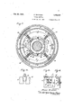
- Fig. 4 is a sectional View showing the driving mechanism and holders for one of the clothes containers used in conjunction with this apparatus
- Fig. 5 is a sectional view of the upper part of the device and showing the driving mechanism for operating its parts
- Fig. 6 is an elevation, partly broken away, showing one of the cylinders or containers
- Figs. 7, 8 and 9 are sec-Y tional views, and elevations of both ends of one of-the cylinders or containers
- Fig. 10 is a fragmentary sectional view showing the outlet valve for the cylinder or container shown in Fig. 6 together with a means for operating the valve;
- Fig. 11 is a view taken on the line 11-11 of Fig. 5, showing brake and clutch mechanism;
- Fig. 12 is a view taken on the line 12-12 of Fig. 11;
- Fig. 13 is a view taken on the line 13--13 of Fig.v 11;
- Fig. 14 is a view taken on the line 14--14 of 'zor Fig. 13;
- Fig. 15 is a partly diagrammatical detail view showing the motor circuit switches operable by thebrake and clutch mechanism;
- Fig. 16V is a face view of the timing apparatus as embodied in my invention.
- a vertical shaft 8 is centrally disposed within the outer casing just described and is rotatably mounted, being supported at its lower end in a bearing 9 provided in the bottom 1 of the casing as shown in Fig. 4 and at its upper end in a bearingv 10 in the top 3 of the casing.
- a triad frame 11 is mounted on the shaft 8 so as to normally rest against a shoulder 12 at the bottom of the shaft and is keyed thereto, the triad frame supporting three tubs 13 arranged symmetrically abou ⁇ t the shaft 8 within the outer casing in such manner that the tubs are free to travel in alcircular path when the shaft 8 is rotated.
- Each tub 13 is provided with bearings 14 and 15 in its opposing vertical walls and in axial alignment with each other, the common axis of the bearings extending' horizontally and radially outwardly from the shaft 8.
- Each tub is provided with a circular clamping disk 16 adjacent the wall of the tub remote from the shaft 8 and provided with a trunnion 17 rotatably mounted in the bearing 14, and with a similar vertically disposed circular clamping disk 18 adjacent the opposite Wall of the tub and provided witha trunnion 19 rotatably mounted in the bearing 15.
- the trunnion 19 is such as to be capable of a longitudinal movement within the bearing 15 so that the space between the disk 16 and the disk 18 can be varied for the purpose of releasing and clamping a container cylinder 20 as shown in Figs. 4, '7, 8 and 9 therebetween.
- the housing of the bearing 15 is provided with diametrically opposed radially extending pins 21 which extend within the forked ends of an arm 22 that is rigidly mounted on a rock shaft 23 supported in suitable bearingson the outer surface of the adjacent wall of the tub 13.
- an arm 24 is rigidly secured .to the rock shaft 23 on the outside of the casing, the free end of the arm 24being pivotally connected to a link 25 which is, in turn, pivotally connected at its opposite end to a hand lever 26 that is pivoted as at 27 to one wall of the outer casing.
- The. uppermost end of the hand lever 26 is provided with the usual holding catch 28 that cooperates with a rack 29 to retain the lever in its operated position wherein the clamping disk 18 will be in one of two positions, namely, a position which will permit insertion of a cylinder or container 20 between the clamping disks .16 and 18 or a position wherein the cylinder-'or container will be tightly held between the clamping disks.
- both clamping disks 16 and 18 are provided with laterally extending circular flanges 3 0 on their opposing edges which are arranged to extend over the circular ends of the cylinders or ⁇ containers 20 and hold the cylinders or containers between the disks.
- Such containers are removable from between the disks 16 and 18 when the upper end of the hand lever is moved in a direction towards the central shaft 8 which will also move the forkedv end of the arm 22. toward the central shaft and the disk 18 away from the disk 16.
- the lower half circle of the lateral flanges 30 extend further outwardly from the faces of the disks than the upper half circle of the anges asis clearly shown in Fig. 4.
- the tubs 13 are first lled with the proper solutions for washing and the cylinders or containers 20 Within the tubs are rotated about their horizontal axes alternately in one direction and then the other, such reversing of rotation being accomplished by reversing mechanism not shown.
- Hot and cold Water is supplied to the tubs through a water supply pipe 31 which leadsto theinterior of the outer casing through the top 3 thereof where it connects with a system of distributing pipes 32 as shown in Fig. 3 that takes the form of a single endless pipe provided with an outlet opening 33 above each of lthe tubs 13. water forced through the pipe 31 will be distributed in substantially equal quantities to each of the tubs 13.
- the tubs are interconnected adjacent their bottoms by means of conduits 34 provided with valves 35 so that the solution in one tub may be entirely segregated from the solution contained in the other tubs. Then, the cylinders or containers are 4rotated to perform certain steps of the washing operation and the tubs 13 are made to follow a circular path about the central vertical shaft 8 to perform other steps as will be hereinafter described.
- lifting mechanism (not shown) is provided and the top 3k of the container hasl one large opening 36 as shown in Fig. 5 normally closed by hinged doors 37.
- the triad frame 11 carrying the tubs 13 is 'turned to bring one of the tubs into registering position with the opening.36 in the top 3.
- a container cylinder 20y with a load of goods to be treated therein is lowered through the opening 36 into position between the clamping disks 16 and 18 which have previously been moved to separated position by the means hereinbefore described until it comes to rest cn the Wider portions of the flanges 30 and the clamping disk 18 is then moved to tightly clamp the cylinder between the disks 16 and 18. Then, the triad frame 11 is moved until another tub is in registry with the opening 36 in the top 3 and the operation just described is repeated with another container cylinder and such operation is i repeated until each of the tubs carries a container cylinder 20 whereupon the door 37 is closed and the laundering operation takes. place.
- the frame 11 carrying the three tubs 13 may be moved manually to bring the tubs alternately intoregistry with the opening 37gas above described but the frame is preferably moved by motor power as will hereinafterbe described.
- Each tub 13 is provided with a drain opening 43 near its bottom which is normally closed by a valve 44that vis pivotally mounted as at 45 on one end of a curved arm or lever 46 which has itsl remaining end pivotally connected as at 47 above the opening 43 so that the valve will normally close by gravity.
- the vertical cylindrical wall 2 of the outer casing is provided with three horizontally' disposed sleeves 48, one sleeve for each tub drain opening as shown in Figs. l, 2, 4 and 10.
- a plunger 49 is arranged to slide in each sleeve and hasta cam shaped inner end 50 which in one position is arranged to contact with the curved portion of the lever or arm 46 and force the valve 44 to operr position and in its other position will clear the arm or lever 46 and permit the valve 44 to close by gravity.
- the cam shaped inner end 50 has oppositely disposed slanting surfaces on which the curved portion of the arm or lever 46 will slide when the frame l1 with the tubs 13 thereon is rotated.
- each plunger rod 49 has pivotally connected thereto one end of a rock arm 51 as shown in Fig. 2 that is pivotally mounted as at 52 to a bracket secured to the lower edgeof the cylindrical wall -2 of the casing.
- the lower end of each rock arm 51 extends a short distance below the bottom 1 of the casing and has pivotally connected thereto one end of a connecting link 53 Whose lremaining end is pivotally connected to a circular.
- 'frame 54 with relation to the rock arms 51 of which there are three eccentrically connected to the circular frame as shown in Fig. 1 is such that rocking the frame in a'horizontal position on the depending ring support 55 will move the plunger rods 49 from their outer positions to their inner positions and vice versa and bring the camshaped end 50 into and out of engagement with the curved arm or lever 46 so that, as the frame 11 and tubs 13 move in a circular path about the shaft 8 the cam-shaped end. will be effective to cause closure or permit opening of the valve 44.
- one end of a rod'56 is pivotally connected to the frame 54 and has its remaining end slidably mounted in a guide block 57 secured to the side wall -2 of the casing and disposed angularly with relation thereto.
- the end of the rod 56 that extends outwardly beyond the guide block 57 is provided with an angular groove 58 that extends laterally upwardly at right angles to the axis of the rod 56.
- a roller on the lower end of a hand lever 59 travels in the groove 58, the hand lever being pivotally mounted as at 60 on the vertical wall 2 and having its upper end terminate within easy reach of the operator.
- the angularity of the groove 58 iwith relation to the axis of the 'rod 56 is such that when the end of the lever 59 is moved about its pivot in one direction the rod 56 will be moved longitudinally towards the circular frame 54 and when the upper end of the lever 59 is moved about. its pivot in the opposite direction the rod 56 will be moved longitudinally away from the circular frame 54.
- the frame 54 is rocked on its pivot in one direction or the other and the plunger rods 49 are moved inwardly or outwardly in their sleeves 48.
- the upper end of the lever 59 is moved in either one direction or the other to open or to permit all three of the valves.
- the container cylinders are rotated in one direction several revolutions and then in the other direction for as many revolutions during the washing process.
- Any of the well-known reversing mechanisms can be employed in connection with my device and no particular reversing mechanism will be described but will be referred to as embodying an electrical control means for reversing rotation or direction of movement of the motor or power unit.
- the driving means consists of an electric motor 61 mounted on the top 3 of the outer casing and having a motor shaft 62 provided with a pinion 63 that meshes with a gear 64 which is loosely mounted on the shaft 8. As shown in Figs.
- the gear 64 carries a small bevel gear 65 which meshes with three large bevel gears 66 keyed to horizontal shafts 67 that have one of their ends mounted in a bearing formed by a block 68 which is keyed to the shaft 8.
- the remaining ends of the' shaft 67 are mounted in bearings 69 providedI on the walls of the tubs 13 that are adjacent the shaft 8.
- each shaft 67 between the gear 66 and the bearing 69 carries a wide faced pinion 70 that is keyed thereto and meshes with a large gear 71 keyed to the reduced end of each trunnion 19 whereby there will be a driving connection between they gear 70 and the gear 71 when the trunnion 19 is shifted longitudinally in moving the clamping disk 18 into or out of clamping relation with a cylinder 20 as hereinbefore described. Since each of the cylindrical containers 20 is clamped endwise to rotate with the clamping disk 18, it will be apparent that reversing the direction of rotation of the motor 61 will reverse the direction of rotation of the container 20.
- the cylinders 20 are rotated about the horizontal axes to perform the washing operation, the cylindrical portion of the containers being constructed of perforated sheet metal to permit the washing and rinsing solutions in the tubs 13 to readily mingle with the goods within the containers.
- the ends of the containers that are remote from the shaft 8 when disposed within the tubs are made of perforated sheet metal whereby moisture extracted from ⁇ the goods during the extracting. operation and thrown outwardly against the outer wall of the cylinders may pass ⁇ therethrough and gravitate downwardly to the bottom of the tubs and thence pass outwardly through the drain opening 43 from whence it gravitates to the bottom of the outer casing and out through drain openyings 72 provided in the bottom thereof.
- each tubs and containers are moved as 'a unit in a circular path about the shaft 8 at a speed sufncient to extract the desired quantity of mois-
- the end of eachl cylindrical container 20 that faces towards the shaft 8 when disposed within a tub 13 is provided with a hinged door 73 whose free edge has a suitable spring pressed catch 74 thereon for holding the door in closed position.
- Each container 20 y duringthe loading period is placed upon a oor or base with the end having the door 73 uppermost and with the door in open position.
- each clamping disk 18 is provided with a notch 75 as shown in Fig. 4 through which a lug 76 o n each container must pass before the container will reach its proper position within the tub.
- each container 2011s provided with a suitable lifting bar or loop 77 centrally disposed on the cylindrical wall so that the hinged edge of the door '73 will be uppermost when the contanier is lifted by means of the bar or loop.
- a second lifting bar 78 is provided on the end of the container 20 remote from the door 73 to which the lifting mechanism may be attached and when actuated willtilt the container for the purpose of dumping the goods therefrom.
- a switch 79 is so mounted as to operate in unison with a horizontal rock shaft 80 mounted near the central portion of the top or cover 3 of the outer casingand in suitable bearings integral with the top or cover whereby the switch may be moved to different positions to permit electrical current to pass through a circuit, including an automatic reversing control (not shown),l through a circuit excluding the automatic reversing control, or to cut off electrical current to the motor.
- a crank arm 81 whose free end is pivotally connected to one end of a link 82 and its remaining end pivotally connected to the upper end of a vertical sliding shifting rod 83 which slides through the top or cover 3 is fixed on the rock shaft 80.
- the lower end of the shift rod 83 has mounted thereon a forked lever 84 having its two free ends located on diametrical opposite sides of the shaft 8 and provided with antifriction rollers whose aligned axes intersect the horizontal axis of the shaft 8.
- Such rollers are arranged to travel in an annular groove provided in a collar 85 which is slidably mounted on the shaft 8 but so connected thereto that it will always rotate therewith'.
- Collar 85 just referred to is provided with a plurality of depending lugs 86 whose lower ends are beveled or wedge-shaped in two directions as shown in Figs. 13 and 14.
- a clutch wheel 87 is keyed to thevshaft 8 immediately below the collar 85 and is provided with a plurality of brake shoes 88 arranged to be normally pressed against the inner cylindrical surface of the gear 64 by means of springs 90 and the brake shoes 88 are adapted to slide freely radially in suitable ways 91 provided therefor on the wheel 87 so that the brake shoes must always rotate with the wheel and the shaft 8.
- each brake shoe 88 nearest the shaft 8 and adjacent the inner circumferential wall of a circular rib 92 that is integralwith the wheel 87 is provided with laterally extending diametrically opposed lugs 93 engaged by the two-way inclined cam-surface of the lugs 86 as shown in Figs. 5, 1l, 13 and 14.
- These inclined cam-surfaces are so arranged that, when the collar 85 is in its lowermost position, the brake shoes 87 are pulled away from the flange 89, when the collar -85 is in its middle position the brake shoes 88 are permitted to" be pressed against the flange 89 between springs 90, and, when the collar 85 is in its uppermost position as is shown in Figs. 13 and 14, the brake shoes 88 are pulled away from the flange 89.
- the clutch wheel 87 is conveniently provided with a vertically extending circular flange 94 within which is mounted an internal expanding brake band 95 that is expanded or set by forcing a wedge 96 downwardly between the free ends of the brake band as shown in Fig. 12, the brake band being held against rotation by being pivotally connected at 97 to the top lilo',
- TheL shifting rod 83 has three operative positions as hereinbefore stated, the upper position being the tumbling position in which the frame is prevented from rotation about the shaft 8 as an axis, the middle position being-the extracting position in which the tubs are caused to travel in a circular path about the shaft 8 as an axis, and'the lower or washing position wherein the frame and tubs are prevented from traveling in a circular path about the shaft.
- the brake95 is in release position leaving the shaft 8 free to rotate as in the extracting position and the lclutch shoes'88 are not in set or operated positionawhich disconnects the shaft 8 from the gear wheel 64.
- the electric switch 79 is set to stop operation of the motor.
- the shaft 8 together with the tubs 13 are free to rotate and continueA to be rotated by the force produced by the momentum given the tubs duringI the extracting period.
- the motor 61 is brought to stop position which prevents the gear 64 and the bevel gear 65 from rotating which causes the bevel gear 66 to rotate with the shaft 8 and tubs 13.
- the shifting rod 83 is moved to its lower or washing position which,
- a crank arm 99 (see Fig. 2) is rigidly secured to the rock shaft and has secured to its other end two cables 100 and 101 extending in opposite directions and passing over suitable pulleys 102 so that if a pull is exerted on the cable ⁇ 100 the shaft 80 will be rocked -in one direction and if a pull is exerted on the cable 101 a shaft will be rocked in the opposite direction which will result in upward or downward movement of the shift rod 83.
- each valve lever 46 is provided with an upwardly extending arm 107 having a counter-weight 108 on its free end so thatthe centrifugal force exerted on the counter-weights -willA be greater than ythat exerted v ⁇ on the valves 44 whereby the valves will be retained in an open position during the entire extracting period which will permit free exit of water from the tubs.
- the valves 44 will move to closed position by gravity 'since there is no centrifugal force acting thereon and the counter-weights 108 are so positioned relative to the valves that this 'action may take place.
- a plurality of tie rods 109 are placed about the three tubs 13 in the manner shown in Figs. 2 and 3 and are provided with turn buckles 110 or other suitable means whereby the tie rods may be drawn taut.
- This automatic door locking and unlocking mechanism consists of a set of governor balls 111 as shown in Fig. 5 that are mounted to rotate with the shaft 8, being pivotally secured to a. collar 112 that is rigidly mounted on a shaft 113 connected to the shaft 8. Suitable links 114 are operatively connected by the governor balls and a vertically sliding collar 115 that encircles the shaft.113.
- Such collar 115 is provided with a radial annular groove 116 in which two diametrically opposed anti-friction rollers that are carried on the free ends of a forked lever 117 are arranged to travel.
- 'I'his forked lever 117 is mounted on a horizontal pivot 1 18 secured in a housing 119 ⁇ provided to enclose the governor balls llland associated parts, the housing being rigidly mounted on the top ⁇ 3 of the apparatus and being provided with a suitable opening through which thev lever 117 projects.
- the arm 123 is operatively connected to the lower en'd of a pivoted catch 126 by means of a link 127, the latch 126 being pivotally mounted about midway its length as at 128 to the top 3 and having its upper end provided with a hook arranged to swing over the edge of the Adoor 37 in one of its positions to lock the door against ,openingand to swing awayfrom the edge of the door in the other'of its positions to permit 150 the door to be opened.
- the latch 126 is moved to locked position when the shaft 8 is rotating andis moved to unlocked position when the shaft is idle.
- a spring pressed sliding locking bar 129 is provided on the under side-of the door 37 and extends from the latch 126 to the remote edge of the door where its end is arranged to slide into a socket provided therefor in the top 3 at the edge of the opening 35.
- this locking bar 129 is normally held in its unlocked position by a spring 130.
- the hook end of the latch 126 contacts with the end of the locking bar 129 and slides the bar against the pressure of spring 130 to a locked position with its end remote from the latch'126 resting in its socket when the latch 126 is moved to locked position.
- the door 37 is positively locked vagainst opening when the shaft 8 is rotating and is unlocked when the shaft is idle.
- a timing mechanism generally indicated by 131 in Figs. 1 and 16 is provided to control the running time of the extracting operation.
- this timing mechanism consists of a movable pointer or indicator 132 whose free end registers with suitable graduations arranged on a dial 133 and representing minute periods, the pointer being frictionally secured to a central shaft 134.
- the shaft 134 is driven by rotation of the shaft 8 through suitable reduction gearing (not shown) that is operatively connected to a flexible shaft 136 (see Fig. 1), the flexible shaft 136 having a bevel gear 137 thereon, see Fig. 5,
- this bevel gearing meshing with a bevel gear 138 l on the shaft 113'.
- the pointer 132 contacts with a terminal 135 of a positive -line 134 that connects a source of power with the motor 61, the pointer contacting with the terminal 135 in any of its positions excepting when the pointer registers with the figure zero.
- Shaft 134 is connected to a terminal 135 ofthe negative electric line leading to a lmotor 61.
- the containers 20 are removed from the tubs 13 and to accomplish such removal, one tub at a time is brought to registering position with the opening 36 as hereinbefore described.
- Such setting or registering of the tubs may be done after the door 37 has been opened and while the shaft 8 is stationary but', in aclcordance with my invention, an indicatoriis provided showing the position of the tubs at all times so that each tub may be brought into registry with the opening 36 While thedoor 37 is closed.
- Such indicator consists of a vertically disposed cylinder 139 Amounted on the upper end of the shaft 113 above the governor balls 111 and provided onits outer surface with numerals 140 to register with the position 'of the three tubs 13 through the window 141 the operator is assured that the tub 13 corresponding in position with the figure is in registering position with the opening 36.
- a spotting button (not shown) is used which completes a circuit through the motor 61 only during the time it is depressed.
- the shifting rod 83 is moved to its lower or washing position by properly manipulating the hand lever 104 and then depressing the spotting button hereinbefore mentioned which, as above described, completes the electrical circuit tothe motor 61 only during the time it is depressed and causes movement of the tubs and the registry with the opening 36. Then, the container 20 may be removed from its tub by suitable power mechanism, the hook of which is attached to the lifting bar 77 as previously described.
- the shifting rod 83 is movedto its middle or extracting position, wherein the motor 61 yrotates continuously in one direction and, as above described, the clutch shoes 88 are set to lock the shaft 8 to the gear wheel 64 whereby the shaft 8 and the tubs 13 will be rotated as a unit with the tubs [traveling in a circular path about the shaft as an axis.
- the shaft 8 and tubs 13 can not be rotated at their maximum speed for a short period of time and during this time the motor 61 is driving the gear wheel 64 while the clutch shoes 88 are slipping.
- the containers 20 are being rotated slowly in one direction but the speed of rotation of the containers 20 will gradually decrease as the speed of rotation of the shaft 8 gradually increases.
- One ⁇ of these features resides in the fact that I have provided an apparatus in which a plurality of removable and interchangeable cylinders or containers are assembled about a central vertical pivot, the apparatus being .so constructed that the cylinders will serve as the cylinders in a washing machine, as the baskets in an extracting machine, and as the tumbling containers ina tumbling machine.
- a device serving as a combined extractor and tumbler wherein the tumbling operation and the extract ing operation start working together so that a balanced load for the extracting operation will be assured and have so arranged the driving Imechanism so that the tumbling operation will automatically balance the load before the extracting operation reaches its highest point and will start before the extraction operation comes to a stop.
- a device wherein' a single control means causes the operation of the machine as a washer, an extractor; or a tumbler, the apparatus being such that the operation of the machine may be changed from washing to extracting and then to the tumbling operation without stopping the motor.
- a timing device is provided whereby the operation of the machine is changed automatically from the extracting operation to idling after a given extracting period has passed.
- Apparatus of the class described comprising a frame rotatable aboutla central pivot, a plurality of tubs carried by said frame, a goods container in each of said tubs, means for rotating said containers about their own axes whereby said containers will function as the cylinders in a washing machine, means for rotating said frame and containers thereon about the central pivot whereby said containers will function as extractor baskets, and means to enable rotation of said containers under the influence of motion producedby the extracting movement whereby said containers will function as tumbler cylinders.
- Apparatus of the class described comprising a frame rotatable about a central pivot, a plurality of tubs carried by said frame, a; goods container in each of said tubs, means for rotating said containers” about their own axes whereby said containers will function as the cylinders in a washing machine, means for rotating said frame and containers thereon about the central pivot "whereby said containers will function as extractor baskets, means tov enable rotation of said containers under the inuence of motion produced by the extracting movement whereby said containers will function as tumbler cylinders, and means mfor' timing each of said operations.
- Apparatus of the class described compris-v ing a casinga frame in said casing rotatable about a central pivot, a plurality of tubs carried by said frame, drain means for said tubs, operator-operated means for moving said drain means to open position and automatic closures therefor, a goods container in each of said tubs, means for rotating said containers about their own axes whereby said containerswillfunction as the cylinders in a washingmachine', and means for rotating said frame and containers thereon about the central pivot whereby said containers will function as extractor baskets.
- Apparatus of the class described comprising a casing, a frame in said casing rotatable about a central pivot, a plurality of tubs carried by said frame, drain means for said tubs, operator-operated means for moving said drain means to open position and automatic closures therefor, a goods container in each of said tubs, means for rotatingsaid containers about their own axes whereby said containers will function as the cylinders in' a, washing'machine, means for rotating said frame and containers thereon about the central pivot whereby said containers will function as extractor baskets, and automatically operating means for maintaining said drain means in open position during said extracting operation.
- Apparatus of the class described comprising a casing, a fram'e in said casing rotatable about a central pivot, a plurality of tubs carried by said frame, drain means for said tubs, a goods container removably mounted in each of said tubs, means including spring pressed plates for maintaining said containers within said tubs, means for rotating said containers about their own axes whereby said containers will function as the cylinders in a washing machine, means for rotating said frame and containers thereon about the central pivot whereby said containers will function as extractor baskets, and means to enable rotation of said containers about their own axes under the inuence of motion produced by the extracting movement whereby said containers will function as tumbler cylinders.
- Apparatus of the class described comprising a casing, a frame in said casing rotatable about a central pivot, a plurality of tubs carried by said frame, drain means for said tubs, a goods container in each of said tubs, means interconnecting said tubs whereby treating liquid therein will be maintained at the same level in each tub, means for rotating said containers about their own axes whereby said containers will function as the cylinders in a washing machine, and means for rotating said frame and containers thereon about the central pivot whereby said containers will function as extractor baskets.
- Apparatus of the class described comprising a casing, a frame in said casing rotatable about a central pivot, a plurality of tubs carried by said frame, drainfmeans for saidtubs, a goods container in each of said tubs, means interconnecting said tubs whereby treating liquid therein will be maintained at the same level in each tub, means for rotating said containers about their own axes whereby said containersI will function as the cylinders in a washing machine, means for rotating said frame and containers thereon about the central pivot whereby said containers will function as extractor baskets, and means for tions. l
- Apparatus of the class described comprising a-casing, a frame in said casing rotatable'about a central pivot, a plurality of tubs carried by said frame, drain means for said tubs, a goods oontainer in each of said tubs and rotatable about an axis perpendicular to the axis of the frame pivot, means for rotating said containers about their own axes whereby said containers will function as 'the cylinders in a washing machine, and 145 means for rotating said frame and containers thereon about the central pivot whereby said containers will function as extractor baskets.
- Apparatus of the class described comprising a casing, a frame in said casing rotatable about 150 F2 timing each of said opera- 13' a central pivot, a plurality ofV tubs carried by said frame, drain means for said tubs, a goods container in each of said tubs and rotatable'about an axis perpendicular to the axis of the frame pivot, means for rotating said containers about their own axes whereby said containers will function as the cylinders in a washing machine, means for rotating said frame and containers thereon about the central pivot whereby said containers will function as extractor baskets, and a single motor means for selectively rotating said containers about their own axes and said frame about its central pivot.
- Apparatus of the class described comprising a casing, a frame in said casing rotatable about a central pivot, a plurality of tubs carried by said frame, drain means for said tubs, a goods container in each of said tubs and rotatable about an axis perpendicular to the axis of the frame pivot, means for rotating said containers about their own axes whereby said containers will function as the cylinders in a washing machine, means for rotating said frame and containers thereon about the central pivot whereby said containers will function as extractorvbaskets, a single motor means for selectively rotating said containers about their own axes and said frame about its central pivot, and means for timing the above named operations.
- apparatus of the class described comprising a plurality of tubs mounted for rotation about an extracting axis, Washing containers in said tubs each mounted for rotation in its tub about a washing axis radially disposed with respect to said extracting axis, said washing axes being spaced about said extracting axis, driving means, differential connections from said driving means to said tubs and their containers to pro- ⁇ vide drive of said ytubs about said extracting axis in differential relation with drive of said containers about their said washing axes, and means for controlling said connections to cause the drive to be selectively about said extracting axis, or about said washing axes.
- apparatus of the class described comprising a plurality of tubs mounted for rotation about an extracting axis, washing containers in said tubs each mounted for rotation in its tub about a washing axis radially disposed with respect to said extracting axis, said Washing axes being spaced about said extracting axis, driving means, differential connections from said driving means to said tubs and their containers to provide drive of said tubs about said extracting axis in differential relation with drive of said containers about their said washing axes, and means for controlling said connections to cause the drive tobe selectively about said extracting axis, about said washing axes. or to permit concurrent motion about all said axes.
- a washing machine comprising a plurality of washing machine units, each having a Watercontaining casing and a perforated clothes-,re-
- a washing, machine comprising a plurality of washing machine units, each having a watercontainng casing and a perforated clothes-receiving drum rotatable in said casing about a horizontal axis, means for rotating the drums within the casing, said units being rotatable about a common vertical axis, and means for rotating all of said units about said common vertical axis for extracting water from the clothes.
- a washing machine comprising a plurality of washing machine units each having a watercontaining casing and a perforated clothes-receivingv drum within the casing rotatable about a horizontal axis, a supporting member to which vaving drum within the casing rotatable about a horizontal axis, a supporting member to which all of the ⁇ washing machine units are secured, means tol rotate the. clothes-receiving drums within the casings, and means to rotate said supporting member with the attached units about a vertical axis thereby to extract water from the clothes.
- a washing machine comprising a plurality of washing machine units each having a watercontainingcasing and a perforated clothes-receiving drum within the casing rotatable about ahorizontal axis, a supporting member to which all of,v the washing machine units are secured, means to rotate the clothes-receiving drums within the casings, gearing connecting the ciothes-receiving drums of all the units, means -for operating said gearing to rotate said drums simultaneously, and means to rotate said supporting member and the attached washing machine units about a vertical axis thereby to exsupporting said casings in fixed position relative to each other, each casing being stationary with respect to the axis about which its drums rotate,
Landscapes
- Engineering & Computer Science (AREA)
- Textile Engineering (AREA)
- Centrifugal Separators (AREA)
Description
F. VETORNO LAUNDRY MACHINE oct. 3o, 1934.
Filed Dec. 13, 195o 8 sheets-sheet Oct. 30, 1934.v F. vx-:ToRlNo LAUNDRY MACHINE 1 8 Sheets-Sheet 3 Filedr Dec. 13, 1930 F. vETolNo 1,979,237
LAUNDRY MACHINE Oct. *30,l 41 934.
Filed DeC. l5, 1930 8 Sheets-Sheet 4 /N VENTO/e /m//f I/frOR//VO ATTOR EYS 0a. 30, 1934. VETCRINO 1,979,237
i LAUNDRY MACHINE Filed Dec. l5. 1930 8 Sheets-Sheet 5 AT ORN 5' Oct, 30, 1934. F. vl-:ToRlNO vLAUNDRY MACHINE Filed Dec. 15. 1930 8 sheets-sheet e F VETORI NO LAUNDRY MACHINE Oct. .30,- 1934.
Filed Dec. 13, 1930 8 Sheets-Sheet 7 lNI/ENTOR TO/P//V F. VETORINO LAUNDRY MACHINE Filed Dec.
13, 1930 8 Sheets-Sheet 8 Patented Oct. 30, 1934 UNITED lSTATES .PATENT OFFICE 18 Claims.
My invention relates to a laundry machine, and particularly, to a laundry machine in which a washing machine, an extractor, and a tumbler are all combined in one apparatus and drivenby a single source of power.
Heretofore, clothes going through the laundering process have necessarily been handled about eight times, namely, from the'assortin'g tables to suitable transfer containers, from such con- 'V10 tainers to the cylinder of the washing machine,
inders,v extractor baskets, and tumbler basketsof ymy device and from the shaking out tables into the customers delivery bags or to the ironers.
Thus, six handlings of the clothes are eliminated. The objects of my invention are'to assemble a. plurality of removable and interchangeable cylinders or lcontainers about a central vertical pivot and have the cylinders or containers so constructed and mounted as to serve as'the cylinders in a washing machine, as the baskets in an extracting machine, and as the tumbling containers in a tumbling machine; to provide a device serving as a combined extractor and tumbler wherein y the tumbling operation and the` extracting operation willy start working together thereby tending to balance the load for final extraction, to so arrange the driving mechanism that the tumbling operation will automatically balance the load before the extracting operation reaches its highest point and toso arrange the driving mechanism that the tumbling operation will start before the extraction operation comes to a stop;'to provide a single control means for, causing the operation of the machine as a washer, an extractor, or atumbler, the apparatus belng such that the operation of the machine may be changed fromv floor space will be conserved and much handling of the clothes will be eliminated.
' Various other objects and advantageous features may be seen in the following description and one embodiment thereof may be seen in the accompanying drawings wherein similar characters of reference designate corresponding parts, and wherein:
Fig. 1 is a plan view, partly broken away, showing a machine embodying my invention; Fig. 2 is a view partly in section and partly in elevation of the machine shown in Fig. 1; Fig. 3 is a plan view of the machine with the top cover removed and with parts omitted for purposes of illustration; Fig. 4 is a sectional View showing the driving mechanism and holders for one of the clothes containers used in conjunction with this apparatus; Fig. 5 is a sectional view of the upper part of the device and showing the driving mechanism for operating its parts; Fig. 6 is an elevation, partly broken away, showing one of the cylinders or containers; Figs. 7, 8 and 9 are sec-Y tional views, and elevations of both ends of one of-the cylinders or containers; Fig. 10 is a fragmentary sectional view showing the outlet valve for the cylinder or container shown in Fig. 6 together with a means for operating the valve; Fig. 11 is a view taken on the line 11-11 of Fig. 5, showing brake and clutch mechanism; Fig. 12 is a view taken on the line 12-12 of Fig. 11; Fig. 13 is a view taken on the line 13--13 of Fig.v 11; Fig. 14 is a view taken on the line 14--14 of 'zor Fig. 13; Fig. 15is a partly diagrammatical detail view showing the motor circuit switches operable by thebrake and clutch mechanism; and Fig. 16V is a face view of the timing apparatus as embodied in my invention.
Referring to the drawings, I have shown one embodiment of my invention as comprising an apparatus embodying an outer casing made up of a bottom 1, side walls 2, and a top 3, the casing being suspended above the oor of a room by means of three suspension rods 4 which have their lower ends movably connected to the casing and their upper ends movably connected to standards 5 resting on a oor or base by means of ball and socket connections 6. That is, both the upper and lower ends of the rods 4 are movably c onnected by means of ball and socket. connections. 'I'he standards 5 are preferably anchored together by suitable base bars 7. Thus, a mount-` ing for the apparatus is provided which will permit oscillation of the device as a whole without affecting any of the working parts.
A vertical shaft 8 is centrally disposed within the outer casing just described and is rotatably mounted, being supported at its lower end in a bearing 9 provided in the bottom 1 of the casing as shown in Fig. 4 and at its upper end in a bearingv 10 in the top 3 of the casing. As shown in Fig. 4, a triad frame 11 is mounted on the shaft 8 so as to normally rest against a shoulder 12 at the bottom of the shaft and is keyed thereto, the triad frame supporting three tubs 13 arranged symmetrically abou`t the shaft 8 within the outer casing in such manner that the tubs are free to travel in alcircular path when the shaft 8 is rotated.
Each tub 13 is provided with bearings 14 and 15 in its opposing vertical walls and in axial alignment with each other, the common axis of the bearings extending' horizontally and radially outwardly from the shaft 8. Each tub is provided with a circular clamping disk 16 adjacent the wall of the tub remote from the shaft 8 and provided with a trunnion 17 rotatably mounted in the bearing 14, and with a similar vertically disposed circular clamping disk 18 adjacent the opposite Wall of the tub and provided witha trunnion 19 rotatably mounted in the bearing 15. The trunnion 19 is such as to be capable of a longitudinal movement within the bearing 15 so that the space between the disk 16 and the disk 18 can be varied for the purpose of releasing and clamping a container cylinder 20 as shown in Figs. 4, '7, 8 and 9 therebetween.
To move the disk 18 towards and away from the disk 16, the housing of the bearing 15 is provided with diametrically opposed radially extending pins 21 which extend within the forked ends of an arm 22 that is rigidly mounted on a rock shaft 23 supported in suitable bearingson the outer surface of the adjacent wall of the tub 13.
As shown in Fig. 2, an arm 24 is rigidly secured .to the rock shaft 23 on the outside of the casing, the free end of the arm 24being pivotally connected to a link 25 which is, in turn, pivotally connected at its opposite end to a hand lever 26 that is pivoted as at 27 to one wall of the outer casing. The. uppermost end of the hand lever 26 is provided with the usual holding catch 28 that cooperates with a rack 29 to retain the lever in its operated position wherein the clamping disk 18 will be in one of two positions, namely, a position which will permit insertion of a cylinder or container 20 between the clamping disks .16 and 18 or a position wherein the cylinder-'or container will be tightly held between the clamping disks.
As shown in Figs. 3 and 4, both clamping disks 16 and 18 are provided with laterally extending circular flanges 3 0 on their opposing edges which are arranged to extend over the circular ends of the cylinders or `containers 20 and hold the cylinders or containers between the disks. Such containers are removable from between the disks 16 and 18 when the upper end of the hand lever is moved in a direction towards the central shaft 8 which will also move the forkedv end of the arm 22. toward the central shaft and the disk 18 away from the disk 16. To prevent the cylinders or containers 20 from dropping down too far between the disks 16 and 18 before the disks are moved into clamping position, the lower half circle of the lateral flanges 30 extend further outwardly from the faces of the disks than the upper half circle of the anges asis clearly shown in Fig. 4. Thus, when a cylinder or container20 is placed between the clamping disks 16 and 18 andlowered into position, it will come to rest on or container in such manner that the axis of the container will be held in alignment with the axis of the bearings 14 and 15 which will permit free rotation of the container or cylinder about its central horizontal axis.
In the operation of this part of the apparatus, the tubs 13 are first lled with the proper solutions for washing and the cylinders or containers 20 Within the tubs are rotated about their horizontal axes alternately in one direction and then the other, such reversing of rotation being accomplished by reversing mechanism not shown. Hot and cold Water is supplied to the tubs through a water supply pipe 31 which leadsto theinterior of the outer casing through the top 3 thereof where it connects with a system of distributing pipes 32 as shown in Fig. 3 that takes the form of a single endless pipe provided with an outlet opening 33 above each of lthe tubs 13. water forced through the pipe 31 will be distributed in substantially equal quantities to each of the tubs 13. In order to equalize the amount of Water or solution in each of the tubs 13, the tubs are interconnected adjacent their bottoms by means of conduits 34 provided with valves 35 so that the solution in one tub may be entirely segregated from the solution contained in the other tubs. Then, the cylinders or containers are 4rotated to perform certain steps of the washing operation and the tubs 13 are made to follow a circular path about the central vertical shaft 8 to perform other steps as will be hereinafter described.
As a means for inserting and removing cylinders 20 into and out of the outer casing, lifting mechanism (not shown) is provided and the top 3k of the container hasl one large opening 36 as shown in Fig. 5 normally closed by hinged doors 37. Assuming that there are no containers 20 in operative position within the casing, the triad frame 11 carrying the tubs 13 is 'turned to bring one of the tubs into registering position with the opening.36 in the top 3. A container cylinder 20y with a load of goods to be treated therein is lowered through the opening 36 into position between the clamping disks 16 and 18 which have previously been moved to separated position by the means hereinbefore described until it comes to rest cn the Wider portions of the flanges 30 and the clamping disk 18 is then moved to tightly clamp the cylinder between the disks 16 and 18. Then, the triad frame 11 is moved until another tub is in registry with the opening 36 in the top 3 and the operation just described is repeated with another container cylinder and such operation is i repeated until each of the tubs carries a container cylinder 20 whereupon the door 37 is closed and the laundering operation takes. place. The frame 11 carrying the three tubs 13 may be moved manually to bring the tubs alternately intoregistry with the opening 37gas above described but the frame is preferably moved by motor power as will hereinafterbe described.
During the washing operation in `which several supplies of solution are introduced through the pipe 31, the soap or other solutions are poured into the tubs 13 by Way of three covered openings 38 provided in the top 3, one of these openings being of necessity in .the door 37 as shown in Fig. 2. Also, during the washing operation, steam is Thus,
its
introduced into the tubs 13 by way of a Supply pipe 39 at the bottom of the apparatus as shown in Fig. 4, the steam entering a central bore in the lower end of the vertical shaft 8 by means of a stuffing box construction 40. A series of radially extending holes or openings 41 communicate with the'central bore in the shaft 8 and .have connected thereto pipes 42 that lead to the tubs 13.
Each tub 13 is provided with a drain opening 43 near its bottom which is normally closed by a valve 44that vis pivotally mounted as at 45 on one end of a curved arm or lever 46 which has itsl remaining end pivotally connected as at 47 above the opening 43 so that the valve will normally close by gravity. As a means for opening the valves 44, the vertical cylindrical wall 2 of the outer casing is provided with three horizontally' disposed sleeves 48, one sleeve for each tub drain opening as shown in Figs. l, 2, 4 and 10. A plunger 49 is arranged to slide in each sleeve and hasta cam shaped inner end 50 which in one position is arranged to contact with the curved portion of the lever or arm 46 and force the valve 44 to operr position and in its other position will clear the arm or lever 46 and permit the valve 44 to close by gravity. As shown in Fig. 10, the cam shaped inner end 50 has oppositely disposed slanting surfaces on which the curved portion of the arm or lever 46 will slide when the frame l1 with the tubs 13 thereon is rotated.
To move the cam-shaped inner end 50 to either of its two positions, the outer exposed end of each plunger rod 49 has pivotally connected thereto one end of a rock arm 51 as shown in Fig. 2 that is pivotally mounted as at 52 to a bracket secured to the lower edgeof the cylindrical wall -2 of the casing. The lower end of each rock arm 51 extends a short distance below the bottom 1 of the casing and has pivotally connected thereto one end of a connecting link 53 Whose lremaining end is pivotally connected to a circular.
'frame 54 with relation to the rock arms 51 of which there are three eccentrically connected to the circular frame as shown in Fig. 1 is such that rocking the frame in a'horizontal position on the depending ring support 55 will move the plunger rods 49 from their outer positions to their inner positions and vice versa and bring the camshaped end 50 into and out of engagement with the curved arm or lever 46 so that, as the frame 11 and tubs 13 move in a circular path about the shaft 8 the cam-shaped end. will be effective to cause closure or permit opening of the valve 44.
To rock the frame 54 from one position to the other and lock the frame in either position, one end of a rod'56 is pivotally connected to the frame 54 and has its remaining end slidably mounted in a guide block 57 secured to the side wall -2 of the casing and disposed angularly with relation thereto. The end of the rod 56 that extends outwardly beyond the guide block 57 is provided with an angular groove 58 that extends laterally upwardly at right angles to the axis of the rod 56. A roller on the lower end of a hand lever 59 travels in the groove 58, the hand lever being pivotally mounted as at 60 on the vertical wall 2 and having its upper end terminate within easy reach of the operator.
The angularity of the groove 58 iwith relation to the axis of the 'rod 56 is such that when the end of the lever 59 is moved about its pivot in one direction the rod 56 will be moved longitudinally towards the circular frame 54 and when the upper end of the lever 59 is moved about. its pivot in the opposite direction the rod 56 will be moved longitudinally away from the circular frame 54. Thus, when the rod 56 is moved longitudinally in one direction or the other, the frame 54 is rocked on its pivot in one direction or the other and the plunger rods 49 are moved inwardly or outwardly in their sleeves 48. With this construction, the upper end of the lever 59 is moved in either one direction or the other to open or to permit all three of the valves.
44 to close simultaneously.
In washing machines of this type, the container cylinders are rotated in one direction several revolutions and then in the other direction for as many revolutions during the washing process. Any of the well-known reversing mechanisms can be employed in connection with my device and no particular reversing mechanism will be described but will be referred to as embodying an electrical control means for reversing rotation or direction of movement of the motor or power unit. The driving means consists of an electric motor 61 mounted on the top 3 of the outer casing and having a motor shaft 62 provided with a pinion 63 that meshes with a gear 64 which is loosely mounted on the shaft 8. As shown in Figs. 4 and 5, the gear 64 carries a small bevel gear 65 which meshes with three large bevel gears 66 keyed to horizontal shafts 67 that have one of their ends mounted in a bearing formed by a block 68 which is keyed to the shaft 8. The remaining ends of the' shaft 67 are mounted in bearings 69 providedI on the walls of the tubs 13 that are adjacent the shaft 8.
'I'hat portion of each shaft 67 between the gear 66 and the bearing 69 carries a wide faced pinion 70 that is keyed thereto and meshes with a large gear 71 keyed to the reduced end of each trunnion 19 whereby there will be a driving connection between they gear 70 and the gear 71 when the trunnion 19 is shifted longitudinally in moving the clamping disk 18 into or out of clamping relation with a cylinder 20 as hereinbefore described. Since each of the cylindrical containers 20 is clamped endwise to rotate with the clamping disk 18, it will be apparent that reversing the direction of rotation of the motor 61 will reverse the direction of rotation of the container 20.
As just described, the cylinders 20 are rotated about the horizontal axes to perform the washing operation, the cylindrical portion of the containers being constructed of perforated sheet metal to permit the washing and rinsing solutions in the tubs 13 to readily mingle with the goods within the containers. Likewise, the ends of the containers that are remote from the shaft 8 when disposed within the tubs are made of perforated sheet metal whereby moisture extracted from` the goods during the extracting. operation and thrown outwardly against the outer wall of the cylinders may pass `therethrough and gravitate downwardly to the bottom of the tubs and thence pass outwardly through the drain opening 43 from whence it gravitates to the bottom of the outer casing and out through drain openyings 72 provided in the bottom thereof. In performing the extracting operation, the three tubs and containers are moved as 'a unit in a circular path about the shaft 8 at a speed sufncient to extract the desired quantity of mois- As shown in Figs. '1, s and 9, the end of eachl cylindrical container 20 that faces towards the shaft 8 when disposed within a tub 13 is provided with a hinged door 73 whose free edge has a suitable spring pressed catch 74 thereon for holding the door in closed position. Each container 20 y duringthe loading period is placed upon a oor or base with the end having the door 73 uppermost and with the door in open position. The goods are placed in the containers, the door 73 is closed, and the loaded container is lifted and placed in proper position in one of the tubs 13 as hereinbefore described, To avoid placing the container 20 in the tub with the end provided with the door 73 remote from the shaft 8, the upper peripheral edge of each clamping disk 18 is provided with a notch 75 as shown in Fig. 4 through which a lug 76 o n each container must pass before the container will reach its proper position within the tub.
Since it is preferable to lift the loaded and unloaded containers by power lifting mechanism (not shown) each container 2011s provided with a suitable lifting bar or loop 77 centrally disposed on the cylindrical wall so that the hinged edge of the door '73 will be uppermost when the contanier is lifted by means of the bar or loop. A second lifting bar 78 is provided on the end of the container 20 remote from the door 73 to which the lifting mechanism may be attached and when actuated willtilt the container for the purpose of dumping the goods therefrom.
A switch 79, see Figs. 2, 5 and 15, is so mounted as to operate in unison with a horizontal rock shaft 80 mounted near the central portion of the top or cover 3 of the outer casingand in suitable bearings integral with the top or cover whereby the switch may be moved to different positions to permit electrical current to pass through a circuit, including an automatic reversing control (not shown),l through a circuit excluding the automatic reversing control, or to cut off electrical current to the motor. A crank arm 81 whose free end is pivotally connected to one end of a link 82 and its remaining end pivotally connected to the upper end of a vertical sliding shifting rod 83 which slides through the top or cover 3 is fixed on the rock shaft 80. The lower end of the shift rod 83 has mounted thereon a forked lever 84 having its two free ends located on diametrical opposite sides of the shaft 8 and provided with antifriction rollers whose aligned axes intersect the horizontal axis of the shaft 8. Such rollers are arranged to travel in an annular groove provided in a collar 85 which is slidably mounted on the shaft 8 but so connected thereto that it will always rotate therewith'.
'I'he end of each brake shoe 88 nearest the shaft 8 and adjacent the inner circumferential wall of a circular rib 92 that is integralwith the wheel 87 is provided with laterally extending diametrically opposed lugs 93 engaged by the two-way inclined cam-surface of the lugs 86 as shown in Figs. 5, 1l, 13 and 14. These inclined cam-surfaces are so arranged that, when the collar 85 is in its lowermost position, the brake shoes 87 are pulled away from the flange 89, when the collar -85 is in its middle position the brake shoes 88 are permitted to" be pressed against the flange 89 between springs 90, and, when the collar 85 is in its uppermost position as is shown in Figs. 13 and 14, the brake shoes 88 are pulled away from the flange 89.
As shown in Figs. 5 and 1l, the clutch wheel 87 is conveniently provided with a vertically extending circular flange 94 within which is mounted an internal expanding brake band 95 that is expanded or set by forcing a wedge 96 downwardly between the free ends of the brake band as shown in Fig. 12, the brake band being held against rotation by being pivotally connected at 97 to the top lilo',
3 of the outer casing. Thus, it is clear that, whenr having the wedge 96 formed on its end. TheL shifting rod 83 -has three operative positions as hereinbefore stated, the upper position being the tumbling position in which the frame is prevented from rotation about the shaft 8 as an axis, the middle position being-the extracting position in which the tubs are caused to travel in a circular path about the shaft 8 as an axis, and'the lower or washing position wherein the frame and tubs are prevented from traveling in a circular path about the shaft.
In the operation of this part of the apparatus, when the shifting rod 83 is in its lowermost or washing position, the brake 95 is set to hold the shaft 8 stationary and the vclutch shoes 88 are in releasing position which disconnects the shaft 8 from the gear wheel 64. Likewise, in this position the electric switch'79 is set to have the motor 61 running on the reversing circuit and through the gear 64,`bevel gear 65, bevel gear 66, pini'ons 70, and large gears 71 is constantly transmitting its reversing actions'to the three containers 20 in the'three tubs 13. In this part of the operation, the customary washing and rinsing ofthe goods takes place.
when the shifting rod a3 is in its mdfne or extracting position, the brake 95 is in release position leaving the shaft 8 free to rotate and the clutch shoes 88 are in set position to lock the.
.ture from the clothes by' centrifugal force.
vWhen the shifting rod 83 is in its upper or tumbling position, the brake95 is in release position leaving the shaft 8 free to rotate as in the extracting position and the lclutch shoes'88 are not in set or operated positionawhich disconnects the shaft 8 from the gear wheel 64. In this position of the shifting'rod, the electric switch 79 is set to stop operation of the motor. During this tumbling operation, the shaft 8 together with the tubs 13 are free to rotate and continueA to be rotated by the force produced by the momentum given the tubs duringI the extracting period. However, the motor 61 is brought to stop position which prevents the gear 64 and the bevel gear 65 from rotating which causes the bevel gear 66 to rotate with the shaft 8 and tubs 13. Thus, the
within the containers 20 force of momentum stored up in the rotating.
To further tumble the clothes within the containers 20 and alternately reverse the direction of rotation of the containers, the shifting rod 83 is moved to its lower or washing position which,
as above described, places the electric switch 79 in position to start the motor 61 on the reversing circuit. When the clothes are sufllciently tumbled, the shifting rod 83 is again moved to the upper position.
T o operate the rock shaft 80 which results in movement of the shifting rod 83 to any one of its three positions as above described, a crank arm 99 (see Fig. 2) is rigidly secured to the rock shaft and has secured to its other end two cables 100 and 101 extending in opposite directions and passing over suitable pulleys 102 so that if a pull is exerted on the cable`100 the shaft 80 will be rocked -in one direction and if a pull is exerted on the cable 101 a shaft will be rocked in the opposite direction which will result in upward or downward movement of the shift rod 83. The remaining ends of the two cables 100 and 101 are connected to the short end of a hand lever104 that is pivotally mounted as at 105 intermediate its ends to onev of the standards 5 so that the upper end ofthe handle is within easy reach cf the operator. Thus,v it is clear that the shift rod 83 can be moved to any one of its three positions, namely, upper, lower or intermediate by manipulating the hand lever 104. To hold the hand lever 104 in any of its three positions it is provided with the. customary spring pressed pawl which engages notches in a segment 106. Y
- Although the'valves 46 which control the drain openings 43 in .the bottom of the tubs 13 are moved to an open position by means of a hand lever 59 and connectingmechanism as previously described, the centrifugal force exerted on the valves during the extracting operation would force the valves to closed position unless somieA means were provided to prevent such action. Therefore, each valve lever 46 is provided with an upwardly extending arm 107 having a counter-weight 108 on its free end so thatthe centrifugal force exerted on the counter-weights -willA be greater than ythat exerted v`on the valves 44 whereby the valves will be retained in an open position during the entire extracting period which will permit free exit of water from the tubs. As soon as the tubs 13 become stationary, the valves 44 will move to closed position by gravity 'since there is no centrifugal force acting thereon and the counter-weights 108 are so positioned relative to the valves that this 'action may take place.
It will be readily understood that the centrifugal force exerted on the tubs 13 with their loaded cylinders will be very great during the extracting operation wherein the tubs travel in a circular path about the shaft 8 as an axis and at a high rate of speed. Therefore, to guard against any breakage due to strain resulting from such centrifugal action, a plurality of tie rods 109 are placed about the three tubs 13 in the manner shown in Figs. 2 and 3 and are provided with turn buckles 110 or other suitable means whereby the tie rods may be drawn taut.
As is customary in this class of machines and especially when such machines are acting as an extractor the door 37 is automatically locked during the operating period and automatically unlocked when the operating parts of the machine are at rest. This automatic door locking and unlocking mechanism consists of a set of governor balls 111 as shown in Fig. 5 that are mounted to rotate with the shaft 8, being pivotally secured to a. collar 112 that is rigidly mounted on a shaft 113 connected to the shaft 8. Suitable links 114 are operatively connected by the governor balls and a vertically sliding collar 115 that encircles the shaft.113. With this construction, when the shaft 8 is rotated, the centrifugal force exerted on .the governor balls 111 will lift the collar 115 upwardly from its lowermost position which it assumes when the. shaft 8 is stationary. Such collar 115 is provided with a radial annular groove 116 in which two diametrically opposed anti-friction rollers that are carried on the free ends of a forked lever 117 are arranged to travel. 'I'his forked lever 117 is mounted on a horizontal pivot 1 18 secured in a housing 119` provided to enclose the governor balls llland associated parts, the housing being rigidly mounted on the top `3 of the apparatus and being provided with a suitable opening through which thev lever 117 projects.
'Ihe free end of the lever 117 remote from the shaft 113 and outside of the housing 119 has pivotally connected thereto the upper end of a link 120 whose lower end is provided with a roller 121 arranged to act as a wedge between the vertical wall 122 of the top 3 and an arm 123 pivoted at its upper end to the top 3 as at 124 and having its lower end freely swinging toward and away from the wall 122. A spring 125 yieldingly holds the lower end of the arm 123 against the wall 122 and the roller 121 is arranged to lie between the wall 122 and arm 123 in such way that, when the roller is in its upper or raised position, the'lower end of the arm 123 will be held against the wall 122 by a spring l25and. when the roller is in its lower position, the roller will force the lower end of the arm 123 away from the wall 122. Thus, it will be seen that the lower end of the arm 123 will be forced away -from the wall 122 when the shaft 8 is rotating and will be moved against the wall when the shaft 8 is stationary. As shown in Fig. 5, the.
lower end ,of the arm 123 is operatively connected to the lower en'd of a pivoted catch 126 by means of a link 127, the latch 126 being pivotally mounted about midway its length as at 128 to the top 3 and having its upper end provided with a hook arranged to swing over the edge of the Adoor 37 in one of its positions to lock the door against ,openingand to swing awayfrom the edge of the door in the other'of its positions to permit 150 the door to be opened. Thus, the latch 126 is moved to locked position when the shaft 8 is rotating andis moved to unlocked position when the shaft is idle.
In order to lock the door 37 at point opposite the latch 126, a spring pressed sliding locking bar 129 is provided on the under side-of the door 37 and extends from the latch 126 to the remote edge of the door where its end is arranged to slide into a socket provided therefor in the top 3 at the edge of the opening 35. However, this locking bar 129 is normally held in its unlocked position by a spring 130. As clearly shown, the hook end of the latch 126 contacts with the end of the locking bar 129 and slides the bar against the pressure of spring 130 to a locked position with its end remote from the latch'126 resting in its socket when the latch 126 is moved to locked position. Thus, the door 37 is positively locked vagainst opening when the shaft 8 is rotating and is unlocked when the shaft is idle.
A timing mechanism generally indicated by 131 in Figs. 1 and 16 is provided to control the running time of the extracting operation. Referring vto Fig. 16, this timing mechanism consists of a movable pointer or indicator 132 whose free end registers with suitable graduations arranged on a dial 133 and representing minute periods, the pointer being frictionally secured to a central shaft 134. The shaft 134 is driven by rotation of the shaft 8 through suitable reduction gearing (not shown) that is operatively connected to a flexible shaft 136 (see Fig. 1), the flexible shaft 136 having a bevel gear 137 thereon, see Fig. 5,
this bevel gearing meshing with a bevel gear 138 l on the shaft 113'. As shown in Fig. 16, the pointer 132 contacts with a terminal 135 of a positive -line 134 that connects a source of power with the motor 61, the pointer contacting with the terminal 135 in any of its positions excepting when the pointer registers with the figure zero. Shaft 134 is connected to a terminal 135 ofthe negative electric line leading to a lmotor 61.
Therefore, with the pointer registering with any of the minute graduations excepting the gure zero, a complete circuit will be provided from the source of power to the motor 61 to thereby operate the motor, such circuit, of course, being broken when the pointer registers with the figure zero. To set the timing mechanism for extracting operations having different running times, the pointer 132 is manually moved to the figure indicating the number of minutes it is desired to" run the extracting operation, Awhereupon the pointer will move clockwise back to the figure zero to break the circuit to the motor 61 as herevinbefore described and stop the extracting operation.
After'the extracting and tumbling operations are completed, the containers 20 are removed from the tubs 13 and to accomplish such removal, one tub at a time is brought to registering position with the opening 36 as hereinbefore described. Such setting or registering of the tubs may be done after the door 37 has been opened and while the shaft 8 is stationary but', in aclcordance with my invention, an indicatoriis provided showing the position of the tubs at all times so that each tub may be brought into registry with the opening 36 While thedoor 37 is closed.
Such indicator consists of a vertically disposed cylinder 139 Amounted on the upper end of the shaft 113 above the governor balls 111 and provided onits outer surface with numerals 140 to register with the position 'of the three tubs 13 through the window 141 the operator is assured that the tub 13 corresponding in position with the figure is in registering position with the opening 36. The'same is true of the figures 2 and 3 andthe remaining two tubs 13. To thus bring the tubs into proper registering position with the opening 36, a spotting button (not shown) is used which completes a circuit through the motor 61 only during the time it is depressed.
After each tub is spotted or positioned to register with the opening 36 it is necessary to spot or properly position the container 20 within the tub. That is, it is necessary to rotate the container until the lifting bar 77 is in ,its uppermost position. To thus rotate the container 20, the shifting rod 83 is moved to its lower or washing position by properly manipulating the hand lever 104 and then depressing the spotting button hereinbefore mentioned which, as above described, completes the electrical circuit tothe motor 61 only during the time it is depressed and causes movement of the tubs and the registry with the opening 36. Then, the container 20 may be removed from its tub by suitable power mechanism, the hook of which is attached to the lifting bar 77 as previously described.
In the operation of this apparatus, after the three containers 20 have been filled with a predetermined load of soiled clothes, the shifting rod 83 is moved to its lower or washing position, the motor 61 being then in operation through the automatic reversing circuit, and the usual washing supplies are introduced through the openings 38 while the containers 20 are being continuously rotated in opposite directions. Such rotation is continued until the washing operation is completed. v
YAfter the washing operation is completed, the shifting rod 83 is movedto its middle or extracting position, wherein the motor 61 yrotates continuously in one direction and, as above described, the clutch shoes 88 are set to lock the shaft 8 to the gear wheel 64 whereby the shaft 8 and the tubs 13 will be rotated as a unit with the tubs [traveling in a circular path about the shaft as an axis. Obviously, the shaft 8 and tubs 13 can not be rotated at their maximum speed for a short period of time and during this time the motor 61 is driving the gear wheel 64 while the clutch shoes 88 are slipping. Thus, the containers 20 are being rotated slowly in one direction but the speed of rotation of the containers 20 will gradually decrease as the speed of rotation of the shaft 8 gradually increases. This action continues until the shaft 8 has attained its maximum speed. Rotation of the containers 20 in one direction at the same time the shaft 8 is being rotated to start the extracting operation will tumble the load in each container 20 around and around thus tending to even up or balance the load in each container or, in other words, properly distribute the load and, since the loads are weighed so that they are all of equal weight, the centrifugal force being equal or in balance during theextracting operation is assured.
Referring to the drawings and the preceding description, it will be seen that I have provided a device embodying numerous novel and advantageous features. One` of these features resides in the fact that I have provided an apparatus in which a plurality of removable and interchangeable cylinders or containers are assembled about a central vertical pivot, the apparatus being .so constructed that the cylinders will serve as the cylinders in a washing machine, as the baskets in an extracting machine, and as the tumbling containers ina tumbling machine. `Thus, I have provided a device wherein a Vcomplete Washing operation or formula may be accomplished without removing thegoods being laundered from the containers in which they were originally placed whereby the goods will necessarily be handled only two instead of the usual six or eight times.
' In addition to the above, I have provided a device serving as a combined extractor and tumbler wherein the tumbling operation and the extract ing operation start working together so thata balanced load for the extracting operation will be assured and have so arranged the driving Imechanism so that the tumbling operation will automatically balance the load before the extracting operation reaches its highest point and will start before the extraction operation comes to a stop. e
Further, I have provided a device wherein' a single control means causes the operation of the machine as a washer, an extractor; or a tumbler, the apparatus being such that the operation of the machine may be changed from washing to extracting and then to the tumbling operation without stopping the motor. In addition to the above features, a timing device is provided whereby the operation of the machine is changed automatically from the extracting operation to idling after a given extracting period has passed.
What I claim is:
1. Apparatus of the class described comprising a frame rotatable aboutla central pivot, a plurality of tubs carried by said frame, a goods container in each of said tubs, means for rotating said containers about their own axes whereby said containers will function as the cylinders in a washing machine, means for rotating said frame and containers thereon about the central pivot whereby said containers will function as extractor baskets, and means to enable rotation of said containers under the influence of motion producedby the extracting movement whereby said containers will function as tumbler cylinders.
2. Apparatus of the class described comprising a frame rotatable about a central pivot, a plurality of tubs carried by said frame, a; goods container in each of said tubs, means for rotating said containers" about their own axes whereby said containers will function as the cylinders in a washing machine, means for rotating said frame and containers thereon about the central pivot "whereby said containers will function as extractor baskets, means tov enable rotation of said containers under the inuence of motion produced by the extracting movement whereby said containers will function as tumbler cylinders, and means mfor' timing each of said operations.
3. Apparatus of the class described compris-v ing a casinga frame in said casing rotatable about a central pivot, a plurality of tubs carried by said frame, drain means for said tubs, operator-operated means for moving said drain means to open position and automatic closures therefor, a goods container in each of said tubs, means for rotating said containers about their own axes whereby said containerswillfunction as the cylinders in a washingmachine', and means for rotating said frame and containers thereon about the central pivot whereby said containers will function as extractor baskets.
4. Apparatus of the class described comprising a casing, a frame in said casing rotatable about a central pivot, a plurality of tubs carried by said frame, drain means for said tubs, operator-operated means for moving said drain means to open position and automatic closures therefor, a goods container in each of said tubs, means for rotatingsaid containers about their own axes whereby said containers will function as the cylinders in' a, washing'machine, means for rotating said frame and containers thereon about the central pivot whereby said containers will function as extractor baskets, and automatically operating means for maintaining said drain means in open position during said extracting operation.
5. Apparatus of the class described comprising a casing, a fram'e in said casing rotatable about a central pivot, a plurality of tubs carried by said frame, drain means for said tubs, a goods container removably mounted in each of said tubs, means including spring pressed plates for maintaining said containers within said tubs, means for rotating said containers about their own axes whereby said containers will function as the cylinders in a washing machine, means for rotating said frame and containers thereon about the central pivot whereby said containers will function as extractor baskets, and means to enable rotation of said containers about their own axes under the inuence of motion produced by the extracting movement whereby said containers will function as tumbler cylinders.
6. Apparatus of the class described comprising a casing, a frame in said casing rotatable about a central pivot, a plurality of tubs carried by said frame, drain means for said tubs, a goods container in each of said tubs, means interconnecting said tubs whereby treating liquid therein will be maintained at the same level in each tub, means for rotating said containers about their own axes whereby said containers will function as the cylinders in a washing machine, and means for rotating said frame and containers thereon about the central pivot whereby said containers will function as extractor baskets.
'7. Apparatus of the class described comprising a casing, a frame in said casing rotatable about a central pivot, a plurality of tubs carried by said frame, drainfmeans for saidtubs, a goods container in each of said tubs, means interconnecting said tubs whereby treating liquid therein will be maintained at the same level in each tub, means for rotating said containers about their own axes whereby said containersI will function as the cylinders in a washing machine, means for rotating said frame and containers thereon about the central pivot whereby said containers will function as extractor baskets, and means for tions. l
8. Apparatus of the class described comprising a-casing, a frame in said casing rotatable'about a central pivot, a plurality of tubs carried by said frame, drain means for said tubs, a goods oontainer in each of said tubs and rotatable about an axis perpendicular to the axis of the frame pivot, means for rotating said containers about their own axes whereby said containers will function as 'the cylinders in a washing machine, and 145 means for rotating said frame and containers thereon about the central pivot whereby said containers will function as extractor baskets.
9. Apparatus of the class described comprising a casing, a frame in said casing rotatable about 150 F2 timing each of said opera- 13' a central pivot, a plurality ofV tubs carried by said frame, drain means for said tubs, a goods container in each of said tubs and rotatable'about an axis perpendicular to the axis of the frame pivot, means for rotating said containers about their own axes whereby said containers will function as the cylinders in a washing machine, means for rotating said frame and containers thereon about the central pivot whereby said containers will function as extractor baskets, and a single motor means for selectively rotating said containers about their own axes and said frame about its central pivot.
10. Apparatus of the class described comprising a casing, a frame in said casing rotatable about a central pivot, a plurality of tubs carried by said frame, drain means for said tubs, a goods container in each of said tubs and rotatable about an axis perpendicular to the axis of the frame pivot, means for rotating said containers about their own axes whereby said containers will function as the cylinders in a washing machine, means for rotating said frame and containers thereon about the central pivot whereby said containers will function as extractorvbaskets, a single motor means for selectively rotating said containers about their own axes and said frame about its central pivot, and means for timing the above named operations.
11. In apparatus of the class described comprising a plurality of tubs mounted for rotation about an extracting axis, Washing containers in said tubs each mounted for rotation in its tub about a washing axis radially disposed with respect to said extracting axis, said washing axes being spaced about said extracting axis, driving means, differential connections from said driving means to said tubs and their containers to pro- `vide drive of said ytubs about said extracting axis in differential relation with drive of said containers about their said washing axes, and means for controlling said connections to cause the drive to be selectively about said extracting axis, or about said washing axes.
l2. In apparatus of the class described comprising a plurality of tubs mounted for rotation about an extracting axis, washing containers in said tubs each mounted for rotation in its tub about a washing axis radially disposed with respect to said extracting axis, said Washing axes being spaced about said extracting axis, driving means, differential connections from said driving means to said tubs and their containers to provide drive of said tubs about said extracting axis in differential relation with drive of said containers about their said washing axes, and means for controlling said connections to cause the drive tobe selectively about said extracting axis, about said washing axes. or to permit concurrent motion about all said axes.
13. A washing machine comprising a plurality of washing machine units, each having a Watercontaining casing and a perforated clothes-,re-
ceiving drum rotatable in said casing, means for p Lamaze? rotating the drums to perform the washing oper-f ation, each casing being stationary with respect to the axis about ,which its\ drum rotates and all the casings being rotatable about a common center, andmeans for rotating all the washing machine units bodily about said common center for extracting water from the clothes.
14. A washing, machine comprising a plurality of washing machine units, each having a watercontainng casing and a perforated clothes-receiving drum rotatable in said casing about a horizontal axis, means for rotating the drums within the casing, said units being rotatable about a common vertical axis, and means for rotating all of said units about said common vertical axis for extracting water from the clothes.
15. A washing machine comprising a plurality of washing machine units each having a watercontaining casing and a perforated clothes-receivingv drum within the casing rotatable about a horizontal axis, a supporting member to which ceiving drum within the casing rotatable about a horizontal axis, a supporting member to which all of the `washing machine units are secured, means tol rotate the. clothes-receiving drums within the casings, and means to rotate said supporting member with the attached units about a vertical axis thereby to extract water from the clothes. I
17. A washing machine comprising a plurality of washing machine units each having a watercontainingcasing and a perforated clothes-receiving drum within the casing rotatable about ahorizontal axis, a supporting member to which all of,v the washing machine units are secured, means to rotate the clothes-receiving drums within the casings, gearing connecting the ciothes-receiving drums of all the units, means -for operating said gearing to rotate said drums simultaneously, and means to rotate said supporting member and the attached washing machine units about a vertical axis thereby to exsupporting said casings in fixed position relative to each other, each casing being stationary with respect to the axis about which its drums rotate,
means for rotating the drums in the casings to perform the washing operatiornand means for rotating all the casings as a unit about a common center for extracting water from the clothes.
FRANK VETRINO.
Priority Applications (1)
| Application Number | Priority Date | Filing Date | Title |
|---|---|---|---|
| US502079A US1979237A (en) | 1930-12-13 | 1930-12-13 | Laundry machine |
Applications Claiming Priority (1)
| Application Number | Priority Date | Filing Date | Title |
|---|---|---|---|
| US502079A US1979237A (en) | 1930-12-13 | 1930-12-13 | Laundry machine |
Publications (1)
| Publication Number | Publication Date |
|---|---|
| US1979237A true US1979237A (en) | 1934-10-30 |
Family
ID=23996246
Family Applications (1)
| Application Number | Title | Priority Date | Filing Date |
|---|---|---|---|
| US502079A Expired - Lifetime US1979237A (en) | 1930-12-13 | 1930-12-13 | Laundry machine |
Country Status (1)
| Country | Link |
|---|---|
| US (1) | US1979237A (en) |
Cited By (1)
| Publication number | Priority date | Publication date | Assignee | Title |
|---|---|---|---|---|
| US2434468A (en) * | 1946-04-04 | 1948-01-13 | Helpy Selfy Service System Inc | Plural compartment tumbler type washing machine |
-
1930
- 1930-12-13 US US502079A patent/US1979237A/en not_active Expired - Lifetime
Cited By (1)
| Publication number | Priority date | Publication date | Assignee | Title |
|---|---|---|---|---|
| US2434468A (en) * | 1946-04-04 | 1948-01-13 | Helpy Selfy Service System Inc | Plural compartment tumbler type washing machine |
Similar Documents
| Publication | Publication Date | Title |
|---|---|---|
| US2165487A (en) | Garment cleaning system | |
| US2432766A (en) | Apparatus for washing clothes | |
| US2265516A (en) | Washing machine | |
| US2645914A (en) | Continuous progressive cylinder washer | |
| US1850138A (en) | Washing machine | |
| US2323765A (en) | Washing machine | |
| US1979237A (en) | Laundry machine | |
| US2026510A (en) | Centrifugal machine and the like | |
| US2223998A (en) | Laundry apparatus | |
| US2142995A (en) | Dry cleaning system | |
| US2171499A (en) | Dry-cleaning machine | |
| US2512847A (en) | Washing machine | |
| US2583823A (en) | Washing machine transmission | |
| US1724234A (en) | Washing machine | |
| US1935145A (en) | Washer, spinner, and drier | |
| US2339345A (en) | Laundry machine | |
| US2313225A (en) | Dry cleaning machine | |
| US2124460A (en) | Washing and drying machine | |
| US2486668A (en) | Automatic sequentially operated washing machine | |
| US1937276A (en) | Dry cleaning machine | |
| US2461078A (en) | Clothes washing and extracting machine | |
| US1787243A (en) | Mechanical clothes washer and drier | |
| US2098890A (en) | Dyeing machine | |
| US2645107A (en) | Combined washing machine and centrifugal extractor | |
| US1709774A (en) | Washing machine |