US1850138A - Washing machine - Google Patents
Washing machine Download PDFInfo
- Publication number
- US1850138A US1850138A US302404A US30240428A US1850138A US 1850138 A US1850138 A US 1850138A US 302404 A US302404 A US 302404A US 30240428 A US30240428 A US 30240428A US 1850138 A US1850138 A US 1850138A
- Authority
- US
- United States
- Prior art keywords
- tub
- water
- machine
- shaft
- pipe
- Prior art date
- Legal status (The legal status is an assumption and is not a legal conclusion. Google has not performed a legal analysis and makes no representation as to the accuracy of the status listed.)
- Expired - Lifetime
Links
- 238000005406 washing Methods 0.000 title description 8
- XLYOFNOQVPJJNP-UHFFFAOYSA-N water Substances O XLYOFNOQVPJJNP-UHFFFAOYSA-N 0.000 description 33
- 230000007246 mechanism Effects 0.000 description 5
- 230000010355 oscillation Effects 0.000 description 2
- 230000000717 retained effect Effects 0.000 description 2
- 230000006978 adaptation Effects 0.000 description 1
- 229910052788 barium Inorganic materials 0.000 description 1
- DSAJWYNOEDNPEQ-UHFFFAOYSA-N barium atom Chemical compound [Ba] DSAJWYNOEDNPEQ-UHFFFAOYSA-N 0.000 description 1
- 150000001875 compounds Chemical class 0.000 description 1
- 238000010276 construction Methods 0.000 description 1
- 229910052751 metal Inorganic materials 0.000 description 1
- 239000002184 metal Substances 0.000 description 1
- 230000007935 neutral effect Effects 0.000 description 1
- 230000035939 shock Effects 0.000 description 1
Images
Classifications
-
- D—TEXTILES; PAPER
- D06—TREATMENT OF TEXTILES OR THE LIKE; LAUNDERING; FLEXIBLE MATERIALS NOT OTHERWISE PROVIDED FOR
- D06F—LAUNDERING, DRYING, IRONING, PRESSING OR FOLDING TEXTILE ARTICLES
- D06F21/00—Washing machines with receptacles, e.g. perforated, having a rotary movement, e.g. oscillatory movement
- D06F21/06—Washing machines with receptacles, e.g. perforated, having a rotary movement, e.g. oscillatory movement about a vertical axis
Definitions
- My invention pertains to washing machines, of that type in which the clothes to be washed are placed in a receptacle containing hot water and subjected to an oscillating or rotary movement to drive the water and washing compounds contained therein through the clothes, to cleanse the same.
- Another object of the invention is the provision of gearing for operating the tub either in a continuous rotary movement or by oscillating the same, means also being provided for interrupting the operation of one set of gearing when the other is in play.
- Another purpose of the invention is to provide a water supply system therefor which can be operated independently of the tub driving mechanisms, and by means of which the tub can be provided with successive su plies of water.
- tub can be finally emptied of the water and the tub operated with the load alone, removing the greater part of the moisture therefrom, and leaving the clothes in shape for being removed and hung up.
- this means i it is unnecessary to handle the clothes from the time they are put into the tub until they are ready to be taken out. It is also unnecessary to use any auxiliary tubs, unless it is desired to use some of the water that is drawn out of the machine for other purposes.
- Another object of the invention is to provide means connected with the water supply ll thereof whereby the water may be heated upon being introduced into the machine, and
- Flg. 1 shows the invention in central vert1cal section.
- I Flg. 2 is a detail of the oscillating drive mechanism, enlarged. v i
- Fig. 3 is a plan view of the machine with the tub removed.
- Fig. 4 is a cross-section on the broken line 00 4-4 of Fig. 1.
- F1g. 5 is a detail of the water control devices.
- the machine is supported on a main frame, consisting of le s 1 and cross-pieces 2, there being supporte on thenpper ends of the legs 3,611'011131 late 3, on which is mounted a track 4., whic is held in an inwardly inclmed position.
- the tub is thereby supported so as to be capable of a free axial rotation.
- At 0 posite sides of the tub are enlargements forming shallow chambers which communicate with the interior of the tub through perforations 8.
- the lower parts of said chambers are connected by conduits 9 with a central compartment formed by a casing 10 attached to the lower part of the tub.
- Said conduits are radially and diametrically opposed to each other, and each is provided with a valve-seat and valve 11 thereon, provided with'stems 12, projecting downwardly beyond the conduit, casings and provided with rollers for operation on a se ental track 13, supported in the frame,-an on the upper face 0 which are cams 14, preferably three in number.
- the bottom of the casing 10 communicates through a pipe 15 with a rotary pm 16 operated by an electric motor 17, through which water introduced throughthe pipe 15 is carried and discharged through a pipe 18 to a vertical 'ipe 19, through which the water is carried ack into the tub.
- a pulley 21 On the thereon and rotatable t end of the motor shaft is a pulley 21, con nected by a belt 22 with a pulley 23 on a shaft frame of the machine 24, sup orted in the in ara e1 relation with the motor shaft.
- a bevel-gear wheel 25 Fixed on the shaft 24' is a bevel-gear wheel 25 in mesh with a similar wheel 26 on the lower end of a vertical shaft 27 Fixed to the upper end of said shaft is a gear-wheel 28, in engagement with a similar wheel 29 on a sleeve the upper'end 0 which is a gear-wheel 33, in mesh with a gear-wheel 34 on a sleeve extension 35 of the casing 10.
- the sleeve 30 can be caused to rotate with the shaft 32 by means of a clutch 36 on said shaft, slidable herewith, said clutch being operable by a lever 37 connected by a rod 38 with a hand-lever 39, fulcr'umed in a casing 40 with which the machine is enclosed.
- a worm-gear wheel 42 Supported above the shaft 24 is a worm-gear wheel 42, engaged by a worm 43 on the shaft 24, and on the lower end of the shaft 32 is a sleeve 44, within which the shaft rotates freely. Projecting from the sleeve 44 is an arm 45, connected by a pitman 46 with the wheel 42, the connection between the pitman and arm consisting of a universal joint, and the other end of the pitman being pivoted to a swivel-pin 47 in the wheel 42. The rotation of the wheel 42 is thereby caused to give an oscillating movement to the sleeve 44.
- the clutch 36 By movement downwardly the clutch 36 is engageable with the sleeve 44, imparting the movement of said sleeve to the shaft 32,
- each of the valves 11 is operated by one of the end cams 14 and by the middle one, the
- the sleeve 44 is provided withfa'narm 48, connected with the frame of the machine in opposite directions by shockabsorbing springs 49.
- connection between the pipes 18 and 19 consists of a valve casing 50, with which is also connected a T pipe 51, the branch 52 of which may be connected with any suitable source of water supply.
- a valve casing 53 At the opposite end of the,pipe 51 is a valve casing 53, connected by a pipe 54 with the vertical pipe 15.
- the valve in the casing 53 under the control of a lever 55, is opened, the water is permitted to pass through the pipe 54 into the pipe 15, and thence into thepump 16, from whic it is forced back through the pipe 18 and valve at 50 which is normally open for communication between the pipes 18 and 19 into the pipe 19, and thence into the tub.
- valve at 55 When the tub has been provided with a sufficient supply of water the valve at 55 is closed, and the continued action of the pump will cause the water to circulate in the machine, as hereinbefore mentioned. If it is desired to drain the water from the tub the valve in the casing 50 is operated by means of a lever 56, openlng a passage to the pipe 51, and at the same time closing the passage to the pipe 19. The water will then pass outwardly through the pipes 51 and 52.
- an electric heater of any approved construction through which the water passes from the pump on its way to the tub.
- the water can be circulated through the pipes and pump and back into the tub until it is sufficiently heated, and this heat can be retained during the washing operation by keeping the heater going all or a part of the time, as may be necessary.
- the water can be drained off, and a fresh su ply provided, for bluing or rinsing the clot es, or other purposes, and the water changed as often as may be desired.
- the tub After the water has been drained off for the last time the tub is a ain operated with the load, the centrifugal orce driving the remainder of the water out of the clothes, the water being permitted to escape through the chambers 7, first at one side of the tub and then at the other.
- the machine is preferably formed of metal throughout, and various changes and adaptations thereof can be made without departin from the scope of the invention, as set fort herein.
- a washing machine comprising a frame, a tub rotatably supported therein, chambers at the sides of said tub having openings in communication therewith, a central chamber and conduits between the same and said side chambers, said central chamber and conduits being rotatable with the tub, valves in said conduits holding the same normall closed, means for successive operation of sald valves by the rotation of the tub, and a ipe system connected with said central cham er, including means for drawing the water from the tub through said central chamber and returning the same to the tub with a pulsatory action.
- a frame a tub rotatably and oscillatably mounted therein, a pair of chambers at the side of the tub having openings, in communication therewith, a central suction chamber beneath the tub, conduits connecting said central chamber with the side chambers, valves in said passages normally closed, said chambers and conduits being connected with the tub to rotate therewith, means in said frame for opening said valves alternately upon a rotary or oscillating movement of the tub, and a water system connected with said central chamber and including a force mechanism for drawing water from the tub through said chamber and conduits with a pulsatory action and returning it thereto.
Landscapes
- Engineering & Computer Science (AREA)
- Textile Engineering (AREA)
- Multiple-Way Valves (AREA)
Description
March 22, 1932. 1', RlALL 1,850,138
WASHING MACHINE Filed Aug. 27 1928 2 Sheets-Sheet 1 IN VE N T0 lug, ATTORNEY March 22, 1932. T. A. RlALL WASHING MACHINE Filed Aug. 27, 1928 2 SheetsSheet 2 INVENTOR M flTmeNfY Patented 22, 1932 v OFFICE not A. ml. or sums, rumors wasnme mcnnm Application filed Aug'ult :7, 102a. Barium. 302,404. a
My invention pertains to washing machines, of that type in which the clothes to be washed are placed in a receptacle containing hot water and subjected to an oscillating or rotary movement to drive the water and washing compounds contained therein through the clothes, to cleanse the same. One
of the objects of the invention is to provide a constant circulation of the water, not only through the clothes in the tub, but out of the tub and back again, while the machine is in operation. This operation is combined with a centrifugal action of a novel character within the tub.
Another object of the invention is the provision of gearing for operating the tub either in a continuous rotary movement or by oscillating the same, means also being provided for interrupting the operation of one set of gearing when the other is in play.
Another purpose of the invention is to provide a water supply system therefor which can be operated independently of the tub driving mechanisms, and by means of which the tub can be provided with successive su plies of water. By this means it is possib e,
after a load of clothes has been sufliciently Washed to draw off the water, and run in a new supply for rinsing the clothes. This can so in turn be drawn off and a fresh supply of clear water run into the tub, if desired. The
tub can be finally emptied of the water and the tub operated with the load alone, removing the greater part of the moisture therefrom, and leaving the clothes in shape for being removed and hung up. By this means i it is unnecessary to handle the clothes from the time they are put into the tub until they are ready to be taken out. It is also unnecessary to use any auxiliary tubs, unless it is desired to use some of the water that is drawn out of the machine for other purposes.
Another object of the invention is to provide means connected with the water supply ll thereof whereby the water may be heated upon being introduced into the machine, and
the heat retained while the machine is in operation.
The above named, and other features and 59 advantages of the machine, will more fully appear from the following specification, taken in connection with the accompanying drawings, in which;
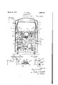
Flg. 1 shows the invention in central vert1cal section. I Flg. 2 is a detail of the oscillating drive mechanism, enlarged. v i
Fig. 3 is a plan view of the machine with the tub removed.
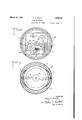
Fig. 4 is a cross-section on the broken line 00 4-4 of Fig. 1.
F1g. 5 is a detail of the water control devices.
The machine is supported on a main frame, consisting of le s 1 and cross-pieces 2, there being supporte on thenpper ends of the legs 3,611'011131 late 3, on which is mounted a track 4., whic is held in an inwardly inclmed position. Operating on the track 4 1s a plurality of rollers 5, attached to the 7 outer face of a tub 6 near the bottom there of. The tub is thereby supported so as to be capable of a free axial rotation. At 0 posite sides of the tub are enlargements forming shallow chambers which communicate with the interior of the tub through perforations 8. The lower parts of said chambers are connected by conduits 9 with a central compartment formed by a casing 10 attached to the lower part of the tub. Said conduits are radially and diametrically opposed to each other, and each is provided with a valve-seat and valve 11 thereon, provided with'stems 12, projecting downwardly beyond the conduit, casings and provided with rollers for operation on a se ental track 13, supported in the frame,-an on the upper face 0 which are cams 14, preferably three in number. By engagement of said cams with the rollers on the valve-stems the valves 11 are opened, the cams being so ositioned that under no circumstances will 7 0th of the valves be actuated at the same time.
' The bottom of the casing 10 communicates through a pipe 15 with a rotary pm 16 operated by an electric motor 17, through which water introduced throughthe pipe 15 is carried and discharged through a pipe 18 to a vertical 'ipe 19, through which the water is carried ack into the tub. On the thereon and rotatable t end of the motor shaft isa pulley 21, con nected by a belt 22 with a pulley 23 on a shaft frame of the machine 24, sup orted in the in ara e1 relation with the motor shaft. Fixed on the shaft 24' is a bevel-gear wheel 25 in mesh with a similar wheel 26 on the lower end of a vertical shaft 27 Fixed to the upper end of said shaft is a gear-wheel 28, in engagement with a similar wheel 29 on a sleeve the upper'end 0 which is a gear-wheel 33, in mesh with a gear-wheel 34 on a sleeve extension 35 of the casing 10. The sleeve 30 can be caused to rotate with the shaft 32 by means of a clutch 36 on said shaft, slidable herewith, said clutch being operable by a lever 37 connected by a rod 38 with a hand-lever 39, fulcr'umed in a casing 40 with which the machine is enclosed. When the clutch 36 is in engagement with the sleeve 30 the movement of the motor shaft will bewimparted through the shafts 24, 27, and 32 and intermediate gearing to the casing 10 and tub 6, to cause a continuous rotation thereof. It Wlll be noted that the conduits 9 and valves therein also receive a rotary movement with the tub, the valves being alternately opened by the engagement of the lower ends 0 the valve stems with the cams 0 on the track 13. When either valve is opened a suctionis formed through the conduit in which it is positioned into the casing 10, down through the pipe 15 and pump 16, and back through the pipes 18 and 19 into the tub. This movement is assisted b the centrifugal action of the tub, tending to orce the water into the chamber 7 which is open to the pump. By having the suctionact alternately on opposite sides of the tub there is less danger of the 0 load becoming packed or held against the sides of the tub, as is frequently the case with centrifugal machines.
If it is desired to have the tub oscillated instead of rotated this may be accomplished by 4 the following mechanism: Supported above the shaft 24 is a worm-gear wheel 42, engaged by a worm 43 on the shaft 24, and on the lower end of the shaft 32 is a sleeve 44, within which the shaft rotates freely. Projecting from the sleeve 44 is an arm 45, connected by a pitman 46 with the wheel 42, the connection between the pitman and arm consisting of a universal joint, and the other end of the pitman being pivoted to a swivel-pin 47 in the wheel 42. The rotation of the wheel 42 is thereby caused to give an oscillating movement to the sleeve 44. By movement downwardly the clutch 36 is engageable with the sleeve 44, imparting the movement of said sleeve to the shaft 32,
'00 and through said shaft and the gear- wheels 33 and 34 to the tub 6, (giving thereto a partial rotary movement an return. As aresult each of the valves 11 is operated by one of the end cams 14 and by the middle one, the
o5 movement of the tub being approximately a 30, rotating freel on a vertical shaft 32, on
three-fourths stfevolution in'each direction. To revent too abrupt a shock at the ends of t e oscillations the sleeve 44 is provided withfa'narm 48, connected with the frame of the machine in opposite directions by shockabsorbing springs 49.
The connection between the pipes 18 and 19 consists of a valve casing 50, with which is also connected a T pipe 51, the branch 52 of which may be connected with any suitable source of water supply. At the opposite end of the,pipe 51 is a valve casing 53, connected by a pipe 54 with the vertical pipe 15. When the valve in the casing 53, under the control of a lever 55, is opened, the water is permitted to pass through the pipe 54 into the pipe 15, and thence into thepump 16, from whic it is forced back through the pipe 18 and valve at 50 which is normally open for communication between the pipes 18 and 19 into the pipe 19, and thence into the tub. When the tub has been provided with a sufficient supply of water the valve at 55 is closed, and the continued action of the pump will cause the water to circulate in the machine, as hereinbefore mentioned. If it is desired to drain the water from the tub the valve in the casing 50 is operated by means of a lever 56, openlng a passage to the pipe 51, and at the same time closing the passage to the pipe 19. The water will then pass outwardly through the pipes 51 and 52.
At 57 is indicated an electric heater of any approved construction through which the water passes from the pump on its way to the tub. After the tub is first filled the water can be circulated through the pipes and pump and back into the tub until it is sufficiently heated, and this heat can be retained during the washing operation by keeping the heater going all or a part of the time, as may be necessary. As hereinbefore mentioned, after the loadof clothes has been suflic-iently washed in the hot water, the water can be drained off, and a fresh su ply provided, for bluing or rinsing the clot es, or other purposes, and the water changed as often as may be desired. After the water has been drained off for the last time the tub is a ain operated with the load, the centrifugal orce driving the remainder of the water out of the clothes, the water being permitted to escape through the chambers 7, first at one side of the tub and then at the other.
It will be observed that whether the tub is being rotated or oscillated the action of the machine will be the same, the alternating suctions of the water through the chambers at the sides of the tub being of a pulsatory character, and following each other in more or less rapid succession, depending upon the regulation of the speed by the varying sizes of the gears in the driving mechanism, or other speed control.
It will be obvious that when the clutch 36 is in a neutral positionno movement will be imparted to the tub, that when the clutch is connected with the sleeve 30 a rotary movement will ensue, and that the engagement of the clutch with the sleeve 44 will result in the oscillation of the tub. I
The machine is preferably formed of metal throughout, and various changes and adaptations thereof can be made without departin from the scope of the invention, as set fort herein.
What I claim, and desire to secure by Letters Patent, is:
1. A washing machine, comprising a frame, a tub rotatably supported therein, chambers at the sides of said tub having openings in communication therewith, a central chamber and conduits between the same and said side chambers, said central chamber and conduits being rotatable with the tub, valves in said conduits holding the same normall closed, means for successive operation of sald valves by the rotation of the tub, and a ipe system connected with said central cham er, including means for drawing the water from the tub through said central chamber and returning the same to the tub with a pulsatory action.
2. In a washing machine, a frame, a tub rotatably and oscillatably mounted therein, a pair of chambers at the side of the tub having openings, in communication therewith, a central suction chamber beneath the tub, conduits connecting said central chamber with the side chambers, valves in said passages normally closed, said chambers and conduits being connected with the tub to rotate therewith, means in said frame for opening said valves alternately upon a rotary or oscillating movement of the tub, and a water system connected with said central chamber and including a force mechanism for drawing water from the tub through said chamber and conduits with a pulsatory action and returning it thereto.
In testimony whereof I aflix my signature.
- TROY A. RIALL.
Priority Applications (1)
| Application Number | Priority Date | Filing Date | Title |
|---|---|---|---|
| US302404A US1850138A (en) | 1928-08-27 | 1928-08-27 | Washing machine |
Applications Claiming Priority (1)
| Application Number | Priority Date | Filing Date | Title |
|---|---|---|---|
| US302404A US1850138A (en) | 1928-08-27 | 1928-08-27 | Washing machine |
Publications (1)
| Publication Number | Publication Date |
|---|---|
| US1850138A true US1850138A (en) | 1932-03-22 |
Family
ID=23167605
Family Applications (1)
| Application Number | Title | Priority Date | Filing Date |
|---|---|---|---|
| US302404A Expired - Lifetime US1850138A (en) | 1928-08-27 | 1928-08-27 | Washing machine |
Country Status (1)
| Country | Link |
|---|---|
| US (1) | US1850138A (en) |
Cited By (13)
| Publication number | Priority date | Publication date | Assignee | Title |
|---|---|---|---|---|
| DE742793C (en) * | 1937-06-20 | 1943-12-11 | Fritz Frhr Von Wieser Dipl Ing | Single drum washing machine for washing and spinning |
| US2446989A (en) * | 1945-04-27 | 1948-08-10 | Peres G Polhemus | Automatic heat controlled apparatus for preparing pads |
| US2554229A (en) * | 1947-02-24 | 1951-05-22 | Gen Electric | Spin basket and casing for clotheswashing machines |
| US2589247A (en) * | 1949-07-06 | 1952-03-18 | Guzzetti Alfredo | Pump operated recirculation washing machine |
| US2603005A (en) * | 1950-06-10 | 1952-07-15 | Perry T Ford | Apparatus for venting the interior of rotary driers and mixers |
| US2630001A (en) * | 1948-08-20 | 1953-03-03 | Bush Ag | Washing machine |
| US2718772A (en) * | 1952-11-07 | 1955-09-27 | Gen Electric | Sediment ejection |
| US2846037A (en) * | 1954-11-02 | 1958-08-05 | Fletcher Works Inc | Drive and control mechanism for washer-extractors |
| US2872801A (en) * | 1953-10-05 | 1959-02-10 | Maytag Co | Single rotary tub construction for washing machines |
| US3062031A (en) * | 1959-05-30 | 1962-11-06 | Balik Franz | Washing and hydroextracting machine |
| US6233982B1 (en) * | 1995-04-13 | 2001-05-22 | Thies Ag | Method and device for the treatment of ready-to-wear, textile apparel parts |
| US20040168482A1 (en) * | 1998-08-18 | 2004-09-02 | Lg Electronics, Inc. | Penetration type washing machine, method for controlling the same, and tub cover for the same |
| US20050011233A1 (en) * | 2002-08-27 | 2005-01-20 | Raveendran Vaidhyanathan | Drive mechanism for an automatic washer |
-
1928
- 1928-08-27 US US302404A patent/US1850138A/en not_active Expired - Lifetime
Cited By (16)
| Publication number | Priority date | Publication date | Assignee | Title |
|---|---|---|---|---|
| DE742793C (en) * | 1937-06-20 | 1943-12-11 | Fritz Frhr Von Wieser Dipl Ing | Single drum washing machine for washing and spinning |
| US2446989A (en) * | 1945-04-27 | 1948-08-10 | Peres G Polhemus | Automatic heat controlled apparatus for preparing pads |
| US2554229A (en) * | 1947-02-24 | 1951-05-22 | Gen Electric | Spin basket and casing for clotheswashing machines |
| US2630001A (en) * | 1948-08-20 | 1953-03-03 | Bush Ag | Washing machine |
| US2589247A (en) * | 1949-07-06 | 1952-03-18 | Guzzetti Alfredo | Pump operated recirculation washing machine |
| US2603005A (en) * | 1950-06-10 | 1952-07-15 | Perry T Ford | Apparatus for venting the interior of rotary driers and mixers |
| US2718772A (en) * | 1952-11-07 | 1955-09-27 | Gen Electric | Sediment ejection |
| US2872801A (en) * | 1953-10-05 | 1959-02-10 | Maytag Co | Single rotary tub construction for washing machines |
| US2846037A (en) * | 1954-11-02 | 1958-08-05 | Fletcher Works Inc | Drive and control mechanism for washer-extractors |
| US3062031A (en) * | 1959-05-30 | 1962-11-06 | Balik Franz | Washing and hydroextracting machine |
| US6233982B1 (en) * | 1995-04-13 | 2001-05-22 | Thies Ag | Method and device for the treatment of ready-to-wear, textile apparel parts |
| US20040168482A1 (en) * | 1998-08-18 | 2004-09-02 | Lg Electronics, Inc. | Penetration type washing machine, method for controlling the same, and tub cover for the same |
| US7263862B2 (en) * | 1998-08-18 | 2007-09-04 | Lg Electronics, Inc. | Penetration type washing machine, method for controlling the same, and tub cover |
| US7263864B2 (en) | 1998-08-18 | 2007-09-04 | Lg Electronics Inc. | Penetration type washing machine, method for controlling the same, and tub cover for the same |
| US20050011233A1 (en) * | 2002-08-27 | 2005-01-20 | Raveendran Vaidhyanathan | Drive mechanism for an automatic washer |
| US7107798B2 (en) * | 2002-08-27 | 2006-09-19 | Whirlpool Corporation | Drive mechanism for an automatic washer |
Similar Documents
| Publication | Publication Date | Title |
|---|---|---|
| US1850138A (en) | Washing machine | |
| US2265516A (en) | Washing machine | |
| US2807951A (en) | Washing machine drive mechanism | |
| US2706899A (en) | Laundry machines | |
| US2325837A (en) | Domestic appliance | |
| US2264202A (en) | Washing machine | |
| US1501746A (en) | Washing machine | |
| US2369905A (en) | Laundry machine | |
| US2223998A (en) | Laundry apparatus | |
| US2292815A (en) | Washing machine | |
| US1631266A (en) | Washing machine | |
| US2171499A (en) | Dry-cleaning machine | |
| US1696718A (en) | Washing machine | |
| US3285038A (en) | Laundry machines | |
| US2561119A (en) | Automatic laundry machine of the squeezer type | |
| US2227077A (en) | Automatic control mechanism | |
| US1935145A (en) | Washer, spinner, and drier | |
| US2339345A (en) | Laundry machine | |
| US2692494A (en) | Combined agitator and flexible diaphragm for washing machines | |
| US2826055A (en) | Washing machine drive mechanism | |
| US2645916A (en) | Horizontal axis washer and squeezer extractor | |
| US1945477A (en) | Washing machine | |
| US1971980A (en) | Washing machine | |
| US1434595A (en) | Washing machine | |
| US2927450A (en) | Combination washer-dryer |