US1964715A - Strand-manipulating mechanism - Google Patents
Strand-manipulating mechanism Download PDFInfo
- Publication number
- US1964715A US1964715A US508868A US50886831A US1964715A US 1964715 A US1964715 A US 1964715A US 508868 A US508868 A US 508868A US 50886831 A US50886831 A US 50886831A US 1964715 A US1964715 A US 1964715A
- Authority
- US
- United States
- Prior art keywords
- strand
- winding
- machine
- rolls
- carrier
- Prior art date
- Legal status (The legal status is an assumption and is not a legal conclusion. Google has not performed a legal analysis and makes no representation as to the accuracy of the status listed.)
- Expired - Lifetime
Links
Images


Classifications
-
- B—PERFORMING OPERATIONS; TRANSPORTING
- B65—CONVEYING; PACKING; STORING; HANDLING THIN OR FILAMENTARY MATERIAL
- B65H—HANDLING THIN OR FILAMENTARY MATERIAL, e.g. SHEETS, WEBS, CABLES
- B65H54/00—Winding, coiling, or depositing filamentary material
- B65H54/02—Winding and traversing material on to reels, bobbins, tubes, or like package cores or formers
- B65H54/22—Automatic winding machines, i.e. machines with servicing units for automatically performing end-finding, interconnecting of successive lengths of material, controlling and fault-detecting of the running material and replacing or removing of full or empty cores
- B65H54/24—Automatic winding machines, i.e. machines with servicing units for automatically performing end-finding, interconnecting of successive lengths of material, controlling and fault-detecting of the running material and replacing or removing of full or empty cores having a plurality of winding units moving along an endless path past one or more fixed servicing units
-
- B—PERFORMING OPERATIONS; TRANSPORTING
- B65—CONVEYING; PACKING; STORING; HANDLING THIN OR FILAMENTARY MATERIAL
- B65H—HANDLING THIN OR FILAMENTARY MATERIAL, e.g. SHEETS, WEBS, CABLES
- B65H2701/00—Handled material; Storage means
- B65H2701/30—Handled filamentary material
- B65H2701/31—Textiles threads or artificial strands of filaments
Definitions
- a subordinate object is to enable the twisting, drafting or spinning devices to operate during such circulatory;
- a further object of the invention is to provide for automatically effecting the stopping or starting, or both the stopping and starting, of the drafting, twisting or spinning devices at one or more predetermined points in the circulatory path of the devices for presenting the devices to an operator or to an automatic mechanism in convenient state for dofling, donning or other replenishment or supervisory operations.
- Another object of the invention is to provide an improved textile machine capable of spinning or twisting a strand and producing in a single winding operation concomitantly with the spinning or twisting, a traverse-wound headless selfsustaining package or cheese constituted of overlapped layers of reversed quick-pitch spiral windmgs.
- Another object of the invention is to provide improved organizations of driving and strand manipulating devices-in textile and like machines having a multiplicity of strand-manipulating devices capable of circulatory travel.
- the high-speed driven element or elements of the units of circulatory spin-e ningortwistingmachines,orthewindinginstrumentalities of the units of a circulatory winding machine are enabled by this invention to be driven, if desired, at rates independent of or different from each other, by a motor traveling with In the case of the unit in its circulatory path. all of these machines such improvement obviates the necessity of reliance upon adaptations of mechanical driving connections unsuited to the transmission of high-speed motion to circulating units.
- My Letters Patent No. 1,609,639, December 10, 1920 discloses winding carriers driven by elongated tractor rolls extending along the guideway of a circulatory winding machine for the rewinding of a large number of yarn supply packages which may be circulated about the machine. Construction and maintenance of the patented mechanism is necessarily accurate and therefore expensive; otherwise defects of operation become limiting factors in the production of machines having 'more than a. certain speed or vmore than a certain length. 0n the other hand ment of driving connections operated in different ways at different speeds.
- My invention further provides competent mechanism for feeding one or more strands to a strandmanipulating or strand-using device capable of circulatory travel, and such mechanism may, and in some cases preferably does, include instrumentalitiescapable of drawing or elongating the strand'preparatory to delivering it to the other strand-manipulating or strand-using device.
- the drawing devices and the spinning, twisting or devices are not necessarily dependent upon each other or upon a common drive device for their motions.
- the strand-drafting or feeding mechanism for example may be operated from one source, preferably an electric motor, movable with the drafting or feeding mechanism; whereas, the spinning, twisting or winding devices are operated from another source; in cases where the strand is drawn out or fed at a relatively slow rate, for example tageously be operated by non-circulating methe drafting or feeding mechanism may advanchanical connections such for example as the tractor rolls referred to above, and the spinning, twisting or winding devices may then be operated independently, for example by an electric motor.
- a further object of the invention is to provide for the control of drive motors of traveling textile devices to effect stoppage of the motors severally upon the occurrence of abnormal conditions in the several strands being wound, unwound, twisted, spun, or drafted by the motors, such abnormal conditions including exhaustion or breakage of the strand or the presence of an imperfection, for example, a slab, therein.
- Another object of the invention is to provide for controlling the individual motors of such a machine severally by the sizes of the strand packages wound or unwound by the operation of the motors.
- a further object is to provide for automatlcally restarting the motors of successive circulatory units following stoppage caused by the occurrence of abnormal conditions of the strands or by the attainment by the packages of predetermined sizes.
- Another object of the invention to provide improved driving connections for quick-traverse devices ofthe kind suitable to wind traverse wound cheeses or Fiji packages during traveling motion in a machine, and to provide for the several control of the many traverse'devices of such a machine by turning on and of! motors .while permitting the traverse devices during their periods of inaction to be connected to their driving motors.
- My invention has for another of its objects to provide a novel form of spinning, twisting or drafting machine constituted of a plurality of individual interchangeable units independently supported by a main frame or guideway and individually removable therefrom without preventing operation of the other units of the machine.
- Fur-' ther objects of my invention are to provide improved driving connections and improved detector and controlling devices applicableto strandmanipulating machines generally and particular- I ly to strand-manipulating machines built according to the unit construction. exemplified by the devices disclosed in this specification.
- a further object of the invention is to provide if desired for the operation in synchronism of many of the corresponding parts of the several units of which the machineis constituted.
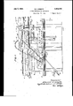
- - Fig. 1 is a side elevation (with certain parts broken away) of one end of a framework defining a circulatory path of travel for the circulatory unit carriers of the machine, and equipped with driving connections suitable for the unit carriers of Figures 5, 6 and 7; Figs. 8, 9 and 10, Figs. 14, and 15, and Figs. 16, 17 and 18, the structure of Fig. 1 being suitable uponthe removal of cer- 11 tain elements to operate in conjunction with the unit carriers of Figs. 11, 12 and 13, Figs. 19 and 20, and Figs. 22 and 23;
- Fig.2 is a section on the line 22 of Fig. 1;
- Fig. 3 is a plan view of the structure of Fig. 1;
- Fig. 4 is a fragmentary view showing in plan a typical arrangement of connections for holding and moving the unit carriers in relation to the guideway of the machine; r
- Fig. 5 is a vertical section taken for example on the line a:a: of Fig. 1, illustrating a twister and its carrier in operative position in the ma chine;
- Fig. 6 is a horizontal section on the line 66 Of Fig. 5; 125 Fig. '7 is a side elevation of the mechanism of Fig. 5;
- Fig. 8 is a vertical section similar to Fig. 5, illustrating a carrier having spinning mechanism thereon, this mechanism including many elements of the mechanism of Figs. 5, 6 and 7 and in addition thereto a strand-drafting device;
- Fig. 9 is a side elevation of the drafting mechanism of Fig. 8, taken on the line 99 of Fig. 8;
- Fig. 10 is a fragmentary side elevation of parts of the twisting and winding instrumentalities of the mechanism of Fig. 8;
- Fig. 11 is a vertical section similar to Figs. 5 and 8, illustrating a similar unit carrier having spining mechanism thereon, this mechanism including many of the features of the mechanism of Figs. 5 to 10, but being capable of operating without the tractor rolls of the machine, such tractor rolls being omitted in this view;
- Fig. 12 is a side elevation of the mechanism of Fi 11;
- FIG. 12 is a fragmentary elevation of certain gearing in the drafting head of the device of Figs. 11, 12 and 13, this view being taken at right angles to Fig. 12 and directly opposite to Fig. 11; 150
- Fig. 13 is a horizbntal section on the line 13-13 of Fig. 11;
- Fig. 14 is a vertical section similar to Figs, 5.
- FIG. 14a is a' fragmentary view of the stopmotion mechanism of Fig. 14 in its normal or running position;
- FIG. 14 is a side elevation of the mechanism of Fig. 14;
- Fig. 15 is a u u tic side elevation of parts of a controlling device for certain forms of the illustrated traveling units;
- Fig. 15' is a fragmentary viewlike Fig. 15 showing a part of the stop-motion device in the act of being operated;
- Fig. 16 is a verticalsection similar to Figs. 5, 8, 1'1 and 14, illustrating another form of spinning mechanism and its carrier in operative position in the machine, this mechanism including many of the features of the mechanism of Figs. 14 and 15;
- Fig. 1'! is a horizontal section on the line 1'l17 of Fig. 16; v
- Fig. 18 is a side elevation of the mechanism of Figs.16and1'7:'
- Fig. 19 includes a fragmentary vertical section illustrating the traverse guide of the devices of Figs. 14, 15, 16, and 18, and the cam follower by means of which the guide is traversed, and includes "also a fragmentary plan view of this traverse guide;
- strand-manipulating mechaall of the illustrated forms of mechanism include instrumentalities capable of eifecting a winding operation, and instrumentalities capable of distributing the winding strand on a receiver such as a spool, core or bobbin, to form a wound package, the mechanisms of Figs. 14 and 15, Figs. 16, 1'1 and 18, including instrumentalities capable of a strand on a receiver or package by overlapped layers of reversed spiral windings, thus to form'a headless self-sustaining strand package.
- Figs. 16, 17 and 18 include instrumentalities effective to unwind a supply strand mass and feed thestrand to strand-manipulating or strand-using mech.
- the forms of mechanism of Figs. 8, 9 and 10, Figs. 11, 12 and 13, and Figs. 16, 1'7 and 18 include instrumentalities effective to draft one or more strands, these drafting in strumentalities herein (although not necessarily) perfo strand unwinding and. delivery functions.
- Figs. 16, 17 and 18 include instrumentalities eifective to impart a twist to, or to twist together, one or more strands, while the forms of -mechanism of Figs. 8, 3 and 10 and Figs. 16, l? and 18 include combinations of instrumentalities, efiective to spin one or more strands.
- the twisting during winding takes place as a consequence of the relative motion between a twisting guide and the supply and receiving packages; in the forms of mechanism of Figs. 14 and 15, and.
- Figs. 16, 17 and 18 the twisting takes place as a consequence of a rotation of the unwinding supply mass or masses with respect ing package.
- the forms of mechanism of Figs. 5, 6 and 7, Figs. 14 and 15, and Figs. 16. 17 and 18 include instrumentalities eifective to stop operation of the winding instrumentalities of the mechanism upon the occurrence of an abnormal condition in the strand under manipulation, the stopmotion instrumentalities of the forms of mechanism of Figs. 5, 6 and '7, and Figs. 14, and 15,
- a machine according to the present invention includes a guideway, herein shown as constituted of upper and lower rails 4 and 5, defining a path of circulation for a plurality of unit carriers of strand-manipulating devices.
- a preferable frame for the machine includes spaced transversely disposed castings l braced by opposite longitudinally extending portions of the rails 4 and5 secured thereto, and longitudinally disposed end castings 2 each secured to, an end transverse casting 1 and braced by semicircular end portions of the rails 4 and 5.
- Figs. 1 and 3 show only one end of the frame and guideway of the present machine; the opposite end of the frame and guideway preferably being substantially the same, 'so that a closed path of circulation is provided.
- Means is provided for moving the carriers in a procession about the machine, such motion being continued or intermittent, and in one direction or alternatively in opposite directions.
- this means is particularly adapted for continued motion, of the carriers-(interrupted as desired) in a single direction, about the machine.
- Such means is shown by way of example as including a chain 1 generally parallel to the closed path defined by the upper rail 4, moving on sprocket wheels 8, of which the one shown is driven through a worm gear 10, worm ll, shaft 13-. pulley 14, belt 16 and pulley 17 from an electric motor 19 or other source of power.
- Means is also provided for operating 'a plurality of motors (usually of high speed) which furnish power for the manipulation of strands on the various movable units.
- the motors are shown as being electric motors; accordingly the operating connections thereto include electrical conductors leading to these motors from a sourceof electrical energy.
- electrical conductors take the form of rails 40, 41 and 42 disposed to furnish three-phase current to the several carriers in various positions of the carriers, whether moving or stationary.
- these rails are vertically superposed, and are secured'to and suitably insulated from the frame or stationary portion of the machine.
- the length of these .rails may be determined by the extent of portions of the guideway on which it is desired that the yampath of circulation are reached.
- in-' manipulating devices of the carriers be energized.
- the end portions 40, 41 and 42 (mainly semi-circular in outline) of the rails are preferably electrically discontinuous from the main or straight portions'of these rails.
- the end portions 40, 41* and 42 of the conductor rails may be deenergized, thus to stop and start the electrically driven instrumentalities on the carriers successively as predetermined parts of the stances, the end portions 40, 41 and 42 at one or both ends of the machine may be energized by connecting them in parallel with the main portions of the rails 40, 41 and 42, conveniently by means of switches, the switch for this purpose at the illustrated end of the machine being diagrammatically shown at 45. 1
- the circulatory carriers adapted to be used on this machine, it is convenient to provide for receiving the electric current from rails near the upper part of the carrier; in other of the carriers, the electric current is more conveniently received near the lower end of the carrier.
- 3 is shown as'having two duplicate sets of conductor rails so that either of the two sets may be used, as is expedient, or either of the two sets may be dispensed with if only carriers which receive their electric current at the same level are utilized.
- R0- tationof the tractor rolls may be induced by a cross-shaft 20 acting through bevel gearing within the end housings 52, the cross shaft being rotated at an appropriate speed by the motor 19 through a driving pulley 22, belt 23 and'a pulley 25 on the shaft 20.
- the speed of the tractor rolls may be regulated by the provision of suitable gearing, change speed devices, or by the mere substitution for the driving pulley 22 and pulley 25of other pulleys having a different ratio of diameters.
- the tractor rolls 50 and 51 and their bearings and driving connections may be removed from the machine or dispensed with to provide room for the passage of carriers with which these elements are not utilized.
- Certain of the unit carriers of the present machines include, as hereinafter more fully described, a device capable of effecting a relative motion of a spinning or twisting strand and of a strand package being built up therefrom, such as to distribute the spun or twisted strand evenly in building up the strand package.
- a device capable of effecting a relative motion of a spinning or twisting strand and of a strand package being built up therefrom, such as to distribute the spun or twisted strand evenly in building up the strand package.
- an oscillating shaft'70 may be provided longitudinally of the machine, this shaft having at intervals thereon sprockets 71 adapted as the shaft oscillates to wind up and unwind parts of chains '72 and 73 running over pulleys '12"v and 73' and.
- the longitudinal shaft 70 may conveniently be caused to oscillate by the provision thereon of a drum '75 to which is attached and on which runs a chain 76 connected to a, lever 77 which is pivoted to the frame at 78 and carries a cam follower 79.
- a cam 80 driven through gear wheels 81 and 82 from a cross-shaft 83 is adapted to oscillate the lever '17 and hence the shaft 70 and connected lifter rail '60.;
- the cross-shaft '83 may conveniently be driven through a pulley 84, belt 85 and pulley 86 from the motor 19, (Fig.3)
- the above described lifter rail need not be used in connection with certain of the circulatory carriers about to be described, and may in those cases be disconnected from the motor 19..
- the machine Pref-- erably the energization of the conductor rails 40, 41 and 42 is simultaneously controlled by this same switch.
- the machine preferably'includes a belt-shifter 91 con- .trolled by foot pedals 92 and adapted to shift the belt 16 from the pulley 14 to a loose pulley 15 and vice versa.
- the general construction of the machine is preferably such that the numerous strand-manipulating units of the machine, each including a unit frame, are independently supported by the main frame of the machine, are readily removable therefrom, and are interchangeable.
- the various units, intended for use in cooperation with frame, guideway and driving parts such as described, may be individually constructed, the various parts of the unit being aflixed thereto, and the unit being tested and adjusted before assembly of the several units on the guideway. 01' the machine. In this way accuracy of manufacture and standardization of the units of the machine may be assured.
- the independent support of the various units by the main frame of the machine insures that the relations of the various parts of a given spinning, twisting or drafting unit will not be afiected by slight distortion of the long main frame and guideway structural elements.
- the main frame of the machine may be relatively light considering the fact that the 7 units may continually move around the frame,
- the individual spinning, and drafting units of the machine depending for proper alignclosed path, the individual units of the machinev being adapted to be articulated for passage about curved portions of the guideway.
- the carriers or units of the variousmachines preferably include an upright unit frame portion the distance between the upper and lower guide rails 4 and 5, and having in association therewith a pair of anti-frictionrolls 101, 101 adapted to run on the upper rail 4 and to support the carrier therefrom.
- the lower end of the frame is preferably provided with vertical depending studs 92, 93 on opposite sides of the vertical flange of rail 5, one or both of these studs preferably carrying 'an antifriction roller 94 adapted to run on a face of the vertical flange of rail 5.
- Theheadportionofthe unitframe ofthecarrier is preferably arranged to have limited mo tion with respect to and to be yieldinglvurged toward the upper rail 4, a typical preferred construction for this purpose being shownin Fig. 4.
- Link103 is provided with a lug into which is hooked a tractor rod 105 extending through a bore 106 in the head portion of the carrier and provided with a spring 107 adjustable by a nut 108.
- the spring 107 yieldingly urges the roll 104 toward the head of the carrier and against the inner face of the rail 4. Inward motion of the head portion of the carrier thus induced may by contact of some driven pm of the strand-manipulating-devices of the carrier with a tractor roll 50 or 51, such part of the strand-manipulating device being thus held in frictional contact with the tractor roll, to be driven thereby.
- orinthecaseofthemachinesofl 'igs. 1 1, 12 and 13 wherein the tractor rolls are elima pair of anti-friction rolls 109 are providedonthecarrierinpositiontobealfagainst theouterfaceofrail4insuchcasetooppose the action of spring 107.
- alug 110 isprovidedon therearofthehmdportionofthecarrienhavmg pivotally molmted thereon atractor link 111 which isinturnpivotallyoonnectedtoa lateralextension1l2ofoneofthelinksofchain30.
- thistractorlinklll fromits assol12,asbyremovingasuitable r gidity of the mainpivotpinorthelike,the1mitconstitutedofthe carrier frame and the strand-manipulating devices thereonmaybeliftedtromtheguideway andmainframeofthemachine. Thismavbe accomplished without disturbing any of the numerous other similar strand-manipulating units 'Of the machine 01'- their driving connections, as
- each carrier has mounted thereonthree brushes 114, 115 and 116, disposed either to slide along the respective conductor rails of theupper set as in the devices ofFigs. 5, GandLandEigs. 8, 9,and10,or along the respective conductor rails of the lower set as in the devices of Figs. 11, 12 and 13, Figs. 14 and 15, and Figs. 16,17 and 18.
- Each oftheunitsorcarriers is alsoshownas provided with an electric drive motor M (preferably of the 3-phase type) adapted to operate some or all of the strand-manipulating instrumentaliiies of the unit, and operable by current received from the above conductor rails and, brushes.
- an electric drive motor M preferably of the 3-phase type
- the circulatory strmld-manimlating devices Referring to Figs. 5, 6 and 7, the strand-manipulating mechanism illustrated therein is intended for twisting and rewinding one or more textile strands.
- An upward and inward extending arm forming a-portion of the frame of the carrier is shown as provided with means for holding one or more single or multiple wound supply strand packages S, this holding means-for example taking the form of a pin or pins 121 suitable to retain a cop, bobbin, core, tube, or other wound strand mas.
- One or more suitable strand guides 129 are preferably provided to guide the moving strand or strandsbetweenthesupplypackage S and the MountedontheunitorcarrienIm-ovidemotordrivenmeansforwindingandtwistingthe strand or strands thus delivered, such means preferablyinthisinstancebeingofthatclasof deviceswhichoperatebywindingthestrandor strandsonoverthe'endofasuiuablyrotating strandreeeiver'suchasabobbinorthelikeand comprising essentiallyastrandguideandarotating strand receiver.
- the cap of a cap-spinning or twisting machine the flyer of a fly spinning or twisting machine, or the ringtraveler of a ring spinning machine together with r the strand-receiving bobbins with which these strand-guiding elements cooperate.
- the strand under manipulation frictionally engages the strand-guiding element and winds on the strand-receiving element; a driving force applied to'one of these elements may suiiice to effect the rotary travel of both.
- the angular velocities of these elements differ sufficiently (for example because of greater frictional drag" encountered by one of these elements), to provide an adequate linear rate of winding, while the angular velocity of the strand about a circuitous path defined by the guide is suiiicient to apply a substantial twist to the length a of strand running thereto from the supply.
- a strand receiver in the form of a bobbin 131 is shown as arranged to be rapidly rotated on a suitable spindle 130 by an electric motor M, the strand or strands winding upon the bobbin passingthrough and being guided by a traveler 132 on a spinning ring 133.
- the motor M may conveniently be mounted on a horizontal the conductor rails 40, 41 and 42 while the carrier is either moving or stationary.
- Such means for eflecting a relative traversing motion of the strand-receiving bobbin 131 or the like with respect to the strand-guiding traveler 132.
- such means includes a slide 135 vertically movable on the vertical member 100 of the carrier, the slide having as a lateral extension thereon a ring rail 136 which carries a ring'133 having the traveler 132, the slide having thereon an anti-friction roller follower element 137 adapted to extend into the U-shaped lifter rail 60.
- Detector and controlling devices Preferably means is provided for stopping the operation of the feeding rolls 122 and 123, and for cutting off the supply of current to motor M, or
- an abnormal condition may be a condition of the strand which may be detected by a suitable detector, some instances being exhaustion or breakage of the strand, excessive tension or slack in the strand, or objectionable imperfections in the strand.
- the part of this specification headed "Other detector and controlling devices" deals with means for detecting certain of such abnormal conditions of the strand and means for detecting such conditions.
- the abnormal conditions in the strand as a consequence of which the feed rolls and motor may be stopped are lack of suiiicient tension in the strand, or exhaustion or breakage of the strand.
- the strand in passing from the delivery roll 122 to the traveler 132 preferably passes through a pot-eye 280 which is carried by a lever 281 in position to define a projecting angle in the main path of the strand, the normal tension of the strand thus tending to hold this lever 281 in the illustrated horizontal position, against any suitable stop not shown.
- the opposite end of lever 281 is connected by a link 282 to a horizontal rod 283 (Fig. 7) joined at its ends to spaced lower levers 284 and 285, this arrangement being such that the levers 284 and 285 are normally held in the inclined positions shown.
- Each of these levers carries in a bifurcation at its end an antifriction roll 287, these rolls being slightly inclined downwardly in the direction of motion of the carrier with respect to the rail 4.
- a cam-rail 289 is mounted on the outer vertical face of rail 4 at a level such as normally to clear the'rolls 287, a cam-rail 289 is provided having the upper portion 289' -of its lateral face inclined upward and away from the rolls 287.
- the lower portion 289" of the lateral face of the cam-rail may be vertical, and is preferably of a width to afford a path for rolls 287.
- This cutward motion of the upper portion of the carrier disengages'the cork tire 125 of the lower delivery roll from the tractor roll 50 or 51, and also disengages the brushes 114, 115 and 116 from the conductor rails 40, 41 and-42, stopping both feeding, twisting and winding of the strand.
- a plurality of draft rolls are employed as in the form of mechanism of Figs. 8, 9 and 10, these draft rolls may likewise be stopped.
- the cam rail 289 is in'two sections each approximately coextensive in length with a tractor roll 50 or 51, the cam rail not being needed at the semi-circular ends of the machine.
- the cam Preferably as shown in Fig. 1 the cam.
- the two spindles 130 being herein shown as driven from separate motors M, and the two rings 133 being carried on a common ring rail 136 operated by the previously described builder motion.
- a suitable strand drafting device mounted on the carrier and adapted to cooperate with the twisting and winding instrumentalities to produce a spun strand from roving or the like.
- a strand drafting devise includes a set of lower draft rolls 122 122*, 122 and 122 journaled in spaced inclined extensions 120 of the head of the carrier, and a set of upper rolls 123 123 123 and 123 adapted to press against strands passing over the lower set of draft rolls.
- the intermediate upper rolls 123 and 123 have their journals received in opposite slotted projections 142 and 143.
- the shaft 145 which is fast to and turns with the lower front roll 122*, may carry opposite tractor wheels 145 of enlarged portions carrying tires adapted to contact with the tractor roll 50 or 51, thus effecting rotation of the front lower roll 122
- Shaft 145 preferably also carries, fast thereon, a sprocket wheel 146.
- Similar sprocket wheels 147,- 148, and 149 respectively are associated in like manner with the remaining lower draft rolls, these sprocket wheels being of requisite diameters to cause the lower draft rolls to turn at progressively increased surface speeds as the sprocket wheels are driven by a common chain 150 actuated by the sprocket wheel 146.
- An idler roll 151 having its journal adjustably retained in a slot 152, may serve to take up slack of the chain 150, for example to allow for substitution for sprocket wheels 146, 147, 148, and 149 of similar wheels of various sizes.
- the device of Figs. 8, 9 and 10 is shown as equipped with a pair of pins 121 suitable to receive supplies 5 of strands to be drafted, spun or twisted, and suitable guides 129 for guiding the strands, to the draft rolls.
- a drafting device as the primary strand-manipulating device of the carrier, if desired in association with any form of device to wind up, further manipulate, or use the drafted strands.
- the motor-M is shown as mounted on the lower face of a hollow bracket 360, which receives within it a gear wheel 361 driven by the shaft of the motor.
- Gear wheel 361 meshes 'with each of two smaller gear wheels 362 and 363 respectively fast on spindles 364 and 365 which are mounted in suitable bolsters 366 and 367.
- Each of the spindles 364 and 365 is suitable-to receive a core, tube, bobbin or other receiver for a winding strand mass.
- the device of Figs. 11, 12, and 13 may be provided with strand-drafting mechanism in the form of a lower set of forward, intermediate and rear draft rolls 122 122 122 having their journals received in bearings in spaced extensions 120 of the head of the carrier, and an upper setof forward, intermediate and rear draft rolls 123 123 and 123 having their journals slidably mounted in slots in a frame 3'70 which is pivotally mounted at 371 to the extensions 122cm.
- the lower set of rolls is preferably driven from the motor M by the provision of a vertical shaft 372 mounted in bearings 3'73, 374 and 3'75 in brackets 360, 155, and upper head portion of the carrier respectively, this shaft being suitably connected at its lower end to the shaft of motor M, and being connected to drive the draft rolls from its upper end.
- the upper end of shaft 372 carries at its upper end a worm gear 376 meshing with a gear wheel 37'? (Fig. 12) fast on the forward lower draft roll 122.
- This draft roll also carries a gear. wheel 378, (Fig. 12 meshing with an idler gear 3'79 which carries a pinion 380.
- Pinion 380 in turn meshes with a gear wheel 381 fast on the shaft of intermediate roll 122.
- Rear roll 122 is driven from intermediate roll 122 by gear wheels 384, 385 fast to these respective rolls, and meshing with a suitable id r gear 386, as shown in Fig. 11.
- the ratios of the various gear wheels described above- is such that ill the lower intermediate roll is driven at a greater Figs. 11, 12 and 13, will be obvious from the previous explanation of analogous mechanism. In the operation of this device which relies only upon motor M for the power for its drafting.
- the unit may be operated continuously about the complete circuit of the guideway of Figs. 1, 2 and 3, including the curved end portionsthereof.
- the switches 45 at each end of the machine may be thrown to energize the semi-circular end sectio 40 41 and 42 of the conductor rails, or ifdesired the end sections at only one end (for instance the operators end of the machine) may be deenergized so that the carrier as it traverses this section is inactive, for greater ease of replenishment and supervision.
- the traveling unit of Figs. 14 and 15 is suited primarily to efi'ect a twisting operation on one or more strands by a relative motion of the supply package with respect to the winding strand.
- the device preferably includes the electric motor M, and bolster B of the devices of Figs. 5 to 10.
- the motor driven spindle, indicated in Figs. 14 and 15 by the-reference character 370, is in this instance particularly adapted to receive and rotate the core of an unwinding supply package.
- the motor M may for example rotate a supply package S mounted on the spingether, the unit may includesimilar means for rotating additional supply packages each having one or more strands thereon.
- the unit or carrier includes suitable means for drawing off the strand or strands from the rotating supply package or packages and for winding the twisted rewinding supply package for confining 'the traversing motion of the strand to that portion thereof adjacent to the winding package while preventing the traversing motion from disturbing the whirling balloon effect set up by unwinding from the rapidly rotating unwinding supply package.
- Such guide is herein shown as an eye 371 carried by a cover plate 510 on the head of the carrier.
- the mechanism for drawing off the strand from the supply or supplies and for winding the resultant twisted strand may be similar to the winding mechanism described in my copending application Serial No. 476,776, filed August 21, 1930, entitled Machine and method for preparing yarn packages, and will now be described, by way of example, as thus constructed.
- the upper part or head of the carrier frame may thus include outwardly projecting parallel endplates 566,567 spaced apart to provide room between them for a rotary traverse cam 570 (Figs.
- One of the end plates of the head 65 may be extended as shown at 568 to provide a bearing 569 for a stud 573 on a lever arm 571 carrying a spindle 572 for a winding core or carrier W.
- the length of the lever arm 571 is such that the surface of the winding core W or the winding thereon is in surface contact with one of the tractor rolls 50 or 51 throughout the winding operation.
- the position of the'stud 573 is such as to permit'the used an arm 571 of a length such as to sweep a suilicient are for the expected radius of the carrier W and the winding upon it; In normal operation the weight of the arm 571 and its attachment holds the winding mass firmly in frictional contact with the upper surface of the tractor roll 50 or 51.
- the arm 571 may be made in parts, comprising a tubular portion 571 split at 571 and having lugs bored for a pinch bolt 571, the tubular clamp so formed taking over an end piece 571 carrying the spindle 572.
- the part 571 may be universally adjusted to vary the distancebetween stud 573 and spindle 572, and also to vary the angleof the spindle 572, for example from parallelism with the axis of the roll 50 or 51 to an anglecorresponding to that of a suitable cone carrier for winding a conical package.
- the traverse cam 570 is most clearly shown in Fig. 20.
- the traverse cam 570 is shown as provided with a crossed spiral cam groove 570, preferably of rectangular cross section, and at each end the cam 570 may be provided with a friction ring 570 of cork, cork composition, felt, rubberized felt, rubber aggregated ground cork, or any other durable friction material, said rings projecting slightly beyond the cylindrical surface of the cam body and being frictionally held against one of the tractor rolls 50, 51 by connections explained above 100 (see Fig. 4) which urge the head portion of the carrier toward the rail 4 and roll 50 or 51.
- thehead 65 carries a polished steel bar 500, united at its ends to the plates 566 and 567 respectively .and forming a slideway for a light casting 501 having an opening at 502 for a slide bearing on the bar 500 and provided with a lug 503 bored for a pin 504 having secured to its lower end an arcuate follower 505 engaging the cam groove 570 of the cam 570.
- a yarn guide 506 Integral with the casting 501 is a yarn guide 506 having lateral cam slopes 506 (Fig. 15) and a central yarn notch 506".
- the head 65 is preferably provided with a sheet metal cover plate 510 which includes a substantially flat horizontal portion overhanging bar 500 and having a straight edge parallel to the axis of the motion of the cam 570 and the tractor rolls.
- the cover plate also includes a part which slopes downwardly and outwardly as indicated in Figs. 120 14 and 15, the lower end of this portion carrying the guide eye 371..
- a suitable slub detector, catcher or breaker may conveniently be mounted on the cover plate, such device being shown by way of example as constituted of parallel spaced wide blades 400 and 401 defining a narrow throat 402 for the passage of the strand but not for undesired imperfections thereon, in the manner described in my above mentioned application and in my application Serial No. 484,993, filed September 29, 1930, entitled Slub detector, catcher or breaker.
- this slub catcher is suited to cause breakage of the resultant twisted strand upon the occurrence of an undesired imperfection therein incapable of being removed'by passage through the throat 402 of the slub catcher.
- the slub catcher constituted of blades 400 and 401 is effective to induce breakage'of the strand when a slnb incapable of being removed by the blades is encountered.
- a litter rod 207 connected at its upper end to the pivoted package-carrying am 571 of the head.
- pins 208 are provided for swinging the dog 203, shaft 205 and arm 206 and thereby operating the lifter rod 207 to swing arm .slub, however, the feeler 200 rises, the dog 203 drops to the position of Fig. 14, wherein it can strike and be rotated by a pin 208 as indicated in Fig. 15'.
- Means is preferably provided for controlling the mo or M in accordance with the attained size of the winding package, and such means may include certain of the connections serving to control the switch 216.
- the package-carrying arm 571'"and switch-actuating arm 217 are gradually movedin a clockwise direction by the increase in diameter of the package.
- the switchactuating arm 216 will actuate the switch 215 to turn ofi the current to motor M.
- the device may accurately set to operate the switch upon the attainment by the winding package of any desired size.
- the non-rotation of the unwinding package S serves to indicate to an operator that the carrier is full.
- the means for cutting 011 the power of motor M may be simplified by connecting the feeler 200, or whatever detector it is desired to use, directly to a motor controlling switch.
- the devices for stopping driving of the winding package by moving it away from its tractor roll, and for removing the winding strand from its traverse device may be utilized separately from such means for controlling the motor M, such devices apart from their cooperation with such motor-controlling means being herein illustrated in the forms described and claimed in my above application, Serial No. 476,776.
- the machine may also be capable of cutting off the power of the individual driving motor M, stopping the driving of the winding package and its core W, shifting the position of the winding package to a more convenient position for attention thereto and removing the winding strand from-the traversing mechanism, or any of these functions severally, upon the attainment by the individual carrier of a predetermined part of its circulatory path.
- the parts described above as controlled by the feeler 200 and link 202 for performance of these functions upon the occurrence of abnormal conditions in the winding strand may cooperate with suitable abutments at points on the guideway so as to be actuated when the carrier attains a predetermined part of its path. Referring particularly to Fig.
- the upper rail 4 of the guideway may have thereon at any desired point a pin 219 similar to the previously described pins 208 but long enough to contact with and actuate the dogs203 of the carriers even when the dogs are held out away from the rail by the normal winding of the strands.
- Such pins may be stationed just in advance of the end bearings 52, 53 of the tractor rolls'50, 51 there serving in conjunction with the operative connections on the several carriers to remove the winding package from the tractor rolls 50 and 51 before the end bearings 52 or 53 are reached, and simultaneously to stop the motor M.
- the motors M of the several carriers may also be stopped just before the ends ofthe tractor rolls are reached by virtue of the carrier current brushes of the carrier passing onto deenergized end sections of 40 41 and 42 of the current conductor rails.
- the frame of the machine (Figs. 2 and 3) is shown by way of example as provided with one of the above described pins 219,'at a point on the rail 4 lyin between the ends of the energized straight portions oiconductor rails 40, 41, 42, by means of which pin the above described controlling functions may be performed in respect to the several carriers at a point at which the conductor rails 40, 41, 42 would otherwise cause the motor M to be driven.
Landscapes
- Spinning Or Twisting Of Yarns (AREA)
Description
Filed Jan. 15. 1951 11 Sheets-Sheet 1' I Inventor Edward A *y W z 1/ M it A zls' Attfys;
July 3,1934. E. J. ABBOTT 1,964,715
STRAND MANIPULATING MECHANISM Filed Jan. 15, 1931 11 Sheets-Sheet 2.-
In van for:
E. J. ABBOTT STRAND MANIPULA'IING MECHKNISM Filed Jan. 15, 1951 y 11 s eets-sheets M kw. r
IIIIILII Il Itl Edward v (W v .July 3, 1934. 1 E. J. ABBOTT I STRAND MANIPULATING MECHANISM Filed Jan. 15, 1931 11 Sheets-Shet 4 @2876207 ma? aw. 1
Yen's-aw July 3, 1934. V J. ABBOTT Z I 11,964,715
STRAND MANIPULATING MECiHAlIISLI Filed Jan. 15, 1951 11 Sheets-Sheet 5 July 3, 1934.
E. J. ABBOTT STRAND MANIPULATING MECHANISM Filed Jan. 15, 19:51 I
{fur/enter;
byww
Ms A Zq'ya.
E. J. ABBOTT 1,964,715
S TRAND MANI PULATI NG MECHANI SM July 3, 1934.
11 Sheets-Sheet '1 Filed Jan. 15, 1951 Inventor:
Edward W456 7211's A a};
July 3, 1934. E. J. ABBOTT] STRAND MANIPULATI NG MECHANISM 11 Sheets-Sheet 8 Filed Jan. 15, 1931 1710622107; v Z'ciwgn i M1465? $13 At y;-
E. J. ABBOTT July 3, 1934.
' STRAND MANIBULATING MEE ANISM 1931 11 she ts-sheet 9 Filed Jafi. 15
Flaw
E. J; ABBOTT STRAND MANIPULATING MECHANISM July 3, 1934.
, 1931 ll Sheets-Sheet 10 Filed Jan. 15
izzs .Attys.
fn ventor Z grdJA 0 July 3, 1934.
I E. J. ABBOTT 1,964,715
STRAND MANIPULATING MECHANISM Filed Jan. 15, 1931 11 Sheets-Sheet 11' J72 vemfmf v fi my? JA 2? v /fv Mr J l kz's A Ztys Patented July 3, 1934 UNITED STATES PATENT OFFICE STRAND-MANIPULATIKG MECHANISM Edward J." Abbott, Wilton, N. 11., jlsignur to Abbott Machine Company, Wilton, N. 11., a corporation of NewHam Application January 15, 19:1, Serial No. 508,868
4: Claims. (Cl. 118 31) up of broken ends of yarn or other strand being manipulated. By attaining this object, among others, this invention obviates the necssityof much or all of the usual travel of an attendant,
and transport by her of the supply and resulting strand packages, incident to the customary re-' plenishment and supervision of present twisting, drafting and spinning machines. A subordinate object is to enable the twisting, drafting or spinning devices to operate during such circulatory;
motion, or during intervals between successive steps in such circulatory motion so that some of the circulatory units may be subjected to replenishment, cleaning, and/or other operations effected by an operator or automatic devices stationed at one part of the path of circulation concomitantly with the progress of the operations of drafting, spinning or twisting upon other units.
A further object of the invention is to provide for automatically effecting the stopping or starting, or both the stopping and starting, of the drafting, twisting or spinning devices at one or more predetermined points in the circulatory path of the devices for presenting the devices to an operator or to an automatic mechanism in convenient state for dofling, donning or other replenishment or supervisory operations.
Another object of the invention is to provide an improved textile machine capable of spinning or twisting a strand and producing in a single winding operation concomitantly with the spinning or twisting, a traverse-wound headless selfsustaining package or cheese constituted of overlapped layers of reversed quick-pitch spiral windmgs.
Another object of the invention is to provide improved organizations of driving and strand manipulating devices-in textile and like machines having a multiplicity of strand-manipulating devices capable of circulatory travel. As exemplifying the improvements eifected by this aspect of my invention, the high-speed driven element or elements of the units of circulatory spin-e ningortwistingmachines,orthewindinginstrumentalities of the units of a circulatory winding machine are enabled by this invention to be driven, if desired, at rates independent of or different from each other, by a motor traveling with In the case of the unit in its circulatory path. all of these machines such improvement obviates the necessity of reliance upon adaptations of mechanical driving connections unsuited to the transmission of high-speed motion to circulating units. My Letters Patent No. 1,609,639, December 10, 1920, discloses winding carriers driven by elongated tractor rolls extending along the guideway of a circulatory winding machine for the rewinding of a large number of yarn supply packages which may be circulated about the machine. Construction and maintenance of the patented mechanism is necessarily accurate and therefore expensive; otherwise defects of operation become limiting factors in the production of machines having 'more than a. certain speed or vmore than a certain length. 0n the other hand ment of driving connections operated in different ways at different speeds.
My invention further provides competent mechanism for feeding one or more strands to a strandmanipulating or strand-using device capable of circulatory travel, and such mechanism may, and in some cases preferably does, include instrumentalitiescapable of drawing or elongating the strand'preparatory to delivering it to the other strand-manipulating or strand-using device. According to this invention, the drawing devices and the spinning, twisting or devices are not necessarily dependent upon each other or upon a common drive device for their motions. The strand-drafting or feeding mechanism for example may be operated from one source, preferably an electric motor, movable with the drafting or feeding mechanism; whereas, the spinning, twisting or winding devices are operated from another source; in cases where the strand is drawn out or fed at a relatively slow rate, for example tageously be operated by non-circulating methe drafting or feeding mechanism may advanchanical connections such for example as the tractor rolls referred to above, and the spinning, twisting or winding devices may then be operated independently, for example by an electric motor.
A further object of the invention is to provide for the control of drive motors of traveling textile devices to effect stoppage of the motors severally upon the occurrence of abnormal conditions in the several strands being wound, unwound, twisted, spun, or drafted by the motors, such abnormal conditions including exhaustion or breakage of the strand or the presence of an imperfection, for example, a slab, therein.
Another object of the invention is to provide for controlling the individual motors of such a machine severally by the sizes of the strand packages wound or unwound by the operation of the motors. .A further object is to provide for automatlcally restarting the motors of successive circulatory units following stoppage caused by the occurrence of abnormal conditions of the strands or by the attainment by the packages of predetermined sizes.
Another object culatory textile machine as the units progress about a curved end as well as along the straight sides of a guideway of the machine.
Another object of the invention to provide improved driving connections for quick-traverse devices ofthe kind suitable to wind traverse wound cheeses or Fiji packages during traveling motion in a machine, and to provide for the several control of the many traverse'devices of such a machine by turning on and of! motors .while permitting the traverse devices during their periods of inaction to be connected to their driving motors.
My invention has for another of its objects to provide a novel form of spinning, twisting or drafting machine constituted of a plurality of individual interchangeable units independently supported by a main frame or guideway and individually removable therefrom without preventing operation of the other units of the machine. Fur-' ther objects of my invention are to provide improved driving connections and improved detector and controlling devices applicableto strandmanipulating machines generally and particular- I ly to strand-manipulating machines built according to the unit construction. exemplified by the devices disclosed in this specification.
A further object of the invention is to provide if desired for the operation in synchronism of many of the corresponding parts of the several units of which the machineis constituted.
Other objects of invention, and features of advantage and novelty will be apparent from a consideration of the explanation in this specification and its drawings of typical illustrative embodiments of my invention. V a
For the purpose of adequately explaining the various phases of my invention, typical devices having therein various combinations of novel features are described and illustrated in this specification and its drawings. It will readily be understood by those skilled in the textile art that many features embodied in the specific machines illustrated and described herein are applicable to other commercial-types or classes of strandmanipulating devices. For example, the drafting and strand-delivery devices of the spinning of the invention is to provide for operating strand-manipulating units of a cirmachines illustrated herewith may be utilized for performing a drafting or delivery operation in respect to any suitable strand manipulating or ing package by means of a motor adapted-to travel therewith are claimed in my copending divisional application on Winding machine, Serial No. 677,749, filed June 24, 1933.
For brevity of description, certain of the elements illustrated in certain of the figures of the drawings are herein explained. by reference to. similar elements which are described with particular reference to other figures of the drawings. In general corresponding reference characters are utilized to indicate corresponding parts in the various figures of the drawings, and corresponding parts in the several embodiments of the invention have in many instances been described specifically but once. n
In the drawings:
- Fig. 1 is a side elevation (with certain parts broken away) of one end of a framework defining a circulatory path of travel for the circulatory unit carriers of the machine, and equipped with driving connections suitable for the unit carriers of Figures 5, 6 and 7; Figs. 8, 9 and 10, Figs. 14, and 15, and Figs. 16, 17 and 18, the structure of Fig. 1 being suitable uponthe removal of cer- 11 tain elements to operate in conjunction with the unit carriers of Figs. 11, 12 and 13, Figs. 19 and 20, and Figs. 22 and 23;
Fig.2 is a section on the line 22 of Fig. 1;
Fig. 3 is a plan view of the structure of Fig. 1;
Fig. 4 is a fragmentary view showing in plan a typical arrangement of connections for holding and moving the unit carriers in relation to the guideway of the machine; r
Fig. 5 is a vertical section taken for example on the line a:a: of Fig. 1, illustrating a twister and its carrier in operative position in the ma chine;
Fig. 6 is a horizontal section on the line 66 Of Fig. 5; 125 Fig. '7 is a side elevation of the mechanism of Fig. 5;
Fig. 8 is a vertical section similar to Fig. 5, illustrating a carrier having spinning mechanism thereon, this mechanism including many elements of the mechanism of Figs. 5, 6 and 7 and in addition thereto a strand-drafting device;
Fig. 9 is a side elevation of the drafting mechanism of Fig. 8, taken on the line 99 of Fig. 8;
Fig. 10 is a fragmentary side elevation of parts of the twisting and winding instrumentalities of the mechanism of Fig. 8;
Fig. 11 is a vertical section similar to Figs. 5 and 8, illustrating a similar unit carrier having spining mechanism thereon, this mechanism including many of the features of the mechanism of Figs. 5 to 10, but being capable of operating without the tractor rolls of the machine, such tractor rolls being omitted in this view;
Fig. 12 is a side elevation of the mechanism of Fi 11;
'Fig. 12 is a fragmentary elevation of certain gearing in the drafting head of the device of Figs. 11, 12 and 13, this view being taken at right angles to Fig. 12 and directly opposite to Fig. 11; 150
Fig. 13 is a horizbntal section on the line 13-13 of Fig. 11;
Fig. 14 is a vertical section similar to Figs, 5.
'8 and 11, another form of twister and its carrier in operative position in the machine; 1
14a is a' fragmentary view of the stopmotion mechanism of Fig. 14 in its normal or running position;
-Fig. is a side elevation of the mechanism of Fig. 14;
Fig. 15 is a u u tic side elevation of parts of a controlling device for certain forms of the illustrated traveling units;
Fig. 15' is a fragmentary viewlike Fig. 15 showing a part of the stop-motion device in the act of being operated;
Fig. 16 is a verticalsection similar to Figs. 5, 8, 1'1 and 14, illustrating another form of spinning mechanism and its carrier in operative position in the machine, this mechanism including many of the features of the mechanism of Figs. 14 and 15;
Fig. 1'! is a horizontal section on the line 1'l17 of Fig. 16; v
Fig. 18 is a side elevation of the mechanism of Figs.16and1'7:'
Fig. 19 includes a fragmentary vertical section illustrating the traverse guide of the devices of Figs. 14, 15, 16, and 18, and the cam follower by means of which the guide is traversed, and includes "also a fragmentary plan view of this traverse guide;
As will appear from a consideration of specific forms of the strand-manipulating mechaall of the illustrated forms of mechanism include instrumentalities capable of eifecting a winding operation, and instrumentalities capable of distributing the winding strand on a receiver such as a spool, core or bobbin, to form a wound package, the mechanisms of Figs. 14 and 15, Figs. 16, 1'1 and 18, including instrumentalities capable of a strand on a receiver or package by overlapped layers of reversed spiral windings, thus to form'a headless self-sustaining strand package. The forms of mechanism of Figs. 5, 6' and 7, Figs. 8, 9, and 10, Figs. 11, 12 and 13, and Figs. 16, 17 and 18 include instrumentalities effective to unwind a supply strand mass and feed thestrand to strand-manipulating or strand-using mech. The forms of mechanism of Figs. 8, 9 and 10, Figs. 11, 12 and 13, and Figs. 16, 1'7 and 18 include instrumentalities effective to draft one or more strands, these drafting in strumentalities herein (although not necessarily) perfo strand unwinding and. delivery functions. The forms of mechanism of Figs. 5, 6 and W, Figs. 8, 9 and 10, Figs.- 11, 12 and 13, Figs.
4 and 15, and Figs. 16, 17 and 18, include instrumentalities eifective to impart a twist to, or to twist together, one or more strands, while the forms of -mechanism of Figs. 8, 3 and 10 and Figs. 16, l? and 18 include combinations of instrumentalities, efiective to spin one or more strands. In the forms of mechanism of Figs. 5, 6 and '7, Figs. 8, 9 and loand Figs. 11, 12 and 13, the twisting during winding takes place as a consequence of the relative motion between a twisting guide and the supply and receiving packages; in the forms of mechanism of Figs. 14 and 15, and. Figs. 16, 17 and 18, the twisting takes place as a consequence of a rotation of the unwinding supply mass or masses with respect ing package.
The forms of mechanism of Figs. 5, 6 and 7, Figs. 14 and 15, and Figs. 16. 17 and 18 include instrumentalities eifective to stop operation of the winding instrumentalities of the mechanism upon the occurrence of an abnormal condition in the strand under manipulation, the stopmotion instrumentalities of the forms of mechanism of Figs. 5, 6 and '7, and Figs. 14, and 15,
being effective also to stop operation of feeding,
winding and twisting instrumentalities, or ,of drafting, winding and twisting instrumentalities, and that of Figs. 16, 17 and 18 being effective also to stop operation of drafting and twisting instrumentalities, as well as operation of a spinning device. as a whole. From these illustrative instances, the manner of application of analogous Frame, guide way driving Referring to Figs. 1, 2 and 3, a machine according to the present invention includes a guideway, herein shown as constituted of upper and lower rails 4 and 5, defining a path of circulation for a plurality of unit carriers of strand-manipulating devices. A preferable frame for the machine includes spaced transversely disposed castings l braced by opposite longitudinally extending portions of the rails 4 and5 secured thereto, and longitudinally disposed end castings 2 each secured to, an end transverse casting 1 and braced by semicircular end portions of the rails 4 and 5. Figs. 1 and 3 show only one end of the frame and guideway of the present machine; the opposite end of the frame and guideway preferably being substantially the same, 'so that a closed path of circulation is provided. a
Means is provided for moving the carriers in a procession about the machine, such motion being continued or intermittent, and in one direction or alternatively in opposite directions. Preferably. as in the illustrated machine, this means is particularly adapted for continued motion, of the carriers-(interrupted as desired) in a single direction, about the machine. Such means is shown by way of example as including a chain 1 generally parallel to the closed path defined by the upper rail 4, moving on sprocket wheels 8, of which the one shown is driven through a worm gear 10, worm ll, shaft 13-. pulley 14, belt 16 and pulley 17 from an electric motor 19 or other source of power.
Means is also provided for operating 'a plurality of motors (usually of high speed) which furnish power for the manipulation of strands on the various movable units. In these drawings the motors are shown as being electric motors; accordingly the operating connections thereto include electrical conductors leading to these motors from a sourceof electrical energy. Preferably such electrical conductors take the form of rails 40, 41 and 42 disposed to furnish three-phase current to the several carriers in various positions of the carriers, whether moving or stationary. As shown, these rails are vertically superposed, and are secured'to and suitably insulated from the frame or stationary portion of the machine. The length of these .rails may be determined by the extent of portions of the guideway on which it is desired that the yampath of circulation are reached. In other in-' manipulating devices of the carriers be energized.- In the illustrated machine, provision is made for energizing those circulatory devices-which occupy the straight runs of the guideway and for alternatively energizing or deenergizing the devices occupying the semicircular end portions of the guideway. For this purpose, the end portions 40, 41 and 42 (mainly semi-circular in outline) of the rails, are preferably electrically discontinuous from the main or straight portions'of these rails. In some instances of operation, the end portions 40, 41* and 42 of the conductor rails may be deenergized, thus to stop and start the electrically driven instrumentalities on the carriers successively as predetermined parts of the stances, the end portions 40, 41 and 42 at one or both ends of the machine may be energized by connecting them in parallel with the main portions of the rails 40, 41 and 42, conveniently by means of switches, the switch for this purpose at the illustrated end of the machine being diagrammatically shown at 45. 1
In certain of the circulatory carriers adapted to be used on this machine, it is convenient to provide for receiving the electric current from rails near the upper part of the carrier; in other of the carriers, the electric current is more conveniently received near the lower end of the carrier. 3 is shown as'having two duplicate sets of conductor rails so that either of the two sets may be used, as is expedient, or either of the two sets may be dispensed with if only carriers which receive their electric current at the same level are utilized.
In the use of certain types of circulatory carri ers for effecting such strand-manipulating operations as spinning, twisting or drafting which in-.
anti-friction hearings in end housings 52 which are detachably connected to the end frame castings 1, and supported at intervals by anti-friction bearing housings 53 which are detachably connected to intermediate frame castings 1. R0- tationof the tractor rolls may be induced by a cross-shaft 20 acting through bevel gearing within the end housings 52, the cross shaft being rotated at an appropriate speed by the motor 19 through a driving pulley 22, belt 23 and'a pulley 25 on the shaft 20. Obviously the speed of the tractor rollsmay be regulated by the provision of suitable gearing, change speed devices, or by the mere substitution for the driving pulley 22 and pulley 25of other pulleys having a different ratio of diameters.
The tractor rolls 50 and 51 and their bearings and driving connections may be removed from the machine or dispensed with to provide room for the passage of carriers with which these elements are not utilized.
Certain of the unit carriers of the present machines include, as hereinafter more fully described, a device capable of effecting a relative motion of a spinning or twisting strand and of a strand package being built up therefrom, such as to distribute the spun or twisted strand evenly in building up the strand package. Such mecha- Accordingly the machine of Figs. 1, 2 and tical guide rods 62 which extend between therails 4 and 5 at intervals around the machine.
For causing the lifter rail to rise and fall, an oscillating shaft'70 may be provided longitudinally of the machine, this shaft having at intervals thereon sprockets 71 adapted as the shaft oscillates to wind up and unwind parts of chains '72 and 73 running over pulleys '12"v and 73' and.
connected to opposite sleeves 61 of the lifter rail 60. The longitudinal shaft 70 may conveniently be caused to oscillate by the provision thereon of a drum '75 to which is attached and on which runs a chain 76 connected to a, lever 77 which is pivoted to the frame at 78 and carries a cam follower 79. A cam 80 driven through gear wheels 81 and 82 from a cross-shaft 83 is adapted to oscillate the lever '17 and hence the shaft 70 and connected lifter rail '60.; The cross-shaft '83 may conveniently be driven through a pulley 84, belt 85 and pulley 86 from the motor 19, (Fig.3) The above described lifter rail need not be used in connection with certain of the circulatory carriers about to be described, and may in those cases be disconnected from the motor 19..
By causing the chain '7, the tractor rolls 50,
herein indicated diagrammatically at 90. Pref-- erably the energization of the conductor rails 40, 41 and 42 is simultaneously controlled by this same switch. For stopping and starting the cir-' culation of carriers bythe chain 30 independently of the other operations of the machine, the machine preferably'includes a belt-shifter 91 con- .trolled by foot pedals 92 and adapted to shift the belt 16 from the pulley 14 to a loose pulley 15 and vice versa.
General construction of the circulatory units or carriers As a preliminary to an explanation of the.
strand manipulating devices of the illustrated circulatory units or carriers, certain common features of these units or carriers will be explained. The general construction of the machine is preferably such that the numerous strand-manipulating units of the machine, each including a unit frame, are independently supported by the main frame of the machine, are readily removable therefrom, and are interchangeable. The various units, intended for use in cooperation with frame, guideway and driving parts such as described, may be individually constructed, the various parts of the unit being aflixed thereto, and the unit being tested and adjusted before assembly of the several units on the guideway. 01' the machine. In this way accuracy of manufacture and standardization of the units of the machine may be assured. The independent support of the various units by the main frame of the machine insures that the relations of the various parts of a given spinning, twisting or drafting unit will not be afiected by slight distortion of the long main frame and guideway structural elements. By means of this unit construction" of multiple spinning, twisting or drafting machines, the main frame of the machine may be relatively light considering the fact that the 7 units may continually move around the frame,
the individual spinning, and drafting units of the machine depending for proper alignclosed path, the individual units of the machinev being adapted to be articulated for passage about curved portions of the guideway.
Referring to any of Figs.- 5, 6, 8, 9, 10, 11,12, 13, 14, 15, 16, 1'7, 18, wherein thesame reference characters are employed to designate similar parts, the carriers or units of the variousmachines preferably include an upright unit frame portion the distance between the upper and lower guide rails 4 and 5, and having in association therewith a pair of anti-frictionrolls 101, 101 adapted to run on the upper rail 4 and to support the carrier therefrom. (See Fig. 4.) For holding the carrier on the lower rail 5, the lower end of the frame is preferably provided with vertical depending studs 92, 93 on opposite sides of the vertical flange of rail 5, one or both of these studs preferably carrying 'an antifriction roller 94 adapted to run on a face of the vertical flange of rail 5.
Theheadportionofthe unitframe ofthecarrier is preferably arranged to have limited mo tion with respect to and to be yieldinglvurged toward the upper rail 4, a typical preferred construction for this purpose being shownin Fig. 4. The head portion of the carrier is preferably provided as shown in Fig. 4, with a rearwardly pro-= jectinglug 102 above the plane of the rail 4 having pivotally mounted thereon a link 103 which carries an anti-friction roll 104 adapted to bearagainsttheinner faceofrail4. Link103 is provided with a lug into which is hooked a tractor rod 105 extending through a bore 106 in the head portion of the carrier and provided with a spring 107 adjustable by a nut 108. The spring 107 yieldingly urges the roll 104 toward the head of the carrier and against the inner face of the rail 4. Inward motion of the head portion of the carrier thus induced may by contact of some driven pm of the strand-manipulating-devices of the carrier with a tractor roll 50 or 51, such part of the strand-manipulating device being thus held in frictional contact with the tractor roll, to be driven thereby. For guiding the unit or carrier around the curved ends of the machine where the tractor rolls do not extend, orinthecaseofthemachinesofl 'igs. 1 1, 12 and 13, wherein the tractor rolls are elima pair of anti-friction rolls 109 are providedonthecarrierinpositiontobealfagainst theouterfaceofrail4insuchcasetooppose the action of spring 107.
-Toenablethe carrier tobemoved aboutthe machinebythe chain 30, alug 110 isprovidedon therearofthehmdportionofthecarrienhavmg pivotally molmted thereon atractor link 111 which isinturnpivotallyoonnectedtoa lateralextension1l2ofoneofthelinksofchain30. Byfirst thistractorlinklll fromits assol12,asbyremovingasuitable r gidity of the mainpivotpinorthelike,the1mitconstitutedofthe carrier frame and the strand-manipulating devices thereonmaybeliftedtromtheguideway andmainframeofthemachine. Thismavbe accomplished without disturbing any of the numerous other similar strand-manipulating units 'Of the machine 01'- their driving connections, as
40, 41 and 42 (and 40 41 and 42- if the latter portions are provided and energized) each carrier has mounted thereonthree brushes 114, 115 and 116, disposed either to slide along the respective conductor rails of theupper set as in the devices ofFigs. 5, GandLandEigs. 8, 9,and10,or along the respective conductor rails of the lower set as in the devices of Figs. 11, 12 and 13, Figs. 14 and 15, and Figs. 16,17 and 18.
Each oftheunitsorcarriersisalsoshownas provided with an electric drive motor M (preferably of the 3-phase type) adapted to operate some or all of the strand-manipulating instrumentaliiies of the unit, and operable by current received from the above conductor rails and, brushes. a
The circulatory strmld-manimlating devices Referring to Figs. 5, 6 and 7, the strand-manipulating mechanism illustrated therein is intended for twisting and rewinding one or more textile strands. An upward and inward extending arm forming a-portion of the frame of the carrier is shown as provided with means for holding one or more single or multiple wound supply strand packages S, this holding means-for example taking the form of a pin or pins 121 suitable to retain a cop, bobbin, core, tube, or other wound strand mas.
For delivering the strand or strands-from the supply under proper tension for the device is provided with a lower delivery roll 122 and an upper delivery roll 123 frictionally driven therefrom. Thelowerdeliveryroll122turnsona suitable internalbearingwhichissecurcdtothe extension arm 120 by means of a. bolt 124. The lefthandendofroll122isenlarged (Fig. 7) and thisenlarged'endisprovidedwithatire 1250f suitable material such for instance as cork, the the 125 being adapted to contact with therotatingtractorroll50or 51 todrive the delivery rolls therefrom while the carrier is either stationary or in motion along the guideway. A suitable spindle pin 12? for the upper delivery roll 123 is retained with vertical freedom of motion in the slotted ends of a forked bracket 128 fast to the extension 120, so that gravity m'ges theupperrollyieldinglyagainstthelowerrol]. One or more suitable strand guides 129 are preferably provided to guide the moving strand or strandsbetweenthesupplypackage S and the MountedontheunitorcarrienIm-ovidemotordrivenmeansforwindingandtwistingthe strand or strands thus delivered, such means preferablyinthisinstancebeingofthatclasof deviceswhichoperatebywindingthestrandor strandsonoverthe'endofasuiuablyrotating strandreeeiver'suchasabobbinorthelikeand comprising essentiallyastrandguideandarotating strand receiver. As instances of such cooperating instrumentalities may be cited the cap of a cap-spinning or twisting machine, the flyer of a fly spinning or twisting machine, or the ringtraveler of a ring spinning machine together with r the strand-receiving bobbins with which these strand-guiding elements cooperate. It will be understood that insuch over-end twisting or spinning the strand under manipulation frictionally engages the strand-guiding element and winds on the strand-receiving element; a driving force applied to'one of these elements may suiiice to effect the rotary travel of both. Commonly the angular velocities of these elements differ sufficiently (for example because of greater frictional drag" encountered by one of these elements), to provide an adequate linear rate of winding, while the angular velocity of the strand about a circuitous path defined by the guide is suiiicient to apply a substantial twist to the length a of strand running thereto from the supply.
In the present instance, by way of example a strand receiver in the form of a bobbin 131 is shown as arranged to be rapidly rotated on a suitable spindle 130 by an electric motor M, the strand or strands winding upon the bobbin passingthrough and being guided by a traveler 132 on a spinning ring 133. The motor M may conveniently be mounted on a horizontal the conductor rails 40, 41 and 42 while the carrier is either moving or stationary.
For distributing the twisted strand or strands with respect to the winding bobbin, means is provided for eflecting a relative traversing motion of the strand-receiving bobbin 131 or the like with respect to the strand-guiding traveler 132. In the illustrated device such means includes a slide 135 vertically movable on the vertical member 100 of the carrier, the slide having as a lateral extension thereon a ring rail 136 which carries a ring'133 having the traveler 132, the slide having thereon an anti-friction roller follower element 137 adapted to extend into the U-shaped lifter rail 60. Thus vertical movement of the lifter raiLwhile the carrier is either moving or stationary effects the distribution of the twisted strand or strands axially on the bobbin.
Detector and controlling devices Preferably means is provided for stopping the operation of the feeding rolls 122 and 123, and for cutting off the supply of current to motor M, or
either of these operationsseverally, upon the occurrence of an abnormal condition in the strand under manipulation. Such an abnormal condition may be a condition of the strand which may be detected by a suitable detector, some instances being exhaustion or breakage of the strand, excessive tension or slack in the strand, or objectionable imperfections in the strand. The part of this specification headed "Other detector and controlling devices" deals with means for detecting certain of such abnormal conditions of the strand and means for detecting such conditions. In the present instance of Figs. 5, 6 and 7, the abnormal conditions in the strand as a consequence of which the feed rolls and motor may be stopped are lack of suiiicient tension in the strand, or exhaustion or breakage of the strand. The strand in passing from the delivery roll 122 to the traveler 132 preferably passes through a pot-eye 280 which is carried by a lever 281 in position to define a projecting angle in the main path of the strand, the normal tension of the strand thus tending to hold this lever 281 in the illustrated horizontal position, against any suitable stop not shown. The opposite end of lever 281 is connected by a link 282 to a horizontal rod 283 (Fig. 7) joined at its ends to spaced lower levers 284 and 285, this arrangement being such that the levers 284 and 285 are normally held in the inclined positions shown. Each of these levers carries in a bifurcation at its end an antifriction roll 287, these rolls being slightly inclined downwardly in the direction of motion of the carrier with respect to the rail 4. Mounted on the outer vertical face of rail 4 at a level such as normally to clear the'rolls 287, a cam-rail 289 is provided having the upper portion 289' -of its lateral face inclined upward and away from the rolls 287. The lower portion 289" of the lateral face of the cam-rail may be vertical, and is preferably of a width to afford a path for rolls 287.
In the normal travel of the strand through the pot-eye 280, under suflicient tension, the rolls 287 are held free of the cam-rail 289. Upon breakage or exhaustion of the strand-or the occurrence of slack therein, the levers 284, and 285, the link 282, and the rolls 287 drop, (raising the pot-eye) and permit the rolls 287 to ride on the inclined surface 289' of the cam rail 289. Movement of the .carrier then causes the rolls 287 to work down this inclined surface, which exerts a camming action thereon tending to force the rolls 287 and upper portion of the carrier outwardly from the frame of the machine, until the rolls ride on the vertical portion 289" of the cam rail. This cutward motion of the upper portion of the carrier disengages'the cork tire 125 of the lower delivery roll from the tractor roll 50 or 51, and also disengages the brushes 114, 115 and 116 from the conductor rails 40, 41 and-42, stopping both feeding, twisting and winding of the strand. If in lieuof a single pair of feed rolls, a plurality of draft rolls are employed as in the form of mechanism of Figs. 8, 9 and 10, these draft rolls may likewise be stopped. Preferably the cam rail 289 is in'two sections each approximately coextensive in length with a tractor roll 50 or 51, the cam rail not being needed at the semi-circular ends of the machine. Preferably as shown in Fig. 1 the cam. rail begins at a sufficient distance beyond the begirming of the energized straight sections of conductor rails 40, 41 and 42 to permit winding to start the strand to be put under tension, (thus raising the rolls 287) before the rolls 287 reach the beginning of the cam rail.
As will readily be apparent from a consideration of other forms of the present invention, described below, the above described type of stopmotion mechanism may. if desired be applied to the other forms of my invention.
Down-spinning The spinning mechanism of Figs. 8, 9 and 10 is shown as constituted of the devices for twisting and rewinding described in connection with the mechanism of Figs. 5, 6 and 7 with the exception that these parts are arranged in duplicate for simultaneously forming two strand packages,
the two spindles 130 being herein shown as driven from separate motors M, and the two rings 133 being carried on a common ring rail 136 operated by the previously described builder motion.
, In the mechanism of Figs. 8, 9 and 10, the strand delivery function of the delivery rolls 122, 123 of the previously described unit is assumed by a suitable strand drafting device mounted on the carrier and adapted to cooperate with the twisting and winding instrumentalities to produce a spun strand from roving or the like. Preferably such a strand drafting devise includes a set of lower draft rolls 122 122*, 122 and 122 journaled in spaced inclined extensions 120 of the head of the carrier, and a set of upper rolls 123 123 123 and 123 adapted to press against strands passing over the lower set of draft rolls. As shown, the journals of the front and rear projections from the extensions 120 of the carrier, the front upper roll 123 being held forcibly against its companion lower roll 122 by means of a spring pressed yoke 140 sliding on a rod 141 which is secured to the head of the carrier. The intermediate upper rolls 123 and 123 have their journals received in opposite slotted projections 142 and 143. The shaft 145, which is fast to and turns with the lower front roll 122*, may carry opposite tractor wheels 145 of enlarged portions carrying tires adapted to contact with the tractor roll 50 or 51, thus effecting rotation of the front lower roll 122 Shaft 145 preferably also carries, fast thereon, a sprocket wheel 146. Similar sprocket wheels 147,- 148, and 149 respectively are associated in like manner with the remaining lower draft rolls, these sprocket wheels being of requisite diameters to cause the lower draft rolls to turn at progressively increased surface speeds as the sprocket wheels are driven by a common chain 150 actuated by the sprocket wheel 146.
An idler roll 151 having its journal adjustably retained in a slot 152, may serve to take up slack of the chain 150, for example to allow for substitution for sprocket wheels 146, 147, 148, and 149 of similar wheels of various sizes.
The device of Figs. 8, 9 and 10 is shown as equipped with a pair of pins 121 suitable to receive supplies 5 of strands to be drafted, spun or twisted, and suitable guides 129 for guiding the strands, to the draft rolls.
While the devices for drafting, twisting and winding are illustrated in Figs. 8, 9 and 10 in cooperative relatio'nships for effecting spinning, my
invention obviously contemplates in some in-' stances the elimination of the drafting device (as in Figs. 5, 6 and '7). In addition my invention contemplates the employment of a drafting device as the primary strand-manipulating device of the carrier, if desired in association with any form of device to wind up, further manipulate, or use the drafted strands.
Down-spinning; drive of strand delivery and twisting instrumentalities jointly from traveling motor The mechanism of the unit or carrier of Figs. 11, 12, 12* and 13 resembles in many respects the mechanism of the carriers of Figs. 5, 6 and '7 and Figs. 8, 9 and 10, and differs therefrom principally by the driving of the strand drafting instrumentalities from the same motor M which serves to drive the winding package and to effect the twisting motion imparted to the strand. In the use of this unit, the previously described mechanical connections constituted of the tractor rolls 50, 51 may be dispensed with; Figs. 11, 12, 12 and 13 show the machine without these rolls and their bearings.
In the device of Figs. 11, 12, 12 and 13, the motor-M is shown as mounted on the lower face of a hollow bracket 360, which receives within it a gear wheel 361 driven by the shaft of the motor. Gear wheel 361 meshes 'with each of two smaller gear wheels 362 and 363 respectively fast on spindles 364 and 365 which are mounted in suitable bolsters 366 and 367. Each of the spindles 364 and 365 is suitable-to receive a core, tube, bobbin or other receiver for a winding strand mass. The ring rail 136 of Figs. 5 to 10, as shown in Figs. 11
and 12, is suitably arranged to traverse the strand on bobbins on the spindles 364 and 365, which may conveniently be located at a somewhat higher level than the corresponding spindles of the previously described devices.
. The device of Figs. 11, 12, and 13, may be provided with strand-drafting mechanism in the form of a lower set of forward, intermediate and rear draft rolls 122 122 122 having their journals received in bearings in spaced extensions 120 of the head of the carrier, and an upper setof forward, intermediate and rear draft rolls 123 123 and 123 having their journals slidably mounted in slots in a frame 3'70 which is pivotally mounted at 371 to the extensions 122cm. The lower set of rolls is preferably driven from the motor M by the provision of a vertical shaft 372 mounted in bearings 3'73, 374 and 3'75 in brackets 360, 155, and upper head portion of the carrier respectively, this shaft being suitably connected at its lower end to the shaft of motor M, and being connected to drive the draft rolls from its upper end. As shown in Fig. 11 the upper end of shaft 372 carries at its upper end a worm gear 376 meshing with a gear wheel 37'? (Fig. 12) fast on the forward lower draft roll 122. This draft roll also carries a gear. wheel 378, (Fig. 12 meshing with an idler gear 3'79 which carries a pinion 380. Pinion 380 in turn meshes with a gear wheel 381 fast on the shaft of intermediate roll 122. Rear roll 122 is driven from intermediate roll 122 by gear wheels 384, 385 fast to these respective rolls, and meshing with a suitable id r gear 386, as shown in Fig. 11. The ratios of the various gear wheels described above-is such that ill the lower intermediate roll is driven at a greater Figs. 11, 12 and 13, will be obvious from the previous explanation of analogous mechanism. In the operation of this device which relies only upon motor M for the power for its drafting.
twisting and winding motions, and requires no tractor rolls 50 or 51, the unit may be operated continuously about the complete circuit of the guideway of Figs. 1, 2 and 3, including the curved end portionsthereof. For such operation the switches 45 at each end of the machine may be thrown to energize the semi-circular end sectio 40 41 and 42 of the conductor rails, or ifdesired the end sections at only one end (for instance the operators end of the machine) may be deenergized so that the carrier as it traverses this section is inactive, for greater ease of replenishment and supervision.
- dle 370 at about 6000 revolutions per minute.-
If a plurality of strands are to be twisted to- Uzi-twisting The traveling unit of Figs. 14 and 15 is suited primarily to efi'ect a twisting operation on one or more strands by a relative motion of the supply package with respect to the winding strand. Accordingly, the device preferably includes the electric motor M, and bolster B of the devices of Figs. 5 to 10. The motor driven spindle, indicated in Figs. 14 and 15 by the-reference character 370, is in this instance particularly adapted to receive and rotate the core of an unwinding supply package. The motor M may for example rotate a supply package S mounted on the spingether, the unit may includesimilar means for rotating additional supply packages each having one or more strands thereon.
In conjunction with this mechanism for rotating the unwinding supply package the unit or carrier includes suitable means for drawing off the strand or strands from the rotating supply package or packages and for winding the twisted rewinding supply package for confining 'the traversing motion of the strand to that portion thereof adjacent to the winding package while preventing the traversing motion from disturbing the whirling balloon effect set up by unwinding from the rapidly rotating unwinding supply package. Such guide is herein shown as an eye 371 carried by a cover plate 510 on the head of the carrier.
The mechanism for drawing off the strand from the supply or supplies and for winding the resultant twisted strand may be similar to the winding mechanism described in my copending application Serial No. 476,776, filed August 21, 1930, entitled Machine and method for preparing yarn packages, and will now be described, by way of example, as thus constructed. The upper part or head of the carrier frame may thus include outwardly projecting parallel endplates 566,567 spaced apart to provide room between them for a rotary traverse cam 570 (Figs.
14 and 20) hereinafter described. One of the end plates of the head 65 may be extended as shown at 568 to provide a bearing 569 for a stud 573 on a lever arm 571 carrying a spindle 572 for a winding core or carrier W.
The length of the lever arm 571 is such that the surface of the winding core W or the winding thereon is in surface contact with one of the tractor rolls 50 or 51 throughout the winding operation. The position of the'stud 573 is such as to permit'the used an arm 571 of a length such as to sweep a suilicient are for the expected radius of the carrier W and the winding upon it; In normal operation the weight of the arm 571 and its attachment holds the winding mass firmly in frictional contact with the upper surface of the tractor roll 50 or 51.
The arm 571 may be made in parts, comprising a tubular portion 571 split at 571 and having lugs bored for a pinch bolt 571, the tubular clamp so formed taking over an end piece 571 carrying the spindle 572. On loosening the pinch bolt 571 the part 571 may be universally adjusted to vary the distancebetween stud 573 and spindle 572, and also to vary the angleof the spindle 572, for example from parallelism with the axis of the roll 50 or 51 to an anglecorresponding to that of a suitable cone carrier for winding a conical package.
The traverse cam 570 is most clearly shown in Fig. 20. Referring to this figure, the traverse cam 570 is shown as provided with a crossed spiral cam groove 570, preferably of rectangular cross section, and at each end the cam 570 may be provided with a friction ring 570 of cork, cork composition, felt, rubberized felt, rubber aggregated ground cork, or any other durable friction material, said rings projecting slightly beyond the cylindrical surface of the cam body and being frictionally held against one of the tractor rolls 50, 51 by connections explained above 100 (see Fig. 4) which urge the head portion of the carrier toward the rail 4 and roll 50 or 51.
Referring'to Figs. 14 and 21 thehead 65 carries a polished steel bar 500, united at its ends to the plates 566 and 567 respectively .and forming a slideway for a light casting 501 having an opening at 502 for a slide bearing on the bar 500 and provided with a lug 503 bored for a pin 504 having secured to its lower end an arcuate follower 505 engaging the cam groove 570 of the cam 570. Integral with the casting 501 is a yarn guide 506 having lateral cam slopes 506 (Fig. 15) and a central yarn notch 506".
The head 65 is preferably provided with a sheet metal cover plate 510 which includes a substantially flat horizontal portion overhanging bar 500 and having a straight edge parallel to the axis of the motion of the cam 570 and the tractor rolls. The cover plate also includes a part which slopes downwardly and outwardly as indicated in Figs. 120 14 and 15, the lower end of this portion carrying the guide eye 371.. If it is desired to inspect the strand for slubs, a suitable slub detector, catcher or breaker may conveniently be mounted on the cover plate, such device being shown by way of example as constituted of parallel spaced wide blades 400 and 401 defining a narrow throat 402 for the passage of the strand but not for undesired imperfections thereon, in the manner described in my above mentioned application and in my application Serial No. 484,993, filed September 29, 1930, entitled Slub detector, catcher or breaker. In the form illustrated, this slub catcher is suited to cause breakage of the resultant twisted strand upon the occurrence of an undesired imperfection therein incapable of being removed'by passage through the throat 402 of the slub catcher.
Otherv detector and dem'ces Preferably means is provided for cutting off the power of the' individual driving motor M, stopping driving of the winding package, shifting the position of the winding package (in supplement to thenormal travel of the package core) to a more convenient position for attention by an operator or automatic replenishment, dofilng, end-finding or tying-in mechanism, and removing the winding strand from the traversing mechanism, or any of these functions severally, 150
the strand, slack or absence of tension in the strand or the occurrence of an enlargement such as a slub in the strand, or any other abnormal condition which may be detected by suitable de vices responsive thereto. In the preferred illustrated form of Figs. 14 and 15, the slub catcher constituted of blades 400 and 401 is effective to induce breakage'of the strand when a slnb incapable of being removed by the blades is encountered. 'A feeler in the' form of a wire bail 200,
. mounted on a pin 204 extending transversely of a shaft 205 which turns in a boss on the head of the carrier. The opposite or outer end of shaft 205 carries a bifurcated arm 206 which receives and is adapted to operate a litter rod 207 connected at its upper end to the pivoted package-carrying am 571 of the head. At suitable intervals along the upper rail 4, pins 208 are provided for swinging the dog 203, shaft 205 and arm 206 and thereby operating the lifter rod 207 to swing arm .slub, however, the feeler 200 rises, the dog 203 drops to the position of Fig. 14, wherein it can strike and be rotated by a pin 208 as indicated in Fig. 15'. This rotates the crank arm 206 and the lifter rod 207 is thus raised to impart to the winding package a shifting motion supplemental to the normal travel of the package in its path, the illustrated device being arranged so that the winding package is swung through an angle of about in a clockwise direction from the position of Fig. 14. An electric switch 215, actuable by a switch lever 216, is shown as disposed in the electric circuit leading from the brushes 114, 115, and 116 to the motor M. The arm 571 is enabled to operate this switch by the provision on arm 571 of a switch-actuating arm 217 adapted to move the lever 216 to turn off the switch upon suflicient clockwise movement of the arm 71. Thus in the form of device of Figs. 14 and 15, the current is turned oil from the motor M upon the occurrence 1 of abnormal conditions in the winding strand.
Means is preferably provided for controlling the mo or M in accordance with the attained size of the winding package, and such means may include certain of the connections serving to control the switch 216. In the normal growth of the windingpackage, the package-carrying arm 571'"and switch-actuating arm 217 are gradually movedin a clockwise direction by the increase in diameter of the package. When the package attains a predetermined size, the switchactuating arm 216 will actuate the switch 215 to turn ofi the current to motor M. By mounting the switch-actuating arm 21? for angular adjustment on the. package-carrying arm 571, for example by means of screws 230 and 231 passing through arcuate slots 232 and 233 on the switch- Fig. 19) the device may accurately set to operate the switch upon the attainment by the winding package of any desired size. When the package attains a predetermined size and the motor M has ceased to operate, the non-rotation of the unwinding package S serves to indicate to an operator that the carrier is full.
Obviously the means for cutting 011 the power of motor M may be simplified by connecting the feeler 200, or whatever detector it is desired to use, directly to a motor controlling switch. In addition the devices for stopping driving of the winding package by moving it away from its tractor roll, and for removing the winding strand from its traverse device may be utilized separately from such means for controlling the motor M, such devices apart from their cooperation with such motor-controlling means being herein illustrated in the forms described and claimed in my above application, Serial No. 476,776.
The machine may also be capable of cutting off the power of the individual driving motor M, stopping the driving of the winding package and its core W, shifting the position of the winding package to a more convenient position for attention thereto and removing the winding strand from-the traversing mechanism, or any of these functions severally, upon the attainment by the individual carrier of a predetermined part of its circulatory path. The parts described above as controlled by the feeler 200 and link 202 for performance of these functions upon the occurrence of abnormal conditions in the winding strand may cooperate with suitable abutments at points on the guideway so as to be actuated when the carrier attains a predetermined part of its path. Referring particularly to Fig. 2, the upper rail 4 of the guideway may have thereon at any desired point a pin 219 similar to the previously described pins 208 but long enough to contact with and actuate the dogs203 of the carriers even when the dogs are held out away from the rail by the normal winding of the strands.
winding package of that 7 Such pins may be stationed just in advance of the end bearings 52, 53 of the tractor rolls'50, 51 there serving in conjunction with the operative connections on the several carriers to remove the winding package from the tractor rolls 50 and 51 before the end bearings 52 or 53 are reached, and simultaneously to stop the motor M. The motors M of the several carriers may also be stopped just before the ends ofthe tractor rolls are reached by virtue of the carrier current brushes of the carrier passing onto deenergized end sections of 40 41 and 42 of the current conductor rails.
The frame of the machine (Figs. 2 and 3) is shown by way of example as provided with one of the above described pins 219,'at a point on the rail 4 lyin between the ends of the energized straight portions oiconductor rails 40, 41, 42, by means of which pin the above described controlling functions may be performed in respect to the several carriers at a point at which the conductor rails 40, 41, 42 would otherwise cause the motor M to be driven.
It will readily be apparent that the operations of cutting ofi the power of the individual driving motor M, stopping the rotation of the winding package, shifting the winding package to a more convenient position for attention thereto, and removing the winding strand from .the traversing mechanism, may be initiated manactuating arm, (this feature being best shown in ually by merely lifting the package-carrying arm 150 ieo
Priority Applications (2)
| Application Number | Priority Date | Filing Date | Title |
|---|---|---|---|
| US508868A US1964715A (en) | 1931-01-15 | 1931-01-15 | Strand-manipulating mechanism |
| US677749A US1993910A (en) | 1931-01-15 | 1933-06-24 | Winding machine |
Applications Claiming Priority (1)
| Application Number | Priority Date | Filing Date | Title |
|---|---|---|---|
| US508868A US1964715A (en) | 1931-01-15 | 1931-01-15 | Strand-manipulating mechanism |
Publications (1)
| Publication Number | Publication Date |
|---|---|
| US1964715A true US1964715A (en) | 1934-07-03 |
Family
ID=24024405
Family Applications (1)
| Application Number | Title | Priority Date | Filing Date |
|---|---|---|---|
| US508868A Expired - Lifetime US1964715A (en) | 1931-01-15 | 1931-01-15 | Strand-manipulating mechanism |
Country Status (1)
| Country | Link |
|---|---|
| US (1) | US1964715A (en) |
Cited By (3)
| Publication number | Priority date | Publication date | Assignee | Title |
|---|---|---|---|---|
| US2758439A (en) * | 1952-10-29 | 1956-08-14 | John A Bradshaw | Textile machine |
| US2831312A (en) * | 1954-07-01 | 1958-04-22 | Brematex Soc | Spinning frames provided with variable speed driving means |
| US3782089A (en) * | 1970-11-28 | 1974-01-01 | Schubert & Salzer Maschinen | Apparatus for piecing-up yarn in an open-end-spinning device |
-
1931
- 1931-01-15 US US508868A patent/US1964715A/en not_active Expired - Lifetime
Cited By (3)
| Publication number | Priority date | Publication date | Assignee | Title |
|---|---|---|---|---|
| US2758439A (en) * | 1952-10-29 | 1956-08-14 | John A Bradshaw | Textile machine |
| US2831312A (en) * | 1954-07-01 | 1958-04-22 | Brematex Soc | Spinning frames provided with variable speed driving means |
| US3782089A (en) * | 1970-11-28 | 1974-01-01 | Schubert & Salzer Maschinen | Apparatus for piecing-up yarn in an open-end-spinning device |
Similar Documents
| Publication | Publication Date | Title |
|---|---|---|
| US4127983A (en) | Yarn guiding and threading mechanisms for use with textile yarn processing machines | |
| EP2801544A1 (en) | Method and device for operating a workstation of a textile machine for creating cross-wound spools | |
| US3478504A (en) | Method of and apparatus for remedying a thread break | |
| US1840642A (en) | Twisting and winding machine | |
| US3083923A (en) | Transferring and cutting apparatus | |
| US1964715A (en) | Strand-manipulating mechanism | |
| US2135485A (en) | Machine for preparing yarn packages | |
| US2395463A (en) | Yarn winding machine | |
| US2778186A (en) | Textile processing apparatus | |
| US2333278A (en) | Yarn apparatus | |
| US2584096A (en) | Stop motion for twisting and winding machines | |
| US2048787A (en) | Yarn packaging device | |
| US3117409A (en) | Method and apparatus for spinning frame | |
| US2030110A (en) | Apparatus for manufacturing twisted artificial yarns or threads | |
| US4137700A (en) | Broken yarn transfer mechanisms for textile yarn processing machines | |
| US2035268A (en) | Textile manufacture | |
| US3336739A (en) | Spinning frame apparatus | |
| US2232490A (en) | Centrifugal spinning, twisting, and analogous machine | |
| US1728663A (en) | Twisting machine | |
| US1993910A (en) | Winding machine | |
| US2539950A (en) | Ring twisting | |
| US1842565A (en) | Chase adjuster for spinning frames | |
| US1622812A (en) | Doffing mechanism for spinning, twisting, and like machines | |
| US2232489A (en) | Centrifugal spinning, twisting, and analogous machine | |
| US2011429A (en) | Machine for winding pirns or spools of yarns or threads |