US1963A - Endless-floor horse-power for driving machinery - Google Patents
Endless-floor horse-power for driving machinery Download PDFInfo
- Publication number
- US1963A US1963A US1963DA US1963A US 1963 A US1963 A US 1963A US 1963D A US1963D A US 1963DA US 1963 A US1963 A US 1963A
- Authority
- US
- United States
- Prior art keywords
- endless
- cars
- power
- tracks
- floor
- Prior art date
- Legal status (The legal status is an assumption and is not a legal conclusion. Google has not performed a legal analysis and makes no representation as to the accuracy of the status listed.)
- Expired - Lifetime
Links
- 241001465754 Metazoa Species 0.000 description 4
- 239000002023 wood Substances 0.000 description 3
- 229910001018 Cast iron Inorganic materials 0.000 description 2
- XEEYBQQBJWHFJM-UHFFFAOYSA-N Iron Chemical compound [Fe] XEEYBQQBJWHFJM-UHFFFAOYSA-N 0.000 description 2
- CWYNVVGOOAEACU-UHFFFAOYSA-N Fe2+ Chemical compound [Fe+2] CWYNVVGOOAEACU-UHFFFAOYSA-N 0.000 description 1
- 235000014676 Phragmites communis Nutrition 0.000 description 1
- 229910000754 Wrought iron Inorganic materials 0.000 description 1
- 238000010276 construction Methods 0.000 description 1
- 229910052742 iron Inorganic materials 0.000 description 1
Images

Classifications
-
- A—HUMAN NECESSITIES
- A63—SPORTS; GAMES; AMUSEMENTS
- A63B—APPARATUS FOR PHYSICAL TRAINING, GYMNASTICS, SWIMMING, CLIMBING, OR FENCING; BALL GAMES; TRAINING EQUIPMENT
- A63B22/00—Exercising apparatus specially adapted for conditioning the cardio-vascular system, for training agility or co-ordination of movements
- A63B22/0015—Exercising apparatus specially adapted for conditioning the cardio-vascular system, for training agility or co-ordination of movements with an adjustable movement path of the support elements
- A63B22/0023—Exercising apparatus specially adapted for conditioning the cardio-vascular system, for training agility or co-ordination of movements with an adjustable movement path of the support elements the inclination of the main axis of the movement path being adjustable, e.g. the inclination of an endless band
Definitions
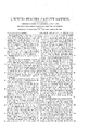
- Figure l is a side elevation of the machine.
- Fig. 2 is a view of the t-op of the machine.
- Fig. 3 is a view of the under side of two of the cars to which the links are attached.
- my invention consists in connecting together by means of hooks and links or links and eyes a train of four wheel cars into an endless train, which is placed in an endless space a little wider than the diameter of the car wheels inclosed by four endless tracks which I shall designate as the quadruple endless vertical railway, and endless train of rail road cars to be propelled by animals or any other required power to propel the sameplaced upon said endless train.
- I construct a frame A of suitable size and strength, of wood or iron containing four parallel endless tracks B about eight feet eight inches in length, the two inner ones being placed about eight inches apart, the ends of which tracks are connected by semicircles C.
- the two outer tracks B2 are placed four and an eighth of an inch distant from the inner tracks B connected at each end in the same manner as the inner tracks.
- the frame being composed of like parts on each side leaves an oblong groove or space within the tracks B of an inch in depth by four and an eighth of an inch wide that admits of the wheels of the cars passing around in said grooves or spacethe bodies of the cars being fourteen inches wide and sixteen inches long with a cavity D in the middle six by eight inches with an eye E at each end of the square to receive a link F that couples the cars together; the eye must be on a line transversely with the axis of the car wheels which will admit the cars dropping to a level 0n the planes of the tracks and possessing a pliability that will allow the cars to be propelled around the curved ends of the railway or tracks B.
- I raise the upper surface of the cars on their sides one inch sloping the said projection inward so as to form a groove to receive the wood floor, the side left open being for the purpose of inserting the said wood floor.
- I proceed to connect the cars together passing them into the spaces between the endless tracks by means of an opening at one end or in any other convenient way-the wheels of the cars keeping their places in every position on and in the tracks by means of the aforesaid quadruple rail road.
- the cars are composed wholly of cast and wrought iron except the floor. The whole to be governed in its dimensions as shall best suit the wishes of the builder, and answer the purpose for which it is intended. rIhe rack together with the frame and legs to give the power a proper inclination I build in any of the usual modes of constructing them.
- this horse power is as follows: The machine being placed at a proper angle of inclination with the horizon, and the propelling animal placed thereon isv caused to movehis limbs and his feet being in contact with the woodwork or floor of the cars, his shoes are not so liable to be injured, nor is the work near so hard to perform, nor so distressing to the animal as in the use of the common cast iron floor.
- the cars are caused t0 travel around in the endless way between the outer and inner track and upon the inner surface of the lower part of the outer track and the rack of the cars being in gear with the pinions on the axle of the band Wheel W to turn from which the power may be conveyed to any machinery required to be propelled.
Landscapes
- Health & Medical Sciences (AREA)
- Cardiology (AREA)
- Vascular Medicine (AREA)
- General Health & Medical Sciences (AREA)
- Physical Education & Sports Medicine (AREA)
- Road Paving Structures (AREA)
Description
III
rar ortica..
JEREMIAH M. REED, OF MIDDLEFIELD, NEW YORK.
ENDLESS-FLOR HORSE-POWER FOR DRIVING MACHINERY.
To all 'whom t may concern.'
Be it known that I, JEREMIAH M. REED, of Middlefield, in the county of Otsego and State of New York, have invented a new and useful Improvement on Inclined Endless Flexible Animal Tread-Powers; and I do hereby declare that the following is a full and exact description thereof, reference being had to the annexed drawings of the same, making part of this specification.
Figure l is a side elevation of the machine. Fig. 2 is a view of the t-op of the machine. Fig. 3 is a view of the under side of two of the cars to which the links are attached.
Similar letters refer to similar parts in the figures.
The nature of my invention consists in connecting together by means of hooks and links or links and eyes a train of four wheel cars into an endless train, which is placed in an endless space a little wider than the diameter of the car wheels inclosed by four endless tracks which I shall designate as the quadruple endless vertical railway, and endless train of rail road cars to be propelled by animals or any other required power to propel the sameplaced upon said endless train.
To enable others skilled in the art to make and use my invention I will proceed to describe its construction and operation.
I construct a frame A of suitable size and strength, of wood or iron containing four parallel endless tracks B about eight feet eight inches in length, the two inner ones being placed about eight inches apart, the ends of which tracks are connected by semicircles C. The two outer tracks B2 are placed four and an eighth of an inch distant from the inner tracks B connected at each end in the same manner as the inner tracks. The frame being composed of like parts on each side leaves an oblong groove or space within the tracks B of an inch in depth by four and an eighth of an inch wide that admits of the wheels of the cars passing around in said grooves or spacethe bodies of the cars being fourteen inches wide and sixteen inches long with a cavity D in the middle six by eight inches with an eye E at each end of the square to receive a link F that couples the cars together; the eye must be on a line transversely with the axis of the car wheels which will admit the cars dropping to a level 0n the planes of the tracks and possessing a pliability that will allow the cars to be propelled around the curved ends of the railway or tracks B. On the under side of the cars Gr and at each side thereof I aifix a rack H fitted to the pinions of the band wheel shaft I which pinions are placed on a shaft lying across the frame between the planes of the inner tracks or rails; these pinions are six inches in diameter which give a band wheel W of four feet a quick and powerful motion. The wheels K of these cars are four inches in diameter, one inch thick on their tread with a ledge or flange projecting three fourths of an inch above the tread of the wheels. These wheels are placed on axles one fourth of the length of the cars from each corner and in a straight line and level with the eyes of the connecting links. I raise the upper surface of the cars on their sides one inch sloping the said projection inward so as to form a groove to receive the wood floor, the side left open being for the purpose of inserting the said wood floor. I proceed to connect the cars together passing them into the spaces between the endless tracks by means of an opening at one end or in any other convenient way-the wheels of the cars keeping their places in every position on and in the tracks by means of the aforesaid quadruple rail road. The cars are composed wholly of cast and wrought iron except the floor. The whole to be governed in its dimensions as shall best suit the wishes of the builder, and answer the purpose for which it is intended. rIhe rack together with the frame and legs to give the power a proper inclination I build in any of the usual modes of constructing them.
The operation of this horse power is as follows: The machine being placed at a proper angle of inclination with the horizon, and the propelling animal placed thereon isv caused to movehis limbs and his feet being in contact with the woodwork or floor of the cars, his shoes are not so liable to be injured, nor is the work near so hard to perform, nor so distressing to the animal as in the use of the common cast iron floor. The cars are caused t0 travel around in the endless way between the outer and inner track and upon the inner surface of the lower part of the outer track and the rack of the cars being in gear with the pinions on the axle of the band Wheel W to turn from which the power may be conveyed to any machinery required to be propelled.
Vhat I claim as my invention and which` 5 I desire to secure by Letters Patent is- The making the endless chain upon which the horse, &c., Walks by uniting together in the manner described a suficient number of
Publications (1)
| Publication Number | Publication Date |
|---|---|
| US1963A true US1963A (en) | 1841-01-30 |
Family
ID=2062252
Family Applications (1)
| Application Number | Title | Priority Date | Filing Date |
|---|---|---|---|
| US1963D Expired - Lifetime US1963A (en) | Endless-floor horse-power for driving machinery |
Country Status (1)
| Country | Link |
|---|---|
| US (1) | US1963A (en) |
Cited By (1)
| Publication number | Priority date | Publication date | Assignee | Title |
|---|---|---|---|---|
| DE102008000494A1 (en) | 2008-03-03 | 2009-09-10 | Alstom Technology Ltd. | Gas tight electric bushing for use in gas-cooled electrical generator, has sleeve with front side loosely surrounding electrical conductor, and bush, funnel-shaped element and sleeve consisting of electric insulating material |
-
0
- US US1963D patent/US1963A/en not_active Expired - Lifetime
Cited By (1)
| Publication number | Priority date | Publication date | Assignee | Title |
|---|---|---|---|---|
| DE102008000494A1 (en) | 2008-03-03 | 2009-09-10 | Alstom Technology Ltd. | Gas tight electric bushing for use in gas-cooled electrical generator, has sleeve with front side loosely surrounding electrical conductor, and bush, funnel-shaped element and sleeve consisting of electric insulating material |
Similar Documents
| Publication | Publication Date | Title |
|---|---|---|
| US1963A (en) | Endless-floor horse-power for driving machinery | |
| US296998A (en) | Road-engine | |
| US754409A (en) | Traction-engine. | |
| US7094A (en) | Connecting trucks with car-bodies | |
| US1264738A (en) | Amusement or pleasure wheel. | |
| US103102A (en) | Improved traction-machine for plows | |
| US209451A (en) | Improvement in endless-track wheels for vehicles | |
| US7427A (en) | Gideon morgan | |
| US946730A (en) | Amusement apparatus. | |
| US277994A (en) | Locomotive | |
| US318360A (en) | Half to john f | |
| US312626A (en) | Apparatus for laying railroad-tracks | |
| US384658A (en) | Toy locomotive | |
| US301978A (en) | fee-tel | |
| US229702A (en) | Geobge f | |
| US34369A (en) | Improvement in velocipede ice-boats | |
| US3159A (en) | Hoeace wood | |
| US396862A (en) | Territory | |
| US18781A (en) | Propelling cars and carriages by horse-power | |
| US53209A (en) | Improvement in propelling wheeled vehicles | |
| US1130556A (en) | Moving stairway. | |
| US6064A (en) | Railroad-truck | |
| US387945A (en) | Horse-power | |
| US282197A (en) | Traction-engine | |
| US393771A (en) | Elevated railroad |