US1961964A - Electric lamp - Google Patents
Electric lamp Download PDFInfo
- Publication number
- US1961964A US1961964A US237624A US23762427A US1961964A US 1961964 A US1961964 A US 1961964A US 237624 A US237624 A US 237624A US 23762427 A US23762427 A US 23762427A US 1961964 A US1961964 A US 1961964A
- Authority
- US
- United States
- Prior art keywords
- bulb
- light source
- filament
- reflector
- rays
- Prior art date
- Legal status (The legal status is an assumption and is not a legal conclusion. Google has not performed a legal analysis and makes no representation as to the accuracy of the status listed.)
- Expired - Lifetime
Links
- 238000005286 illumination Methods 0.000 description 11
- 238000010276 construction Methods 0.000 description 10
- 239000011521 glass Substances 0.000 description 7
- 230000015572 biosynthetic process Effects 0.000 description 4
- 230000004313 glare Effects 0.000 description 3
- 238000009434 installation Methods 0.000 description 2
- 230000001174 ascending effect Effects 0.000 description 1
- 230000000903 blocking effect Effects 0.000 description 1
- 230000004048 modification Effects 0.000 description 1
- 238000012986 modification Methods 0.000 description 1
Images
Classifications
-
- H—ELECTRICITY
- H01—ELECTRIC ELEMENTS
- H01K—ELECTRIC INCANDESCENT LAMPS
- H01K1/00—Details
- H01K1/28—Envelopes; Vessels
- H01K1/30—Envelopes; Vessels incorporating lenses
-
- H—ELECTRICITY
- H01—ELECTRIC ELEMENTS
- H01K—ELECTRIC INCANDESCENT LAMPS
- H01K1/00—Details
- H01K1/26—Screens; Filters
Definitions
- My invention relates to electric lamps.
- One of the objects of my invention is to improve the light distribution of elastic lamps of the type comprising a transparent bulb, and a filament housed in said bulb.
- a further object of my invention is to improve the light distribution of electric bulbs used in connection with concave reflectors as in headlight construction.
- Figure 1 is an axial section through a parabolic reflector showing the bulb in position
- Fig. 2' is an enlarged view of the bulb shown in Fig. 1; 1
- Fig. 3 isan enlarged detail view of a small reflector shield in the bulb
- Fig. 4 is an axial section through a reflector showing a different form of bulb
- Fig. 5 is an enlarged view of the bulb shown in Fig. 4;
- Fig. 6 is an axial section through a reflector showing still another form of bulb
- Fig. 7 is an enlarged view of the bulb shown in Fig. 6;
- Fig. 8 is a section on the line 8-8 of Fig. 7.
- the construction shown therein comprises a parabolic reflector 1, and an electric lamp 2 mounted therein with the light center 3 substantially at or near the focus of the parabola so that light rays A from the source falling on the reflector are reflected therefrom in substantially parallel rays B to give a concentrated beam.
- the lamp base 4 itself may be of any usual or suitable construction and its connection with the socket portion 5 of the reflector may be of any usual or suitable construction.
- the axis of the bulb may be horizontal and in such installations there is usually a large proportion of the light from the filament which escapes forwardly through the open front of the reflector which serves very little useful purpose and which, in fact, is often harmful in that it causes a disagreeable and dangerous glare.
- the construction provided for this purpose comprises a concave reflector shield fi'within the bulb 7 mounted on the glass post 8 from which the filament 9 extends, this mounting being effected by means of a pair of slender supports 10 secured to opposite sides of the small reflector member.
- This reflector member is provided on its inner side with a reflecting surface, and this inher reflecting surface is substantially spherical,
- the center of the spherical surface being substantially at the center of the light source 3 so that rays C from this light source are reflected back substantially toward and through this light source so that they fall upon the main reflector at an angle which causes them to be reflected forwardly as substantially parallel rays.
- Figs. 1 and 2 the light filament is shown revolved 90 out of place for the sake of ilh stration. Particularly in a two filament bulb, it is customary to have the filaments lie in horizontal planes.
- Figs. 4 and 5 comprise a concave reflector 1 which may be similar to that described in connection with Fig. 1, and a lamp bulb 2 having a connection with the reflector similar to that described in Fig. 1.
- a concave reflector 1 which may be similar to that described in connection with Fig. 1, and a lamp bulb 2 having a connection with the reflector similar to that described in Fig. 1.
- no reflector member is provided inside the lamp bulb 7 but the forward end of the bulb is provided with a relatively large convex lens formation 14 of suincient extent to intercept substantially all of the light from the light source which does not fall upon the parabolic reflector 1.
- This lens condenses the conical beam which falls thereon from the light source and causes the rays E to converge so that the beam finally emerges as a relatively concentrated and forwardly directed beam.
- the construction shown in Figs. 6, 7, and 8, and the connection between the lamp bulb and reflector may be substantially as disclosed in the forms previously described.
- the glass filament enclosing bulb 7 is provided at its forward end with a lens formation 15 of sufficient extent to intercept substantially all of the light rays from the light source which do not fall on the main parabolic reflector 1.
- This lens acts in a manner similar to the lens 14 described in connection with Figs. 4 and 5 to condense the light beam falling thereon.
- I provide a small auxiliary reflector 16 within the bulb which may be mounted directly on the glass post 8 which carries the filament.
- This auxiliary reflector is concave, having a substantially spherical inner reflecting surface, the center of which is substantially in the center of the light source 3 so that rays F falling thereon are reflected back toward and through the light source, most of them falling on the condensing lens 15 to reinforce the beam emitted through this lens.
- this condensing lens may be cut away on both sides as indicated at 17, to permitsome of the rays to escape without substantial change of direction forwardly and laterally for illuminating road sides, etc.
- the lens 12 shown in Figs. 1 and 2 may be omitted, if desired, since the spread beam emitted through the small hole 12 will not be wide. It is obvious that a bulb can be made embodying both the reflectdrs shown in Figs. 2 and 7. In such a construction the rear mirror would be so designed that the greater part of the light reflected therefrom would clear-the front mirror.
- a double filament bulb may have special advantages in connection with the constructions disclosed and in Figs. 4 and 5 I have shown two filaments 18, one above the other, one of which may be used as a driving light when no one is approaching and the other of which may be used to avoid glare when a driver is approaching from the opposite direction.
- An electric lamp comprising a transparent bulb, a filament housed in said bulb, a base for said lamp at the rear end of the bulb, and a reflector in said bulb in front of the filament, said reflector being of circular formation with a portion cut away at the side to permit direct forward and side illumination.
- An electric lamp comprising a transparent bulb and a filament housed in said bulb, a base for said lamp at the rear end of the bulb, said filament having substantially a point light source and a sphericahreflector in said bulb in front of said light source and between the light source and the front portion of the bulb and having said light source as its center for directing the rays falling thereon back toward and past the light source to increase the rearwardly directed illumination, said reflector being cut away at the side from a point below the level of the light source to a point above the level of the light source to permit some direct forward and upward illumination.
- An electric lamp for automobile headlamps comprising a transparent bulb and a filament housed in said bulb, a base for said lamp at the rear end of the bulb, said filament having substantially a point light source and a spherical reflecting shield in said bulb locatedclose to the filament in front of said light source only and between the light source and the front portion of the bulb and having said light source as its center for directing the rays falling thereon back toward and past the light source to increase the rearwardly directed illumination, means for supporting said shield from said base while leaving the space behind and at the sides of said filament substantially unobstructed, so that laterally and rearwardly directed rays as well as rays reflected from said shield may pass freely out of said bulb, said shield having a light-emitting aperture at its center portion to enable direct central forward illumination to reduce the shadow cast by said reflector.
- An electric lamp comprising a transparent bulb and a filament housed in said bulb, a base for said lamp at the rear end of the bulb, said filament having substantially a point light source and a spherical reflector in said bulb in front of said light source and between the light source and the front portion of the bulb and having said light source as its center for directing the rays falling thereon back'toward and past the light source to increase the rearwardly directed illumination, the path of said rays so directed back being substantially unobstructed except for said base, said bulb having a glass postextending from the base on which the filament is mounted and supporting stems mounted on the glass post and extending forwardly of the point light source for supporting the spherical reflector.
- An electric lamp comprising a transparent bulb, a filament housed in said bulb, a base for said lamp at the rear end of the bulb, and a shield in said bulb in front of the filament, said shield being of circular formation with a portion cut away at the side to permit direct forward and side illumination and having a small aperture at its center.
- An electric lamp comprising a transparent bulb and a filament housed in said bulb, a base for said lamp at the rear end of the bulb, said filament having substantially a point light source and a circular reflector shield in said bulb in front of said light source and between the light source and the front portion of the bulb and having said light source as its center for directing the rays falling thereon back toward and past the light source to increase the rearwardly directed illumination, said shield being cut away at the side from a point below the level of the light sourceto a point above the level of the light source to permit some direct forward and upward illumination.
- An electric lamp comprising a transparent bulb and a filament housed in said bulb, a base for said lamp at the rear end of the bulb, said filament having substantially a point light source, and a spherical reflecting shield in said bulb located closely in front of said light source, said light source being substantially at the center of said shield, said shield having a small lightemitting aperture at its center portion to emit direct center forward illumination to partly overcome the shadow cast by the shield, said bulb being arranged to permit unobstructed passage of rays around the sides of said shield.
- a small spherical reflecting segment set close to the filament blocking the forwardly ascending rays and reflecting them back through the light source and also the central part of the forwardly descending rays, said spherical segment being cut away at the sides to pass a portion of said forwardly descending rays to the right and to the left forwardly and substantially downwardly to illuminate the edge of the road at close proximity to an automobile in which the bulb may be.
- An electric bulb for an automobile headlamp having a glass bulb, a base and a light filament, and a substantially circular shield located directly in front of said light filament to block forwardly emitting rays in proximity close to the axis of bulb, said shield having its edge cut away at one side below the center line for the emission of forward and side illumination, and having a small aperture in its center lessening the shadow cast by the shield.
Landscapes
- Non-Portable Lighting Devices Or Systems Thereof (AREA)
Description
A. Y. DODGE June 5, 1934.
ELECTRIC LAMP Filed Dec. 5, 1927 PatentedJune 5, 1934 PATENT OFFICE ELECTRIC LAMP Adiel Y. Dodge, South Bend, Ind. Application December 5, 1927, Serial No. 237,624
9 Claims.
My invention relates to electric lamps.
One of the objects of my invention is to improve the light distribution of elastic lamps of the type comprising a transparent bulb, and a filament housed in said bulb.
A further object of my invention is to improve the light distribution of electric bulbs used in connection with concave reflectors as in headlight construction.
Further objects will appear from the description and claims.
In the drawing, in which seve al embodiments of my invention are shown,
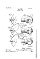
Figure 1 is an axial section through a parabolic reflector showing the bulb in position;
Fig. 2'is an enlarged view of the bulb shown in Fig. 1; 1
Fig. 3 isan enlarged detail view of a small reflector shield in the bulb;
Fig. 4 is an axial section through a reflector showing a different form of bulb;
Fig. 5 is an enlarged view of the bulb shown in Fig. 4;
Fig. 6 is an axial section through a reflector showing still another form of bulb;
Fig. 7 is an enlarged view of the bulb shown in Fig. 6; and
Fig. 8 is a section on the line 8-8 of Fig. 7.
Referring to the drawing in detail, and first to Figs. 1, 2 and 3, the construction shown therein comprises a parabolic reflector 1, and an electric lamp 2 mounted therein with the light center 3 substantially at or near the focus of the parabola so that light rays A from the source falling on the reflector are reflected therefrom in substantially parallel rays B to give a concentrated beam. The lamp base 4 itself may be of any usual or suitable construction and its connection with the socket portion 5 of the reflector may be of any usual or suitable construction. In certain installations, such as headlights forautomobiles, the axis of the bulb may be horizontal and in such installations there is usually a large proportion of the light from the filament which escapes forwardly through the open front of the reflector which serves very little useful purpose and which, in fact, is often harmful in that it causes a disagreeable and dangerous glare.
In my improved bulb means are providedto utilize a large proportion of light which would otherwise be wasted and also to minimize the glare. The construction provided for this purpose comprises a concave reflector shield fi'within the bulb 7 mounted on the glass post 8 from which the filament 9 extends, this mounting being effected by means of a pair of slender supports 10 secured to opposite sides of the small reflector member. This reflector member is provided on its inner side with a reflecting surface, and this inher reflecting surface is substantially spherical,
the center of the spherical surface being substantially at the center of the light source 3 so that rays C from this light source are reflected back substantially toward and through this light source so that they fall upon the main reflector at an angle which causes them to be reflected forwardly as substantially parallel rays. I also find it advantageous to provide a small circular opening 11 in the middle of the large auxiliary reflector 6 which permits some direct rays D to escape forwardly therethrough and fall upon a lens construction 12 which may ,be formed integral with the glass enclosing bulb 7. I also flnd it advantageous to cut away the sides of the large auxiliary reflector 6, as shown at 13, to permit a certain amount of forwardly and laterally directed rays to escape directly to illuminate the side of the roadway.
In Figs. 1 and 2 the light filament is shown revolved 90 out of place for the sake of ilh stration. Particularly in a two filament bulb, it is customary to have the filaments lie in horizontal planes.
The constructions shown in Figs. 4 and 5 comprise a concave reflector 1 which may be similar to that described in connection with Fig. 1, and a lamp bulb 2 having a connection with the reflector similar to that described in Fig. 1. In this form no reflector member is provided inside the lamp bulb 7 but the forward end of the bulb is provided with a relatively large convex lens formation 14 of suincient extent to intercept substantially all of the light from the light source which does not fall upon the parabolic reflector 1. This lens condenses the conical beam which falls thereon from the light source and causes the rays E to converge so that the beam finally emerges as a relatively concentrated and forwardly directed beam.
The construction shown in Figs. 6, 7, and 8, and the connection between the lamp bulb and reflector may be substantially as disclosed in the forms previously described. The glass filament enclosing bulb 7 is provided at its forward end with a lens formation 15 of sufficient extent to intercept substantially all of the light rays from the light source which do not fall on the main parabolic reflector 1. This lens acts in a manner similar to the lens 14 described in connection with Figs. 4 and 5 to condense the light beam falling thereon. In this form I provide a small auxiliary reflector 16 within the bulb which may be mounted directly on the glass post 8 which carries the filament. This auxiliary reflector is concave, having a substantially spherical inner reflecting surface, the center of which is substantially in the center of the light source 3 so that rays F falling thereon are reflected back toward and through the light source, most of them falling on the condensing lens 15 to reinforce the beam emitted through this lens. If desired, this condensing lens may be cut away on both sides as indicated at 17, to permitsome of the rays to escape without substantial change of direction forwardly and laterally for illuminating road sides, etc.
The lens 12 shown in Figs. 1 and 2 may be omitted, if desired, since the spread beam emitted through the small hole 12 will not be wide. It is obvious that a bulb can be made embodying both the reflectdrs shown in Figs. 2 and 7. In such a construction the rear mirror would be so designed that the greater part of the light reflected therefrom would clear-the front mirror.
A double filament bulb may have special advantages in connection with the constructions disclosed and in Figs. 4 and 5 I have shown two filaments 18, one above the other, one of which may be used as a driving light when no one is approaching and the other of which may be used to avoid glare when a driver is approaching from the opposite direction.
While I have described but one embodiment of my invention, it is obvious that many modifications therein may occur to those skilled in the art, and I desire, therefore, that my invention be limited only by the scope of the appended claims and by the prior art.
I claim:
1. An electric lamp comprising a transparent bulb, a filament housed in said bulb, a base for said lamp at the rear end of the bulb, and a reflector in said bulb in front of the filament, said reflector being of circular formation with a portion cut away at the side to permit direct forward and side illumination.
2. An electric lamp comprising a transparent bulb and a filament housed in said bulb, a base for said lamp at the rear end of the bulb, said filament having substantially a point light source and a sphericahreflector in said bulb in front of said light source and between the light source and the front portion of the bulb and having said light source as its center for directing the rays falling thereon back toward and past the light source to increase the rearwardly directed illumination, said reflector being cut away at the side from a point below the level of the light source to a point above the level of the light source to permit some direct forward and upward illumination.
3. An electric lamp for automobile headlamps comprising a transparent bulb and a filament housed in said bulb, a base for said lamp at the rear end of the bulb, said filament having substantially a point light source and a spherical reflecting shield in said bulb locatedclose to the filament in front of said light source only and between the light source and the front portion of the bulb and having said light source as its center for directing the rays falling thereon back toward and past the light source to increase the rearwardly directed illumination, means for supporting said shield from said base while leaving the space behind and at the sides of said filament substantially unobstructed, so that laterally and rearwardly directed rays as well as rays reflected from said shield may pass freely out of said bulb, said shield having a light-emitting aperture at its center portion to enable direct central forward illumination to reduce the shadow cast by said reflector.
4. An electric lamp comprising a transparent bulb and a filament housed in said bulb, a base for said lamp at the rear end of the bulb, said filament having substantially a point light source and a spherical reflector in said bulb in front of said light source and between the light source and the front portion of the bulb and having said light source as its center for directing the rays falling thereon back'toward and past the light source to increase the rearwardly directed illumination, the path of said rays so directed back being substantially unobstructed except for said base, said bulb having a glass postextending from the base on which the filament is mounted and supporting stems mounted on the glass post and extending forwardly of the point light source for supporting the spherical reflector.
5. An electric lamp comprising a transparent bulb, a filament housed in said bulb, a base for said lamp at the rear end of the bulb, and a shield in said bulb in front of the filament, said shield being of circular formation with a portion cut away at the side to permit direct forward and side illumination and having a small aperture at its center.
6. An electric lamp comprising a transparent bulb and a filament housed in said bulb, a base for said lamp at the rear end of the bulb, said filament having substantially a point light source and a circular reflector shield in said bulb in front of said light source and between the light source and the front portion of the bulb and having said light source as its center for directing the rays falling thereon back toward and past the light source to increase the rearwardly directed illumination, said shield being cut away at the side from a point below the level of the light sourceto a point above the level of the light source to permit some direct forward and upward illumination.
7. An electric lamp comprising a transparent bulb and a filament housed in said bulb, a base for said lamp at the rear end of the bulb, said filament having substantially a point light source, and a spherical reflecting shield in said bulb located closely in front of said light source, said light source being substantially at the center of said shield, said shield having a small lightemitting aperture at its center portion to emit direct center forward illumination to partly overcome the shadow cast by the shield, said bulb being arranged to permit unobstructed passage of rays around the sides of said shield.
8. In an automobile headlamp bulb, a small spherical reflecting segment set close to the filament blocking the forwardly ascending rays and reflecting them back through the light source and also the central part of the forwardly descending rays, said spherical segment being cut away at the sides to pass a portion of said forwardly descending rays to the right and to the left forwardly and substantially downwardly to illuminate the edge of the road at close proximity to an automobile in which the bulb may be.
9. An electric bulb for an automobile headlamp having a glass bulb, a base and a light filament, and a substantially circular shield located directly in front of said light filament to block forwardly emitting rays in proximity close to the axis of bulb, said shield having its edge cut away at one side below the center line for the emission of forward and side illumination, and having a small aperture in its center lessening the shadow cast by the shield.
. ADIEL Y. DODGE.
Priority Applications (1)
| Application Number | Priority Date | Filing Date | Title |
|---|---|---|---|
| US237624A US1961964A (en) | 1927-12-05 | 1927-12-05 | Electric lamp |
Applications Claiming Priority (1)
| Application Number | Priority Date | Filing Date | Title |
|---|---|---|---|
| US237624A US1961964A (en) | 1927-12-05 | 1927-12-05 | Electric lamp |
Publications (1)
| Publication Number | Publication Date |
|---|---|
| US1961964A true US1961964A (en) | 1934-06-05 |
Family
ID=22894495
Family Applications (1)
| Application Number | Title | Priority Date | Filing Date |
|---|---|---|---|
| US237624A Expired - Lifetime US1961964A (en) | 1927-12-05 | 1927-12-05 | Electric lamp |
Country Status (1)
| Country | Link |
|---|---|
| US (1) | US1961964A (en) |
Cited By (8)
| Publication number | Priority date | Publication date | Assignee | Title |
|---|---|---|---|---|
| US2419961A (en) * | 1944-06-09 | 1947-05-06 | Julian A Links | Motion-picture projection apparatus |
| US3144993A (en) * | 1959-06-02 | 1964-08-18 | Sassmannshausen Knut | Search light |
| DE1276927B (en) * | 1957-12-09 | 1968-09-05 | Sylvania Electric Prod | Projection lamp with built-in reflector |
| DE1287032B (en) * | 1964-02-21 | 1969-01-16 | Sassmannshausen Knuth | Close-up light |
| US4611143A (en) * | 1983-05-24 | 1986-09-09 | Hamamatsu Photonics Kabushiki Kaisha | Composite light source |
| EP0534606A1 (en) * | 1991-08-29 | 1993-03-31 | General Electric Company | Electric lamps having a lens shaped arc or filament chamber |
| US20070063655A1 (en) * | 2003-05-12 | 2007-03-22 | Koninklijke Philips Electronics N.V. | Lamp for a motor vehicle headlight |
| US7349103B1 (en) | 2005-10-31 | 2008-03-25 | N&K Technology, Inc. | System and method for high intensity small spot optical metrology |
-
1927
- 1927-12-05 US US237624A patent/US1961964A/en not_active Expired - Lifetime
Cited By (8)
| Publication number | Priority date | Publication date | Assignee | Title |
|---|---|---|---|---|
| US2419961A (en) * | 1944-06-09 | 1947-05-06 | Julian A Links | Motion-picture projection apparatus |
| DE1276927B (en) * | 1957-12-09 | 1968-09-05 | Sylvania Electric Prod | Projection lamp with built-in reflector |
| US3144993A (en) * | 1959-06-02 | 1964-08-18 | Sassmannshausen Knut | Search light |
| DE1287032B (en) * | 1964-02-21 | 1969-01-16 | Sassmannshausen Knuth | Close-up light |
| US4611143A (en) * | 1983-05-24 | 1986-09-09 | Hamamatsu Photonics Kabushiki Kaisha | Composite light source |
| EP0534606A1 (en) * | 1991-08-29 | 1993-03-31 | General Electric Company | Electric lamps having a lens shaped arc or filament chamber |
| US20070063655A1 (en) * | 2003-05-12 | 2007-03-22 | Koninklijke Philips Electronics N.V. | Lamp for a motor vehicle headlight |
| US7349103B1 (en) | 2005-10-31 | 2008-03-25 | N&K Technology, Inc. | System and method for high intensity small spot optical metrology |
Similar Documents
| Publication | Publication Date | Title |
|---|---|---|
| US2277563A (en) | Vehicle headlamp | |
| US6494603B1 (en) | Headlamp for a vehicle | |
| US6435703B2 (en) | Vehicular headlamp | |
| US1998967A (en) | Headlight | |
| US6402355B1 (en) | Vehicular headlamp having improved low-beam illumination | |
| CN105276487A (en) | High beam and low beam integrated LED automobile lens | |
| US20070171665A1 (en) | High-intensity zone LED projector | |
| JPH09237504A (en) | Automotive headlights for downward and upward lights | |
| CN207196370U (en) | Lighting structure | |
| CN205118889U (en) | Integrative LED car lens of far and near light | |
| US2277685A (en) | Headlight, especially for automobiles and similar vehicles | |
| US1961964A (en) | Electric lamp | |
| US1867138A (en) | Electric light and headlight | |
| TWI642568B (en) | Illumination structure and light distribution method thereof | |
| US2228329A (en) | Automobile nonglare headlight | |
| US2020130A (en) | Vehicle headlight lamp | |
| US2858467A (en) | Vehicle headlamp | |
| GB1196109A (en) | Automobile Headlight | |
| US1712027A (en) | Light-projecting device | |
| US1947243A (en) | Electric lamp | |
| US1863547A (en) | Illuminating device | |
| JP7058166B2 (en) | Vehicle headlights | |
| US1451161A (en) | Headlight ifor automobiles | |
| CN213395128U (en) | Headlamp High Beam Lighting System | |
| US1635116A (en) | Headlight |