US1952182A - Grinding machine - Google Patents
Grinding machine Download PDFInfo
- Publication number
- US1952182A US1952182A US650276A US65027633A US1952182A US 1952182 A US1952182 A US 1952182A US 650276 A US650276 A US 650276A US 65027633 A US65027633 A US 65027633A US 1952182 A US1952182 A US 1952182A
- Authority
- US
- United States
- Prior art keywords
- wheel
- grinding
- carrier
- work
- throat
- Prior art date
- Legal status (The legal status is an assumption and is not a legal conclusion. Google has not performed a legal analysis and makes no representation as to the accuracy of the status listed.)
- Expired - Lifetime
Links
- 238000009740 moulding (composite fabrication) Methods 0.000 description 19
- 230000001105 regulatory effect Effects 0.000 description 6
- 230000000694 effects Effects 0.000 description 5
- 230000007246 mechanism Effects 0.000 description 5
- 230000001276 controlling effect Effects 0.000 description 4
- 230000008859 change Effects 0.000 description 3
- 230000009471 action Effects 0.000 description 2
- 230000008878 coupling Effects 0.000 description 2
- 238000010168 coupling process Methods 0.000 description 2
- 238000005859 coupling reaction Methods 0.000 description 2
- 238000012423 maintenance Methods 0.000 description 2
- 239000003082 abrasive agent Substances 0.000 description 1
- 238000010276 construction Methods 0.000 description 1
- 239000002826 coolant Substances 0.000 description 1
- 238000009413 insulation Methods 0.000 description 1
- 238000003754 machining Methods 0.000 description 1
- 238000004519 manufacturing process Methods 0.000 description 1
- 239000000463 material Substances 0.000 description 1
- 230000004048 modification Effects 0.000 description 1
- 238000012986 modification Methods 0.000 description 1
- 230000000284 resting effect Effects 0.000 description 1
Images

Classifications
-
- B—PERFORMING OPERATIONS; TRANSPORTING
- B24—GRINDING; POLISHING
- B24B—MACHINES, DEVICES, OR PROCESSES FOR GRINDING OR POLISHING; DRESSING OR CONDITIONING OF ABRADING SURFACES; FEEDING OF GRINDING, POLISHING, OR LAPPING AGENTS
- B24B5/00—Machines or devices designed for grinding surfaces of revolution on work, including those which also grind adjacent plane surfaces; Accessories therefor
- B24B5/18—Machines or devices designed for grinding surfaces of revolution on work, including those which also grind adjacent plane surfaces; Accessories therefor involving centreless means for supporting, guiding, floating or rotating work
Definitions
- This invention relates to improvements in machine tools and especially to improvements in grinding machines.
- An object of this invention is the provision of a grinding machine of the centerless type for continuously producing circular work pieces.
- Another object of the invention is the provision of a centerless grinder adapted for simultaneously operating on a plurality of work pieces together with independent means for controlling individual work pieces.
- a further object of the invention is the provision of a centerless grinder including a plurality of independent units for operation-on individual work pieces, together with a single work 1'0- tation controlling unit.
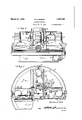
- Figure 6 is a view partly in section and partly in elevation, as seen from line 66 on Figure 3.
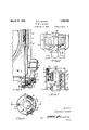
- Figure 7 is an. enlarged sectional View through mechanism utilized with the machine and forming a detail of the invention, the View being taken on line 7-'7 of Figure 8.
- Figure 8 is a vertical sectional view taken on line 8-8 of Figure '7.
- the machine of this invention pertains to a centerless grinding machinein which (Cl. 5l--103) machine.
- Associated with each of the independ- 6 cut wheel heads is mechanism for controlling the feed of the work piece being operated upon thereby.
- the machine comprises a base plate having fo med centrally thereof an aperture 16 forming at right angles thereto a seat 17.
- a post or column member 18 is provided, being received in the aperture 16 and having formed integral therewith a circular flange 19 resting on the base seat 17, suitable clamp screws 20 being utilized for securing the post 18 to the base 15.
- a sleeve 21 into the upper end of which is pressed a bushing 22 that engages the upper end of the post or column 18.
- a clamp collar 23 Keyed or otherwise secured to the post or column 18 at its upper end is a clamp collar 23 having formed integral therewith a flange 24, the upper surface of which is tapered or inclined as shownat 25.
- the collar 23 lies on the upper surface of a flange 26 formed integral with the spindle sleeve 21 and this flange is pro-' videdwith an inclined surface27 similar but opposite to the inclined face of the collar 23.
- a split clamp ring 28 Encircling the flanges 24 and 26 is a split clamp ring 28 having a tapered internal groove simultaneously engaging the inclined faces 25 and 27 of the flanges 245 and 26.
- a suitable clamp or draw bolt 29' is provided for drawing the ends of the split clamp ring 28 toward one another, which through the co-operating inclined faces of the clamping collar and flange securely clamps the spindle sleeve 21 to the collar 23 and thereby normally holds the spindle sleeve stationary.
- the spindle sleeve 21 is provided with a wheel mount, here shown as an integral flange 30 having formed thereon a seat to receive an internal flange 31 on the wheel 32.
- the wheel 32 may be formed of any suitable material for frictionally engaging the work, as will later appear, and in practice it has been found abrasive material is suitable for the purpose.
- the wheel is secured to the mount 30 by means of clamp plate 33 keyed or otherwise secured to the spindle sleeve 21 above the mount 30;
- a driving sleeve 34 Surrounding the spindle sleeve 21 is a driving sleeve 34 into which is pressed bushings 35 and 36 engaging bearing surfaces formed exteriorly of the spindle sleeve 21. Keyed or otherwise secured to the driving sleeve 34 intermediate its ends is a pulley 37, here shown as a sheave of the multiple V-belt type.
- a seat for an anti-friction thrust bearing 38 supporting the spindle sleeve 21 and engaging the under surface of the wheel mount 30.
- the lower end of the driving sleeve 34 is provided with clutch teeth 39 adapted to be meshed with clutch teeth 40 formed on shiftablc clutch member 41.
- the clutch member 41 is keyed for sliding movement to the spindle 21 and is provided on its exterior surface with a circumferential groove 42 receiving the usual clutch shifter dog mounted on clutch shaft operable by means of the handle 43, accessible exteriorly of the machine.
- Extending about the sheave or pulley 3'7 of the driving shaft 34 are a plurality of belts 44 which are in turn trained about a sheave 45 secured to one end of a motor shaft 46 associated with prime mover or motor 47.
- the motor 47 is supported by a carrier member which is rotatable relative to the base 15.
- a pair of bushings 48 and 49 respectively carried by a sleeve or column 50 integral with a carrier designated in its entirety by the numeral 51.
- the column 50 is further provided at its lower end with a bushing or bearing 52 that surrounds a circular bearing formed on the sleeve or post 18 near its lower end.
- the bearing 52 is provided with a flange 53 riding on an anti-friction thrust bearing 54A carried by the flange 19 of the post 18.
- the upper surface of the column 50 is provided with a circular seat 50a receiving thereon an anti-friction thrust bearing 5% which engages on its other side with a shoulder 59c formed on the driving sleeve 34.
- the carrier has integral therewith a radial flange 54 to which is secured in any desirable manner a worm wheel 55 meshing with a worm 56 on one end of a worm shaft 57.
- the worm shaft 57 is journaled in bearings 58 provided by the base 15, see
- the gear box 59 encloses the gears designated in their entirety by the 'numeral 60 of which the final and change gear 61 is keyed or otherwise secured to the shaft 57 which meshes with the change gear or pinion 62 mounted on a stud secured to a quadrant 63 adjustably pivotally mounted within the gear box 59.
- the gear trains 60 terminate in a suitable gear meshing with a pinion 64 keyed or otherwise secured to the shaft 65 rotatably mounted in bearings provided by the gear box 59.
- the shaft 65 is connected through coupling 56 to the shaft of the prime mover or motor 67 secured to the exterior surface of the base 15.
- the carrier 51 is rotated around the sleeve or post 18 and at different speeds depending upon the ratio between the two sets of change gears 61 and pinions 62. It will be further noted that the carrier is amply supported on plain and anti-friction bearings to insure the easy, free rotation thereof.
- the carrier 51 is provided with a guideway 68 of dove-tailed cross section which is interrupted intermediate its ends to form a pocket 69.
- a slide 70 having secured in its outer end a nut 71 meshing with the threads of an adjusting screw 72 rotatably journaled in a bracket 73 secured to the carrier at the end of the guideway 68.
- a hand wheel 74 is secured to the end of the screw projecting outwardly beyond the bearing 73. Rotation of the screw 72 in a given direction advances the slide 70 and parts carried thereby toward the central sleeve or post 18 or retracts the said parts from said post.
- the upper surface of the slide 70 see Figure 1, is provided with an arcuate seat 75 receiving therein a cradle or carriage 76.
- the carriage 76 is provided exteriorly and longitudinally thereof with flanges 77 and '28 through which pass clamping bolts or screws 79 having their heads received in a T-shaped slot 89 formed in the slide 79 below the arcuate seat 75.
- the carriage 76 is provided with bearings 81 and 82 in which is journaled a spindle 83.
- One end of the spindle 83 is of tapered form receiving thereon a grinding wheel mount 84 to which is secured the grinding wheel 85.
- the spindle bearing 81 extends through an elongated perforation 86 formed in the carriage 70 into the pocket 69 formed in the carrier 51.
- each of the grinding wheels has its operative surface spaced from the operative face of the friction or control wheel 32 a distance representative of the finished size of the work to be operated upon. -As will later appear, the work is inserted into the grinding throat and operated thereon and fed through the throat by the combined action of said wheels. The rate of feed of the work is controlled by the amount of inclination between the faces of the grinding wheels and friction control or regulating wheel 32. From the above description it will be noted that the carriage or cradle may be adjusted to effect and determine the feed of the work by shifting said carriage relative to the arcuate seat 75. After the desired adjustment is had, the parts are secured in position by the clamping bolts 79.
- the said spindle In order to rotate the spindle 83 and consequently the grinding wheel 85, the said spindle has keyed or otherwise secured to it intermediate the bearings 81 and 82 a pulley or sheave 87, here shown as of the multiple V-type, about which is trained a plurality of V-type belts 88.
- the belts 83 are in turn extended about a driving sheave 89 keyed or otherwise secured to the shaft 90 of prime mover or motor 91.
- the motor 91 is provided at one end with a radial flange 92 received on a suitable seat 93 provided by the cradle or carriage 76.
- arouate adjustment of the carriage 76 not only adjusts the position of the spindle 83, but also the motor 91, thereby at all times and regardless of a mechanism is shifted through an arcuate path concentric with the periphery of the wheel 32, and, as seen in Figure 6, comprises a bracket 94 secured to the carrier 51 at the inner end of the slide to which bracket is adjustably secured an upstanding frame 95.
- the frame 95 in turn has adjustably secured to it blades 96 and 97 which are adapted to be adjusted with respect to one another to provide between them a space sub stantially equal to the diameter of the work to be operated upon.
- Above the grinding throat'the frame 95 and blades 96 and 97 form a guide 98 through which the work is introduced into the grinding throat.
- rotation of the carrier 51 not only actuates the grinding wheel relative to the fixed regulating wheel 32, but also shifts the work through the agency of the blades 96 and 97 relative thereto.
- This shifting of the work causes the same to roll on the operative surface of the wheel 32 and thereby present the entire surface of the work to the, action of the grinding wheel.
- the grinding wheel 85 has its axis skewed as respects the axis of the regulating wheel 32 a feeding component will be exerted on the work thereby causing it to axially advance through the grinding throat.
- the work passes beyond the grinding throat through an aperture 99 formed in the bracket 94 into a discharge chute 100 formed in the inner end of the carriage or cradle 76.
- a finished work delivery trough 101 Secured to said inner end of the carriage 76 and in line with the discharge chute 100 is a finished work delivery trough 101 which extends along the side of the carriage at an angle thereto to the outer edge of the base 15.
- the discharge chute 101 terminates at a work receiving pocket 102 formed integral with the base 15 and from which pocket the finished work pieces are subsequently gathered.
- the regulating wheel truing motor is, as noted above mounted on the carrier 51 and, as seen in Figure 2, is disposed between two adjacent grinding heads or units and is, therefore, rotated with the carrier 51 around the axis of the post or column 18. Due to a possible unbalance in the several units and to overcome any possible slight inaccuracies or eccentricities that may exist between the sleeve or post 18, spindle sleeve 21 and column 50 of the carrier 51, the driving sleeve 34 is constantly rotated and since the said sleeve is driven at a higher rate of speed than the carrier 51 thereby continuously changes the relation of the several bearing surfaces and overcomes any possible ill effects caused by the possibe machining errors above noted. From this it will be seen that the grinding throat between lie several grinding wheels and the fixed friction or work controlling wheel is at all times maintained at the same desired size, thereby insuring the production of work pieces within fine limits of tolerance;
- the central sleeve or post 18 has secured to its upper end a collector ring mechanism comprising a carrier sleeve 103 encircled by an insulation bushing 104.
- a collector ring mechanism comprising a carrier sleeve 103 encircled by an insulation bushing 104.
- the current collector rings 105, 106 and 107 which, as shown in the drawings, are split and clamped in place by clamping screws 108.
- the rings 105, 106 and 107 have each secured to them a post 109 and respectively connected to one of the three lines of a three phase current system.
- the post 109 that is connected to the topmost ring 105 or posts 112 with the carrier 51.
- a brush holder housing 110 Surrounding the lower end of the sleeve 103 is a brush holder housing 110 connected through a radial flange 111, integral therewith, by bolts Interiorly of the brush holder housing 110 and near the upper end thereof it is provided with a flange 113 carrying the brush holders 114 which are three in number and spaced equally from one another.
- the brush holders 114 are each provided with a shoe or a pair of brushes 118 respectively contacting with one of the collector rings 105, 106 and 107. From each brush holder extends a wire that terminates at one of the binding posts associated with each motor.
- the brush holders 114 each carry at their upper end a coupling 115 which may conveniently be hexagonal in shape'and of which but five faces will be used since there are five motors that rotate with the carrier 51 and including the motors for each of the grinding wheel units and the motor for rotating the normally stationary friction control wheel.
- a rigid conduit is provided which, as shown in Figure 3, is mounted on a standard 116 secured to the cover 117 of the grinding wheel guards which, as is usual practice, substantially encloses the grinding wheel to confine the coolant usual with machines of this type.
- a grinding machine of the class the combination of a base, a fixed wheel carried thereby, a plurality of wheel heads each including a grinding wheel mounted on the base for rotary movement relative to the fixed wheel, the said grinding wheels forming with the fixed wheel a grind ng throat between them, and means for effecting the rotation of the wheel heads.
- a grinding machine of the class the combination of a base, a fixed wheel carried thereby, aplurality of wheel heads each including a grinding wheel mounted on the base for rotary movement relative to the fixed wheel, the said grinding wheels forming with the fixed wheel a grinding throat between them, means for effecting the rotation of the wheel heads, and means associated with each wheel head for effecting the feed of the work through the grinding throat.
- a centerless grinder of the class described the combination of a bed, a normally stationary friction control wheel carried by the bed, a carrier rotatably mounted on the bed, a plurality of independent self-contained wheel heads mounted on the carrier for movement therewith, each wheel head including a grinding wheel and forming with the friction control wheel a grinding throat, and means for independently adjusting the wheel heads to vary the size of the grinding throat.
- a centerless grinder of the class described the combination of a bed, a normally stationary friction control wheel carried by the bed, a carrier rotatably mounted on the bed, a plurality of independent self-contained wheel heads mounted on the carrier for movement therewith, each wheel head including a grinding wheel and forming with the friction control wheel a grinding throat, means for independently adjusting the wheel heads to vary the size of the grinding throat, and means associated with each wheel head for effecting an adjustment thereof to angularly relate the faces of the grinding wheels and friction control wheel and thereby control the feed of the work through the grinding throat.
- a centerless grinder of the class described the combination of a bed, a stationary friction control wheel mounted thereon, a carrier mounted on the bed for rotative movement relative thereto about the axis of the stationary wheel, and a plurality of independent wheel heads mounted on the carrier for movement therewith and each including a grinding wheel forming with the fixed wheel a grinding throat between them.
- a centerless grinder of the class described the combination of a bed, a stationary friction control wheel mounted thereon, a carrier mounted on the bed for rotative movement relative thereto about the axis of the stationary wheel, a plurality of independent wheel heads mounted on the carrier for movement therewith and each including a grinding wheel forming with the fixed wheel a grinding throat between them, the carrier having formed thereon a guideway for each wheel head, a slide for each wheel head mounted on the guideways, and means for adjusting the position of the slide with respect to its guideway and thereby vary the size of the grinding throat.
- a centerless grinder of the class described the combination of a bed, a stationary friction control wheel mounted thereon, a carrier mounted on the bed for rotative movement relative thereto about the axis of the stationary wheel, a plurality of independent wheel heads mounted on the carrier for movement therewith and each including a grinding wheel forming with the fixed wheel a grinding throat between them, the carrier having formed thereon a guideway for each wheel head, a slide for each wheel head mounted on the guideways, means for adjusting the position of the slide with respect to its guideway and thereby vary the size of the grinding throat, a carriage mounted on each slide supporting the grinding wheel, and a prime mover mounted on each slide for effecting the rotation of the grinding wheels.
- a centerless grinder of the class described the combination of a bed, a stationary friction control wheel mounted thereon, a carrier mounted on the bed for rotative movement relative thereto about the axis of the stationary wheel, a plurality of independent wheel heads mounted on the carrier for movement therewith and each including a grinding wheel forming with the fixed wheel a grinding throat between them, the carrier having formed thereon a guideway for each wheel head, a slide for each wheel head mounted on the guideways, means for adjusting the position of the slide with respect to its guideway and thereby vary the size of the grinding throat, a carriage mounted on each slide supporting the grinding wheel, a prime mover mounted on each slide for effecting the rotation of the grinding wheels, and an arcuate cradle connection between each carriage and its slide whereby the axes of the grinding wheels may be skewed with respect to the axis of the fixed wheel and thereby effect and control the rate of axial travel of the work through the grinding throat.
- a centerless grinder of the class described the combination with a base or bed, of a central post carried thereby, a normally fixed friction control wheel supported by the post, a sleeve journaled on the post for rotative movement about the axis thereof, a carrier supported by the bed for rotative movement relative thereto about the axis of the post and journaled on the sleeve, a grinding wheel mounted on the carrier for movement therewith and for independent movement relative thereto, the operative faces of the grinding wheel and friction control wheel being spaced from one another a distance to form a grinding throat between them, and independent means for rotating the sleeve at a high rate of speed and the carrier at a relatively slow rate of speed for thereby insuring the maintenance of the size of the grinding throat during the entire movement of the grinding wheel relative to the fixed control wheel.
- a centerless grinder of the class described the combination with a base or bed, of a central post carried thereby, a normally fixed friction control wheel supported by the post, a sleeve journaled on the post for rotative movement about the axis thereof, a carrier supported by the bed for rotative movement relative thereto about the axis of the post and journaled on the sleeve, a grinding wheel mounted on the carrier for movement therewith and independent movement relative thereto, the operative faces of the grinding wheel and friction control wheel being spaced from one another a distance to form a grinding throat between them, independent means for rotating the sleeve at a high rate of speed and the carrier at a relatively slow rate of speed for thereby insuring the maintenance of the size of the grinding throat during the entire movement of the grinding wheel relative to the fixed control wheel, and means for connecting the sleeve with the normally stationary control wheel to effect its rotation.
- a centerless grinder of the class described the combination of a base, a central post mounted thereon, a spindle sleeve journaled on the post and normally locked thereto against rotative movement, a friction control wheel secured to the spindle sleeve, a driving sleeve journaled on the spindle sleeve and rotated at a constant relatively high rate of speed, clutch means carried by the spindle sleeve for connecting the driving sleeve therewith and thereby effecting the rotation of the friction control wheel, and a plurality of grinding wheels mounted on the base and form ing with the friction control wheel a grinding throat and rotatable relative to the base about the axis of the post and spindle sleeve ata relatively slow rate of speed.
- a centerless grinder of the class the combination of a base, a friction control wheel secured thereto, a carrier mounted on the base for rotative movement relative thereto about the axis of the friction control wheel, a plurality of grinding wheels on the carrier and forming with the friction control wheel a grinding throat, and means supported by the carrier for movement therewith for shifting the work through the grinding throat in a path determined by the movement of the carrier.
- a centerless grinder of the class described the combination of a base, a frictional control wheel secured thereto, a carrier mounted on the base for rotative movement relative thereto about the axis of the friction control wheel, a plurality of grinding wheels on the carrier and forming with the friction control wheel a grinding throat, means supported by the carrier for movement therewith for shifting the work through the grinding throat in a path determined by the movement of the carrier, and means associated with each grinding wheel for effecting an axial movement of the work through the grinding throat.
- a centerless grinder of the class described the combination of a base, a friction control wheel secured thereto, a carrier mounted on the base for rotative movement relative thereto about the axis of the friction control wheel, a plurality of grinding wheels on the carrier and forming with the friction control wheel a grinding throat, means supported by the carrier for movement therewith for shifting the work through the grinding throat in a path determined by the movement of the carrier, means associated with each grinding wheel for effecting an axial movement of the work through the grinding throat, and means receiving the work as it passes from the grinding throat.
- a centerless grinder of the class described the combination with a bed, of a fixed wheel, a plurality of grinding wheels mounted on the bed for independent rotative movement as well as unitary movement about the axis of the fixed wheel, the grinding wheels forming with thefixed wheel a grinding throat between them, a prime mover for each grinding wheel for effecting its rotation and movable with its wheel about the axis of the fixed wheel, a plurality of electrical collector rings mounted on the bed, and a brush for each of the rings each connected with the prime movers for thereby effecting the operation of each of the prime movers.
- a centerless grinder of the class described the combination of a bed, a friction control wheel secured to the bed, a carrier mounted on the bed for movement relative thereto about the axis of the friction control wheel, a plurality of slides on said carrier for movement relative thereto radially of the axis of the friction control wheel, a second slide mounted on each of the first slides for movement transversely thereof, and a grinding'wheel on each of said second slides forming with the control wheel a grinding throat in which work pieces are disposed for simultaneous operation thereon.
- a centerless grinder of the class described the combination of a bed, a friction control wheel secured to the bed, a carrier mounted on the bed for movement relative thereto about the axis of the friction control wheel, a plurality of slides on said carrier for movement relative thereto radially of the axis of the friction control wheel, a second slide mounted on each of the first slides for movement transversely thereof, a grinding wheel on each of said second slides forming with the control wheel a grinding throat in which work pieces are disposed for simultaneous operation thereon, a spindle for each grinding wheel rotatably journaled in each of said second slides, and a prime mover on each second slide for effecting the rotation of its spindle and grinding wheel.
- a eenterless grinder of the class described the combination of a bed, a friction control wheel secured to the bed, a carrier mounted on the bed for movement relative thereto about, the axis of the friction control wheel, a plurality of slides on said carrier for movement relative thereto radially of the axis of the friction control wheel, a second slide mounted on each of the first slides for movement transversely thereof, a grinding wheel on each of said second slides forming with the control wheel a grinding threat in which work pieces are disposed for simultaneous operation thereon, a spindle for each grinding wheel rotatably journaled in each of said second slides, a prime mover on each second slide for efiecting the rotation of its spindle and grinding wheel, and independent means for effecting the adjustment of each slide whereby the width of the grinding throat may be varied, as well as the relative positions of the axes of the fixed friction control wheel and rotatable grinding wheels.
Landscapes
- Engineering & Computer Science (AREA)
- Mechanical Engineering (AREA)
- Grinding Of Cylindrical And Plane Surfaces (AREA)
Description
March 27, 1934. B PURVlN 1,952,182
GRINDING MACHINE Filed Jan. 5, 1933 s Sheets-Sheet "1 l llllu- J4 WWW March 27, 1934. B. R. PURVIN GRINDING MACHINE Filed Jan. 5, 1933 3 Sheets-Sheet ill March 27, 1934. s. R. PURVIN GRINDING MACHINE Filed Jan. 5, 1933 3 Sheets-Sheet 5 the electrical connecting Patented Mar. 27, 1934 STATES FFE'CE GRINDING MACHINE Application Jannary li, 1933, Serial No. 650,276
18 Claims.
This invention relates to improvements in machine tools and especially to improvements in grinding machines.
An object of this invention is the provision of a grinding machine of the centerless type for continuously producing circular work pieces.
Another object of the invention is the provision of a centerless grinder adapted for simultaneously operating on a plurality of work pieces together with independent means for controlling individual work pieces.
A further object of the invention is the provision of a centerless grinder including a plurality of independent units for operation-on individual work pieces, together with a single work 1'0- tation controlling unit.
Other objects and advantages of the present invention should be readily apparent by reference to the following specification considered in conjunction with the accompanying drawings, forming a part thereof, and it is to be understood that any modifications may be made in the exact structural details there shown and described, within the scope of the appended claims, without departing from or exceeding the spirit of the 55 of Figure 4 illustrating in elevation the gear train mechanism.
Figure 6 is a view partly in section and partly in elevation, as seen from line 66 on Figure 3.
Figure 7 is an. enlarged sectional View through mechanism utilized with the machine and forming a detail of the invention, the View being taken on line 7-'7 of Figure 8.
.Figure 8 is a vertical sectional view taken on line 8-8 of Figure '7.
Throughout the several views of the drawings similar reference characters are employed to denote the same or similar parts.
In general the machine of this invention pertains to a centerless grinding machinein which (Cl. 5l--103) machine. Associated with each of the independ- 6 cut wheel heads is mechanism for controlling the feed of the work piece being operated upon thereby.
Specifically the machine comprises a base plate having fo med centrally thereof an aperture 16 forming at right angles thereto a seat 17. A post or column member 18 is provided, being received in the aperture 16 and having formed integral therewith a circular flange 19 resting on the base seat 17, suitable clamp screws 20 being utilized for securing the post 18 to the base 15. Surrounding the post or column 18 is a sleeve 21 into the upper end of which is pressed a bushing 22 that engages the upper end of the post or column 18. Keyed or otherwise secured to the post or column 18 at its upper end is a clamp collar 23 having formed integral therewith a flange 24, the upper surface of which is tapered or inclined as shownat 25. The collar 23 lies on the upper surface of a flange 26 formed integral with the spindle sleeve 21 and this flange is pro-' videdwith an inclined surface27 similar but opposite to the inclined face of the collar 23. Encircling the flanges 24 and 26 is a split clamp ring 28 having a tapered internal groove simultaneously engaging the inclined faces 25 and 27 of the flanges 245 and 26. A suitable clamp or draw bolt 29' is provided for drawing the ends of the split clamp ring 28 toward one another, which through the co-operating inclined faces of the clamping collar and flange securely clamps the spindle sleeve 21 to the collar 23 and thereby normally holds the spindle sleeve stationary.
The spindle sleeve 21 is provided with a wheel mount, here shown as an integral flange 30 having formed thereon a seat to receive an internal flange 31 on the wheel 32. The wheel 32 may be formed of any suitable material for frictionally engaging the work, as will later appear, and in practice it has been found abrasive material is suitable for the purpose. The wheel is secured to the mount 30 by means of clamp plate 33 keyed or otherwise secured to the spindle sleeve 21 above the mount 30;
Surrounding the spindle sleeve 21 is a driving sleeve 34 into which is pressed bushings 35 and 36 engaging bearing surfaces formed exteriorly of the spindle sleeve 21. Keyed or otherwise secured to the driving sleeve 34 intermediate its ends is a pulley 37, here shown as a sheave of the multiple V-belt type. In the upper end of the sleeve 34 is formed a seat for an anti-friction thrust bearing 38 supporting the spindle sleeve 21 and engaging the under surface of the wheel mount 30. The lower end of the driving sleeve 34 is provided with clutch teeth 39 adapted to be meshed with clutch teeth 40 formed on shiftablc clutch member 41. The clutch member 41 is keyed for sliding movement to the spindle 21 and is provided on its exterior surface with a circumferential groove 42 receiving the usual clutch shifter dog mounted on clutch shaft operable by means of the handle 43, accessible exteriorly of the machine. Extending about the sheave or pulley 3'7 of the driving shaft 34 are a plurality of belts 44 which are in turn trained about a sheave 45 secured to one end of a motor shaft 46 associated with prime mover or motor 47. As will later appear, the motor 47 is supported by a carrier member which is rotatable relative to the base 15.
From the foregoing it will be noted that while the spindle 21 is normally stationary, it may however upon shifting of the clutch 42 be rotated for thereby rotating the friction control or regulating wheel 32. This wheel is, however, only rotated when it is desired to sharpen or true the face thereof. It will be understood that with an abrasive wheel it becomes necessary at times to trim away the operative face of the wheel for thereby restoring the frictional face thereof as well as truing or straightening same.
Surrounding the driven shaft 34 and riding on suitable bearings provided thereon is a pair of bushings 48 and 49 respectively carried by a sleeve or column 50 integral with a carrier designated in its entirety by the numeral 51. The column 50 is further provided at its lower end with a bushing or bearing 52 that surrounds a circular bearing formed on the sleeve or post 18 near its lower end. The bearing 52 is provided with a flange 53 riding on an anti-friction thrust bearing 54A carried by the flange 19 of the post 18. The upper surface of the column 50 is provided with a circular seat 50a receiving thereon an anti-friction thrust bearing 5% which engages on its other side with a shoulder 59c formed on the driving sleeve 34.
To effect the rotation of the carrier 51 the carrier has integral therewith a radial flange 54 to which is secured in any desirable manner a worm wheel 55 meshing with a worm 56 on one end of a worm shaft 57. The worm shaft 57 is journaled in bearings 58 provided by the base 15, see
Figure 4, beyond which the shaft 57 projects into a gear box 59 secured to suitable pads projecting from the base 15. The gear box 59 encloses the gears designated in their entirety by the 'numeral 60 of which the final and change gear 61 is keyed or otherwise secured to the shaft 57 which meshes with the change gear or pinion 62 mounted on a stud secured to a quadrant 63 adjustably pivotally mounted within the gear box 59. The gear trains 60 terminate in a suitable gear meshing with a pinion 64 keyed or otherwise secured to the shaft 65 rotatably mounted in bearings provided by the gear box 59. The shaft 65 is connected through coupling 56 to the shaft of the prime mover or motor 67 secured to the exterior surface of the base 15.
From the foregoing it will be noted that the carrier 51 is rotated around the sleeve or post 18 and at different speeds depending upon the ratio between the two sets of change gears 61 and pinions 62. It will be further noted that the carrier is amply supported on plain and anti-friction bearings to insure the easy, free rotation thereof.
As was mentioned above, there is provided a plurality of independent heads or units, each of which operates independently on a separate work piece and since each of these heads or units is substantially identical in construction and operation, it is deemed sufficient if but one of them be described in detail. Accordingly and with reference to Figures 1 and 3, the carrier 51 is provided with a guideway 68 of dove-tailed cross section which is interrupted intermediate its ends to form a pocket 69. Mounted on the guidcway 68 is a slide 70 having secured in its outer end a nut 71 meshing with the threads of an adjusting screw 72 rotatably journaled in a bracket 73 secured to the carrier at the end of the guideway 68. A hand wheel 74 is secured to the end of the screw projecting outwardly beyond the bearing 73. Rotation of the screw 72 in a given direction advances the slide 70 and parts carried thereby toward the central sleeve or post 18 or retracts the said parts from said post. The upper surface of the slide 70, see Figure 1, is provided with an arcuate seat 75 receiving therein a cradle or carriage 76. The carriage 76 is provided exteriorly and longitudinally thereof with flanges 77 and '28 through which pass clamping bolts or screws 79 having their heads received in a T-shaped slot 89 formed in the slide 79 below the arcuate seat 75. The carriage 76 is provided with bearings 81 and 82 in which is journaled a spindle 83. One end of the spindle 83 is of tapered form receiving thereon a grinding wheel mount 84 to which is secured the grinding wheel 85. The spindle bearing 81 extends through an elongated perforation 86 formed in the carriage 70 into the pocket 69 formed in the carrier 51.
In practice each of the grinding wheels has its operative surface spaced from the operative face of the friction or control wheel 32 a distance representative of the finished size of the work to be operated upon. -As will later appear, the work is inserted into the grinding throat and operated thereon and fed through the throat by the combined action of said wheels. The rate of feed of the work is controlled by the amount of inclination between the faces of the grinding wheels and friction control or regulating wheel 32. From the above description it will be noted that the carriage or cradle may be adjusted to effect and determine the feed of the work by shifting said carriage relative to the arcuate seat 75. After the desired adjustment is had, the parts are secured in position by the clamping bolts 79.
In order to rotate the spindle 83 and consequently the grinding wheel 85, the said spindle has keyed or otherwise secured to it intermediate the bearings 81 and 82 a pulley or sheave 87, here shown as of the multiple V-type, about which is trained a plurality of V-type belts 88. The belts 83 are in turn extended about a driving sheave 89 keyed or otherwise secured to the shaft 90 of prime mover or motor 91. The motor 91 is provided at one end with a radial flange 92 received on a suitable seat 93 provided by the cradle or carriage 76. From this it will be seen that arouate adjustment of the carriage 76 not only adjusts the position of the spindle 83, but also the motor 91, thereby at all times and regardless of a mechanism is shifted through an arcuate path concentric with the periphery of the wheel 32, and, as seen in Figure 6, comprises a bracket 94 secured to the carrier 51 at the inner end of the slide to which bracket is adjustably secured an upstanding frame 95. g The frame 95 in turn has adjustably secured to it blades 96 and 97 which are adapted to be adjusted with respect to one another to provide between them a space sub stantially equal to the diameter of the work to be operated upon. Above the grinding throat'the frame 95 and blades 96 and 97 form a guide 98 through which the work is introduced into the grinding throat.
From the foregoing it will be noted that rotation of the carrier 51 not only actuates the grinding wheel relative to the fixed regulating wheel 32, but also shifts the work through the agency of the blades 96 and 97 relative thereto. This shifting of the work causes the same to roll on the operative surface of the wheel 32 and thereby present the entire surface of the work to the, action of the grinding wheel. Since the grinding wheel 85 has its axis skewed as respects the axis of the regulating wheel 32 a feeding component will be exerted on the work thereby causing it to axially advance through the grinding throat. Eventually the work passes beyond the grinding throat through an aperture 99 formed in the bracket 94 into a discharge chute 100 formed in the inner end of the carriage or cradle 76. Secured to said inner end of the carriage 76 and in line with the discharge chute 100 is a finished work delivery trough 101 which extends along the side of the carriage at an angle thereto to the outer edge of the base 15. The discharge chute 101 terminates at a work receiving pocket 102 formed integral with the base 15 and from which pocket the finished work pieces are subsequently gathered.
The regulating wheel truing motor is, as noted above mounted on the carrier 51 and, as seen in Figure 2, is disposed between two adjacent grinding heads or units and is, therefore, rotated with the carrier 51 around the axis of the post or column 18. Due to a possible unbalance in the several units and to overcome any possible slight inaccuracies or eccentricities that may exist between the sleeve or post 18, spindle sleeve 21 and column 50 of the carrier 51, the driving sleeve 34 is constantly rotated and since the said sleeve is driven at a higher rate of speed than the carrier 51 thereby continuously changes the relation of the several bearing surfaces and overcomes any possible ill effects caused by the possibe machining errors above noted. From this it will be seen that the grinding throat between lie several grinding wheels and the fixed friction or work controlling wheel is at all times maintained at the same desired size, thereby insuring the production of work pieces within fine limits of tolerance;
In order to supply electrical current to the several rotating motors, the central sleeve or post 18 has secured to its upper end a collector ring mechanism comprising a carrier sleeve 103 encircled by an insulation bushing 104. Axially spaced along the bushing 104 are the current collector rings 105, 106 and 107 which, as shown in the drawings, are split and clamped in place by clamping screws 108. The rings 105, 106 and 107 have each secured to them a post 109 and respectively connected to one of the three lines of a three phase current system. The post 109 that is connected to the topmost ring 105 or posts 112 with the carrier 51.
makes a direct connection therewith while the posts that connect with the other two rings 105 and 10'! pass respectively through enlarged apertures formed in the ring or rings above it. In this way one line of each of the three phase current system is connected with one and only one of the collector rings.
Surrounding the lower end of the sleeve 103 is a brush holder housing 110 connected through a radial flange 111, integral therewith, by bolts Interiorly of the brush holder housing 110 and near the upper end thereof it is provided with a flange 113 carrying the brush holders 114 which are three in number and spaced equally from one another. The brush holders 114 are each provided with a shoe or a pair of brushes 118 respectively contacting with one of the collector rings 105, 106 and 107. From each brush holder extends a wire that terminates at one of the binding posts associated with each motor. For thi reason the brush holders 114 each carry at their upper end a coupling 115 which may conveniently be hexagonal in shape'and of which but five faces will be used since there are five motors that rotate with the carrier 51 and including the motors for each of the grinding wheel units and the motor for rotating the normally stationary friction control wheel. In order to prevent tangling of the wires with the parts of the machine, a rigid conduit is provided which, as shown in Figure 3, is mounted on a standard 116 secured to the cover 117 of the grinding wheel guards which, as is usual practice, substantially encloses the grinding wheel to confine the coolant usual with machines of this type.
In operation the operator takes a position between two of the wheel heads and asthe carrier rotates successively brings the grinding throats formed by each grinding wheel with the regulat ing wheel in front of him. As soon as the grinding throat is in position, he drops a work piece into the guide 98 which directs the work to the grinding throat between the blades 96 and 97, Due to the skewed relationship between the axes of the grinding wheel and fixed work control wheel, the work is fedinto and through the grinding throat between the guides 96 and 97. Before the said grinding throat is again aligned with the operator, the work has passed through the grinding throat into the discharge chute 100 and discharge trough 101 and delivered to the work receiving pocket 102. Since the operator feeds, substantially continuously, the four grinding threats as they are individually presented to him, the grinding of the work is substantially continuous and thereby a continuous stream of finished work pieces is being placed in the pocket 102. i V What is claimed is:
1. In a grinding machine of the class described the combination of a base, a fixed wheel carried thereby, a plurality of wheel heads each including a grinding wheel mounted on the base for rotary movement relative to the fixed wheel, the said grinding wheels forming with the fixed wheel a grind ng throat between them, and means for effecting the rotation of the wheel heads.
2. In a grinding machine of the class described the combination of a base, a fixed wheel carried thereby, aplurality of wheel heads each including a grinding wheel mounted on the base for rotary movement relative to the fixed wheel, the said grinding wheels forming with the fixed wheel a grinding throat between them, means for effecting the rotation of the wheel heads, and means associated with each wheel head for effecting the feed of the work through the grinding throat.
3. In a centerless grinder of the class described the combination of a bed, a normally stationary friction control wheel carried by the bed, a carrier rotatably mounted on the bed, a plurality of independent self-contained wheel heads mounted on the carrier for movement therewith, each wheel head including a grinding wheel and forming with the friction control wheel a grinding throat, and means for independently adjusting the wheel heads to vary the size of the grinding throat.
4. In a centerless grinder of the class described the combination of a bed, a normally stationary friction control wheel carried by the bed, a carrier rotatably mounted on the bed, a plurality of independent self-contained wheel heads mounted on the carrier for movement therewith, each wheel head including a grinding wheel and forming with the friction control wheel a grinding throat, means for independently adjusting the wheel heads to vary the size of the grinding throat, and means associated with each wheel head for effecting an adjustment thereof to angularly relate the faces of the grinding wheels and friction control wheel and thereby control the feed of the work through the grinding throat.
5. In a centerless grinder of the class described the combination of a bed, a stationary friction control wheel mounted thereon, a carrier mounted on the bed for rotative movement relative thereto about the axis of the stationary wheel, and a plurality of independent wheel heads mounted on the carrier for movement therewith and each including a grinding wheel forming with the fixed wheel a grinding throat between them.
6. In a centerless grinder of the class described the combination of a bed, a stationary friction control wheel mounted thereon, a carrier mounted on the bed for rotative movement relative thereto about the axis of the stationary wheel, a plurality of independent wheel heads mounted on the carrier for movement therewith and each including a grinding wheel forming with the fixed wheel a grinding throat between them, the carrier having formed thereon a guideway for each wheel head, a slide for each wheel head mounted on the guideways, and means for adjusting the position of the slide with respect to its guideway and thereby vary the size of the grinding throat.
7. In a centerless grinder of the class described the combination of a bed, a stationary friction control wheel mounted thereon, a carrier mounted on the bed for rotative movement relative thereto about the axis of the stationary wheel, a plurality of independent wheel heads mounted on the carrier for movement therewith and each including a grinding wheel forming with the fixed wheel a grinding throat between them, the carrier having formed thereon a guideway for each wheel head, a slide for each wheel head mounted on the guideways, means for adjusting the position of the slide with respect to its guideway and thereby vary the size of the grinding throat, a carriage mounted on each slide supporting the grinding wheel, and a prime mover mounted on each slide for effecting the rotation of the grinding wheels.
8. In a centerless grinder of the class described the combination of a bed, a stationary friction control wheel mounted thereon, a carrier mounted on the bed for rotative movement relative thereto about the axis of the stationary wheel, a plurality of independent wheel heads mounted on the carrier for movement therewith and each including a grinding wheel forming with the fixed wheel a grinding throat between them, the carrier having formed thereon a guideway for each wheel head, a slide for each wheel head mounted on the guideways, means for adjusting the position of the slide with respect to its guideway and thereby vary the size of the grinding throat, a carriage mounted on each slide supporting the grinding wheel, a prime mover mounted on each slide for effecting the rotation of the grinding wheels, and an arcuate cradle connection between each carriage and its slide whereby the axes of the grinding wheels may be skewed with respect to the axis of the fixed wheel and thereby effect and control the rate of axial travel of the work through the grinding throat.
9. In a centerless grinder of the class described the combination with a base or bed, of a central post carried thereby, a normally fixed friction control wheel supported by the post, a sleeve journaled on the post for rotative movement about the axis thereof, a carrier supported by the bed for rotative movement relative thereto about the axis of the post and journaled on the sleeve, a grinding wheel mounted on the carrier for movement therewith and for independent movement relative thereto, the operative faces of the grinding wheel and friction control wheel being spaced from one another a distance to form a grinding throat between them, and independent means for rotating the sleeve at a high rate of speed and the carrier at a relatively slow rate of speed for thereby insuring the maintenance of the size of the grinding throat during the entire movement of the grinding wheel relative to the fixed control wheel.
10. In a centerless grinder of the class described the combination with a base or bed, of a central post carried thereby, a normally fixed friction control wheel supported by the post, a sleeve journaled on the post for rotative movement about the axis thereof, a carrier supported by the bed for rotative movement relative thereto about the axis of the post and journaled on the sleeve, a grinding wheel mounted on the carrier for movement therewith and independent movement relative thereto, the operative faces of the grinding wheel and friction control wheel being spaced from one another a distance to form a grinding throat between them, independent means for rotating the sleeve at a high rate of speed and the carrier at a relatively slow rate of speed for thereby insuring the maintenance of the size of the grinding throat during the entire movement of the grinding wheel relative to the fixed control wheel, and means for connecting the sleeve with the normally stationary control wheel to effect its rotation.
11. In a centerless grinder of the class described the combination of a base, a central post mounted thereon, a spindle sleeve journaled on the post and normally locked thereto against rotative movement, a friction control wheel secured to the spindle sleeve, a driving sleeve journaled on the spindle sleeve and rotated at a constant relatively high rate of speed, clutch means carried by the spindle sleeve for connecting the driving sleeve therewith and thereby effecting the rotation of the friction control wheel, and a plurality of grinding wheels mounted on the base and form ing with the friction control wheel a grinding throat and rotatable relative to the base about the axis of the post and spindle sleeve ata relatively slow rate of speed.
12. In a centerless grinder of the class described the combination of a base, a friction control wheel secured thereto, a carrier mounted on the base for rotative movement relative thereto about the axis of the friction control wheel, a plurality of grinding wheels on the carrier and forming with the friction control wheel a grinding throat, and means supported by the carrier for movement therewith for shifting the work through the grinding throat in a path determined by the movement of the carrier.
13. In a centerless grinder of the class described the combination of a base, a frictional control wheel secured thereto, a carrier mounted on the base for rotative movement relative thereto about the axis of the friction control wheel, a plurality of grinding wheels on the carrier and forming with the friction control wheel a grinding throat, means supported by the carrier for movement therewith for shifting the work through the grinding throat in a path determined by the movement of the carrier, and means associated with each grinding wheel for effecting an axial movement of the work through the grinding throat.
14. In a centerless grinder of the class described the combination of a base, a friction control wheel secured thereto, a carrier mounted on the base for rotative movement relative thereto about the axis of the friction control wheel, a plurality of grinding wheels on the carrier and forming with the friction control wheel a grinding throat, means supported by the carrier for movement therewith for shifting the work through the grinding throat in a path determined by the movement of the carrier, means associated with each grinding wheel for effecting an axial movement of the work through the grinding throat, and means receiving the work as it passes from the grinding throat. 7
15. In a centerless grinder of the class described the combination with a bed, of a fixed wheel, a plurality of grinding wheels mounted on the bed for independent rotative movement as well as unitary movement about the axis of the fixed wheel, the grinding wheels forming with thefixed wheel a grinding throat between them, a prime mover for each grinding wheel for effecting its rotation and movable with its wheel about the axis of the fixed wheel, a plurality of electrical collector rings mounted on the bed, and a brush for each of the rings each connected with the prime movers for thereby effecting the operation of each of the prime movers.
16. In a centerless grinder of the class described the combination of a bed, a friction control wheel secured to the bed, a carrier mounted on the bed for movement relative thereto about the axis of the friction control wheel, a plurality of slides on said carrier for movement relative thereto radially of the axis of the friction control wheel, a second slide mounted on each of the first slides for movement transversely thereof, and a grinding'wheel on each of said second slides forming with the control wheel a grinding throat in which work pieces are disposed for simultaneous operation thereon.
17. In a centerless grinder of the class described the combination of a bed, a friction control wheel secured to the bed, a carrier mounted on the bed for movement relative thereto about the axis of the friction control wheel, a plurality of slides on said carrier for movement relative thereto radially of the axis of the friction control wheel, a second slide mounted on each of the first slides for movement transversely thereof, a grinding wheel on each of said second slides forming with the control wheel a grinding throat in which work pieces are disposed for simultaneous operation thereon, a spindle for each grinding wheel rotatably journaled in each of said second slides, and a prime mover on each second slide for effecting the rotation of its spindle and grinding wheel.
18. In a eenterless grinder of the class described the combination of a bed, a friction control wheel secured to the bed, a carrier mounted on the bed for movement relative thereto about, the axis of the friction control wheel, a plurality of slides on said carrier for movement relative thereto radially of the axis of the friction control wheel, a second slide mounted on each of the first slides for movement transversely thereof, a grinding wheel on each of said second slides forming with the control wheel a grinding threat in which work pieces are disposed for simultaneous operation thereon, a spindle for each grinding wheel rotatably journaled in each of said second slides, a prime mover on each second slide for efiecting the rotation of its spindle and grinding wheel, and independent means for effecting the adjustment of each slide whereby the width of the grinding throat may be varied, as well as the relative positions of the axes of the fixed friction control wheel and rotatable grinding wheels.
BENJAMIN R. PURVIN.
CiiiiTIFICATE 0F cohiitciton.
Patent No. 1,952,182. March 27, 1934.
BENEAMIN R. PURVIN.
It is hereby certified that the residence of the assignee in the above numbered patent was erroneously described and specified as "Cleveland, Ohio," whereas said residence should have been described and specified as Cincinnati, Ohio, as shown by the records of assignments in this office; and that the said Letters Patent should be read with this correction therein that the same may conform to the record of the case in the Patent Office.
Signed and sealed this 19th day of June, A. D. 1934.
Bryan M. Battey (Seal) Acting Commissioner of Patents.
Priority Applications (1)
| Application Number | Priority Date | Filing Date | Title |
|---|---|---|---|
| US650276A US1952182A (en) | 1933-01-05 | 1933-01-05 | Grinding machine |
Applications Claiming Priority (1)
| Application Number | Priority Date | Filing Date | Title |
|---|---|---|---|
| US650276A US1952182A (en) | 1933-01-05 | 1933-01-05 | Grinding machine |
Publications (1)
| Publication Number | Publication Date |
|---|---|
| US1952182A true US1952182A (en) | 1934-03-27 |
Family
ID=24608214
Family Applications (1)
| Application Number | Title | Priority Date | Filing Date |
|---|---|---|---|
| US650276A Expired - Lifetime US1952182A (en) | 1933-01-05 | 1933-01-05 | Grinding machine |
Country Status (1)
| Country | Link |
|---|---|
| US (1) | US1952182A (en) |
-
1933
- 1933-01-05 US US650276A patent/US1952182A/en not_active Expired - Lifetime
Similar Documents
| Publication | Publication Date | Title |
|---|---|---|
| US1528188A (en) | Thread-grinding machine | |
| US1394704A (en) | Pulley-grinding machine | |
| US2580542A (en) | Machine for grinding the ends of coiled springs | |
| US2239639A (en) | Cutter and tool grinding machine | |
| US1952182A (en) | Grinding machine | |
| US2165097A (en) | Grinding and polishing machine | |
| US2418871A (en) | Apparatus for grinding bushings | |
| US2220768A (en) | Cylindrical grinding machine | |
| US1976035A (en) | Grinding machine | |
| US826694A (en) | Grinding-machine. | |
| US2118912A (en) | Cutter grinder | |
| US1642554A (en) | Gear-generating machine | |
| US2020541A (en) | Grinding machine | |
| US2009452A (en) | Grinding and polishing machine | |
| US2118967A (en) | Cutter grinder | |
| US2076682A (en) | Grinding machine | |
| US1891661A (en) | Grinding | |
| US1575520A (en) | Work-carrying device for grinding machines | |
| US1924593A (en) | Grinding machine | |
| US1524969A (en) | Centerless grinding machine | |
| US1991712A (en) | Grinding machine | |
| US1886859A (en) | Machine for sharpening disks and the like | |
| US595125A (en) | Grin ding-machine | |
| US1659092A (en) | Ring-grinding machine | |
| US2271013A (en) | Truing apparatus for abrading machines |