US1921663A - Shoe heel - Google Patents
Shoe heel Download PDFInfo
- Publication number
- US1921663A US1921663A US606204A US60620432A US1921663A US 1921663 A US1921663 A US 1921663A US 606204 A US606204 A US 606204A US 60620432 A US60620432 A US 60620432A US 1921663 A US1921663 A US 1921663A
- Authority
- US
- United States
- Prior art keywords
- heel
- ledge
- shoe
- lift
- socket
- Prior art date
- Legal status (The legal status is an assumption and is not a legal conclusion. Google has not performed a legal analysis and makes no representation as to the accuracy of the status listed.)
- Expired - Lifetime
Links
- 229920001971 elastomer Polymers 0.000 description 3
- 239000002184 metal Substances 0.000 description 3
- 239000012858 resilient material Substances 0.000 description 3
- 229920001342 Bakelite® Polymers 0.000 description 2
- 229920001875 Ebonite Polymers 0.000 description 2
- RRHGJUQNOFWUDK-UHFFFAOYSA-N Isoprene Chemical compound CC(=C)C=C RRHGJUQNOFWUDK-UHFFFAOYSA-N 0.000 description 2
- 239000004637 bakelite Substances 0.000 description 2
- 239000000463 material Substances 0.000 description 2
- 238000005553 drilling Methods 0.000 description 1
- 239000012634 fragment Substances 0.000 description 1
- 230000000717 retained effect Effects 0.000 description 1
Images
Classifications
-
- A—HUMAN NECESSITIES
- A43—FOOTWEAR
- A43B—CHARACTERISTIC FEATURES OF FOOTWEAR; PARTS OF FOOTWEAR
- A43B13/00—Soles; Sole-and-heel integral units
- A43B13/28—Soles; Sole-and-heel integral units characterised by their attachment, also attachment of combined soles and heels
- A43B13/34—Soles also attached to the inner side of the heels
Definitions
- One object of my invention is to provide a heel of this character in which the surface of the body presents a polished surface resistant to ordinary tendency to mar or scratch.
- a second object is to provide a heel of this character in which the rubber top lift may be replaced without skilled help, and may be secured to the heel body to present a tight joint and unbroken contour of the assembled body and top lift.
- a further object is to provide a heel of resilient character aproximating the advantages of a spring heel, without incident complications and disadvantages.
- My invention consists in providing a heel body having an outer shell of relatively hard polished material such as ebonite, bakelite Aor the like, molded on an inner core of metal, and in the form'and character of the top lift.
- Fig. 1 is a sectional elevation of an assembled heel embodying my invention.
- Fig. 2 is a fragment showing the top lift as initially applied to the heel body.
- Fig. 3 is a plan looking in the direction of arrow, Fig. 1. Y
- Fig. 4 is a plan of the heel from above.
- Fig. 5 is a face view of a template which I propose to use with the heels to enable drilling the heel seat of the shoe to facilitate positioning and attaching the heel body.
- the hollow heel body or core 10 is incased by a Wall of ebonite, bakelite or the like, molded to the metal core to form an integral member. at 13 about the contour and the wall is overthe lapped as at 14 to present a uniform surface to' skilled workman, and similarly the Whole heel
- the heel seat 12 is recessed of a template 118, the holes 15 therethrough, corresponding with the tapped holes in the body element.
- ⁇ the heel may be positioned by meansof. the template, the holes drilled through the shoe sole, and the heel body attached by means of the screws 16,3 a smooth surfacebeing retained on the inside of the shoe.
- the opposite end of the heel body is formed with a ledge 19 surrounding a socket 20, and the major wall of the socket is provided with tapped hole which may be engaged by other screws 22, which -pass through the top lift 23.
- This element - is molded from the usual material used for rubber heels, but is formed to present a convex wearing surface 24, and a corresponding beveled shelf 25, surrounding a projecting Vplug 27, the shelf being adapted to engage the ledge of the heel body, when initially applied, linearlynear the outline of the ledge as at 2.6.V Ihe plug 27 is formed to substantially fit the socket in the heel body peripherally, but is of less projection than the depth of the socket.
- the projecting plug serves not only to reinforce the top liftwhere unsupported by the ledge 19, and thus provide a more resilient heel tread, but it also permits the fastening screws 22 to be sunk deeper in the lift, increasing ⁇ the possible wear of the top lift before replacing, and retaining Athe screws and heads in unmarred condition and usable when the lift is replaced.
- the screws are tightened, they draw the top lift'A to exert a yielding tension on the outline as it is drawn against the ledge of the heel body, and thus a tight joint is maintained between the lift and the heel body as at' 28, while preserving a highly resilient heel tread.4
- the. toplift is shown in its molded form as initially v f applied to the heel body before attaching
- Fig. 1 shows the lift as attached in wearing posig tion.
- top lift may be replaced with facility and withoutthe aid Vof a may be replaced if desired, in both cases using the original screws.
- a body element one end of which isattachable to ashoe and having a socket'formed in its opposite end surrounded by'aledge having avplane surface; means for attaching the body to the shoe; la top lift of resilient material kmolded with a convex wearing surface; and an opposite shelf surface adapted to engage initially with the socketed endy no' near the outline of the ledge, said top lift being provided with a projection adapted to engage 4pev ripherally with the socket and of less height than the depth of the socket; and means for attaching the lift ⁇ tothe body element to present a substantially plane Wearing surface and to engage the opposite shelf surface with the entire surface of the ledge on the heel body.
- body element one end of which is adapted to be secured detachably to a shoe; the opposite end of the element being formed with a socket surrounded by a ledge having a plane surface; a top lift of resilient material, molded with a ⁇ convex Wearing surface and an opposite surface formed with a projection adapted to engage peripherally with the socketl and of less height than the depth thereof, and a surrounding shelf adapted to engage initially with the ledge surface of the body element, linearly near the outline thereof; and
- a socket surrounded by a ledge having a plane surface, a top lift of resilient material, molded with a convex Wearing surface and an opposite surface formed with a projection adapted to engage peripherally with the socket in the body element, and of less height than the depth thereof, and having a surround- ⁇ ing shelf adapted to engage initially with the ledge surface of the body element, linearly near the outline thereof, and adapted to be secured to the body element to engage the entire shelf of the top lift with the ledge of the heel body, to present a substantially plane Wearing surface.
Landscapes
- Footwear And Its Accessory, Manufacturing Method And Apparatuses (AREA)
Description
Aug. 8, 1933. r. G. DUsoPoLos SHOE HEEL Filed April l-9, 1932 mw www R Q ND. 1 ww Patented Aug. 8, 1933 VUNrrED sTA'rEs SHOE HEEL s TheologuefG; Dusopolos, Boston, Mass. Application April laisfserirm. 606,204 3' claims.V v (ci. 3efuiy Y v My" inventionfrelate's to shoe heels, and particularly to heels in which a rubber top lift is used with a hollow metal body portion.
One object of my invention is to provide a heel of this character in which the surface of the body presents a polished surface resistant to ordinary tendency to mar or scratch.
A second object is to provide a heel of this character in which the rubber top lift may be replaced without skilled help, and may be secured to the heel body to present a tight joint and unbroken contour of the assembled body and top lift.
A further object is to provide a heel of resilient character aproximating the advantages of a spring heel, without incident complications and disadvantages.
My invention consists in providing a heel body having an outer shell of relatively hard polished material such as ebonite, bakelite Aor the like, molded on an inner core of metal, and in the form'and character of the top lift.
Other objects and advantages of my invention will appear in the accompanying specification and claims and the drawing forming a part thereof.
In the specification and claims and the drawing, I have described and illustrated a preferred embodiment of my invention, but do not confine myself to the particular form of the elements, as modificationsmay be made within the scope of the appended claims.
In the drawing,
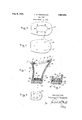
Fig. 1 is a sectional elevation of an assembled heel embodying my invention.
Fig. 2 is a fragment showing the top lift as initially applied to the heel body.
Fig. 3 is a plan looking in the direction of arrow, Fig. 1. Y
Fig. 4 is a plan of the heel from above.
Fig. 5 is a face view of a template which I propose to use with the heels to enable drilling the heel seat of the shoe to facilitate positioning and attaching the heel body. v
Referring to the drawing, the hollow heel body or core 10, is incased by a Wall of ebonite, bakelite or the like, molded to the metal core to form an integral member. at 13 about the contour and the wall is overthe lapped as at 14 to present a uniform surface to' skilled workman, and similarly the Whole heel The heel seat 12 is recessed of a template 118, the holes 15 therethrough, corresponding with the tapped holes in the body element. By this means, `the heel may be positioned by meansof. the template, the holes drilled through the shoe sole, and the heel body attached by means of the screws 16,3 a smooth surfacebeing retained on the inside of the shoe.
The opposite end of the heel body is formed with a ledge 19 surrounding a socket 20, and the major wall of the socket is provided with tapped hole which may be engaged by other screws 22, which -pass through the top lift 23.
This element -is molded from the usual material used for rubber heels, but is formed to present a convex wearing surface 24, and a corresponding beveled shelf 25, surrounding a projecting Vplug 27, the shelf being adapted to engage the ledge of the heel body, when initially applied, linearlynear the outline of the ledge as at 2.6.V Ihe plug 27 is formed to substantially fit the socket in the heel body peripherally, but is of less projection than the depth of the socket.
When the top lift is drawn by the screws 22 against the ledge V19, the projecting plug serves not only to reinforce the top liftwhere unsupported by the ledge 19, and thus provide a more resilient heel tread, but it also permits the fastening screws 22 to be sunk deeper in the lift, increasing `the possible wear of the top lift before replacing, and retaining Athe screws and heads in unmarred condition and usable when the lift is replaced. As the screws are tightened, they draw the top lift'A to exert a yielding tension on the outline as it is drawn against the ledge of the heel body, and thus a tight joint is maintained between the lift and the heel body as at' 28, while preserving a highly resilient heel tread.4 In Fig. 2, the. toplift is shown in its molded form as initially v f applied to the heel body before attaching, and Fig. 1 shows the lift as attached in wearing posig tion.
It will be evident that the top lift may be replaced with facility and withoutthe aid Vof a may be replaced if desired, in both cases using the original screws. i f. l
Havingthusdescribed my invention, I claimt.-
1. In a shoe heel, the combination of a body element one end of which isattachable to ashoe and having a socket'formed in its opposite end surrounded by'aledge having avplane surface; means for attaching the body to the shoe; la top lift of resilient material kmolded with a convex wearing surface; and an opposite shelf surface adapted to engage initially with the socketed endy no' near the outline of the ledge, said top lift being provided with a projection adapted to engage 4pev ripherally with the socket and of less height than the depth of the socket; and means for attaching the lift` tothe body element to present a substantially plane Wearing surface and to engage the opposite shelf surface with the entire surface of the ledge on the heel body.
2. In a shoe heel, the combination of body element one end of which is adapted to be secured detachably to a shoe; the opposite end of the element being formed with a socket surrounded by a ledge having a plane surface; a top lift of resilient material, molded with a` convex Wearing surface and an opposite surface formed with a projection adapted to engage peripherally with the socketl and of less height than the depth thereof, and a surrounding shelf adapted to engage initially with the ledge surface of the body element, linearly near the outline thereof; and
`0f the heel body, outside the socket and linearly means for detachably securing the lift to the body element to present a substantially plane wearing surface, and to engage the entire shelf surface with the ledge surface of the heel body.
3. In a shoe heel having a body element one end of which is attachable to a shoe, and formed.
on its opposite end with a socket surrounded by a ledge having a plane surface, a top lift of resilient material, molded with a convex Wearing surface and an opposite surface formed with a projection adapted to engage peripherally with the socket in the body element, and of less height than the depth thereof, and having a surround- `ing shelf adapted to engage initially with the ledge surface of the body element, linearly near the outline thereof, and adapted to be secured to the body element to engage the entire shelf of the top lift with the ledge of the heel body, to present a substantially plane Wearing surface.
THEOLOGUE` G. DUsoPoLos.
Priority Applications (1)
| Application Number | Priority Date | Filing Date | Title |
|---|---|---|---|
| US606204A US1921663A (en) | 1932-04-19 | 1932-04-19 | Shoe heel |
Applications Claiming Priority (1)
| Application Number | Priority Date | Filing Date | Title |
|---|---|---|---|
| US606204A US1921663A (en) | 1932-04-19 | 1932-04-19 | Shoe heel |
Publications (1)
| Publication Number | Publication Date |
|---|---|
| US1921663A true US1921663A (en) | 1933-08-08 |
Family
ID=24427002
Family Applications (1)
| Application Number | Title | Priority Date | Filing Date |
|---|---|---|---|
| US606204A Expired - Lifetime US1921663A (en) | 1932-04-19 | 1932-04-19 | Shoe heel |
Country Status (1)
| Country | Link |
|---|---|
| US (1) | US1921663A (en) |
-
1932
- 1932-04-19 US US606204A patent/US1921663A/en not_active Expired - Lifetime
Similar Documents
| Publication | Publication Date | Title |
|---|---|---|
| US1936729A (en) | Shoe sole | |
| US1507844A (en) | Tread for boots or shoes | |
| US2233250A (en) | Shoe heel | |
| US1921663A (en) | Shoe heel | |
| US2456659A (en) | Laminated midsole and outsole construction | |
| US2040001A (en) | Sole patch | |
| US1658170A (en) | Shoe bottom | |
| US2464251A (en) | Rubber heel | |
| US1458257A (en) | Rubber heel | |
| US2375153A (en) | Cushion heel | |
| US1715588A (en) | Heel-attaching means for boots and shoes | |
| US1952330A (en) | Heel | |
| GB229884A (en) | Improvements relating to resilient heels | |
| US1545966A (en) | Shoe heel | |
| US1418188A (en) | Boot or shoe | |
| US1436696A (en) | Shoe | |
| US1892596A (en) | Footwear | |
| US2023441A (en) | Shoe heel | |
| US1397834A (en) | Detachable rubber heel for shoes | |
| US1245847A (en) | Oversole. | |
| US1350216A (en) | Shoe-heel | |
| USD83639S (en) | Design for a shoe heel | |
| US1296044A (en) | Wooden-bottomed shoe. | |
| US944287A (en) | Interchangeable rubber heel. | |
| US1363643A (en) | Shoe-heel and attachment therefor |