US1908899A - Vehicle for the collection of and the compressing of refuse and the like - Google Patents
Vehicle for the collection of and the compressing of refuse and the like Download PDFInfo
- Publication number
- US1908899A US1908899A US644900A US64490032A US1908899A US 1908899 A US1908899 A US 1908899A US 644900 A US644900 A US 644900A US 64490032 A US64490032 A US 64490032A US 1908899 A US1908899 A US 1908899A
- Authority
- US
- United States
- Prior art keywords
- tank
- refuse
- vehicle
- compressing
- rod
- Prior art date
- Legal status (The legal status is an assumption and is not a legal conclusion. Google has not performed a legal analysis and makes no representation as to the accuracy of the status listed.)
- Expired - Lifetime
Links
- 238000007599 discharging Methods 0.000 description 2
- 229920000742 Cotton Polymers 0.000 description 1
- 102100034742 Rotatin Human genes 0.000 description 1
- 101710200213 Rotatin Proteins 0.000 description 1
- 238000009825 accumulation Methods 0.000 description 1
- 238000010276 construction Methods 0.000 description 1
- 238000007790 scraping Methods 0.000 description 1
Images


Classifications
-
- B—PERFORMING OPERATIONS; TRANSPORTING
- B65—CONVEYING; PACKING; STORING; HANDLING THIN OR FILAMENTARY MATERIAL
- B65F—GATHERING OR REMOVAL OF DOMESTIC OR LIKE REFUSE
- B65F3/00—Vehicles particularly adapted for collecting refuse
- B65F3/24—Vehicles particularly adapted for collecting refuse with devices for unloading the tank of a refuse vehicle
- B65F3/28—Vehicles particularly adapted for collecting refuse with devices for unloading the tank of a refuse vehicle by a lengthwise movement of a wall, e.g. a plate, a piston, or the like
-
- B—PERFORMING OPERATIONS; TRANSPORTING
- B65—CONVEYING; PACKING; STORING; HANDLING THIN OR FILAMENTARY MATERIAL
- B65F—GATHERING OR REMOVAL OF DOMESTIC OR LIKE REFUSE
- B65F3/00—Vehicles particularly adapted for collecting refuse
- B65F3/14—Vehicles particularly adapted for collecting refuse with devices for charging, distributing or compressing refuse in the interior of the tank of a refuse vehicle
- B65F3/22—Vehicles particularly adapted for collecting refuse with devices for charging, distributing or compressing refuse in the interior of the tank of a refuse vehicle with screw conveyors, rotary tanks
Definitions
- This invention relates broadly to wagon body constructions and has as its object the provision of an improved vehicle for collectmg, transporting, compressing and discharging garbage and like refuse, although in actual practice it will be found that thevehicle can be as well used for collecting cotton in the field and for numerous other purposes as will readily present themselves. 19
- the invention together with its numerous objects and advantages will be best understood from a study of the following description, taken in connection with the accompanying drawings wherein:
- FIG. 1 is a side elevational view of a vehicle embodying the features of the present invention, I
- Figure 2 is a longitudinal sectional view 2 through the vehicle body, the parts being charging refuse from the vehicle.
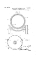
- Figure 3 is a transverse sectional view taken substantially on the line 3 -3 of Fig-' ure 1.
- Figure 4 is a transverse sectional view through the main tank part of the wagon body-and V
- Figure 5 is a sectional elevational view of a follower or plunger mechanism for use in compressing the contents of the wagon and for discharging such contents from sald wagonbody.
- Wagon body '12 comprises a cylindrical shown in the position occupied when dis-.
- the wagon body 12 further comprises a second section or secondar tank 19 that telescopes the rear end of t e tank 13 as shown in' Figure 2.
- the tank '19 is mounted for rotation about the tank 13as an axis, and at the rear end thereof the tank 19 is provided with a closure head 20. At its 0 en forward end tank 19 is provided wit .an inwardly directed annular flange 21 engaging an annular external flange 22 on the tank 13. Intermediate its ends the tank .19 is provided with anvinternallug 23 engaging the rear end edge ofqtank 13.
- a shaft 25 journalled in suitable bearings 26 provided on the chassis frame of the truck 10.
- the shaft 25 has a suitable drive connection with the power take off of the motor of the truck and such drive connection includes a suitable clutch 27 that can be readily operated from the drive seat through'the medium of a control lever 28.
- a pinion 29 At the rear end thereof there is suitably provided on the shaft 25 a pinion 29 that is in mesh with an external ring gear 30 provided on the tank 19 intermediate the ends of the tank.
- a suitably mounted idler gear 31 arranged opposite to the ear 29 as shown in Figure 3.
- Said means consist of a plunger 32 arranged to reci rocate within the tank 13 and provided on its periphery with a ring 33 that has a close fit with the interior wallof V the tank 13 for scraping the same free of any refuse having a tendency to cling thereto.
- the plunger 32 is mounted on one end of a collapsible rod 34.
- Rod 34' consists of a plurality of telescoping sections 35, and each of the sections is provided at one end with an inwardly directed flan e 36, and at an inner end with an exterior gauge 37.
- each section '35 Disposed about each section '35 is a coil spring 38 which at one end impinges against a flange 36 of an outer section, an at a relatively opposite end impinges against. a flan e 37 of the section about which the particufiir spring is disposed (see Figure 5).
- the springs 38 serve to normally urge the sections inwardly relative “to one another or in other words to yieldably retain the rod 34 collapsed.
- the piston or lunger 32 is arranged on the outer and 0 one end section 35, while the section 35 which is of the largest diameter and is arranged at the other end of the rod 34 is slidably engaged within a cylindrical casing 39 that is suitably mounted within the cabin 11 of the truck as suggested .b broken lines in Figure 1.
- the rear end 0 the casing 39. extends through a flange opening 40 provided in the head 14 of tank 13 as shown in Figure 2.
- a spring corresponding to the aforementioned springs 38 is also provided on the inner end of the said end section 35 of the rod for normally urging said end section inwardly extendin with respect to the casing '39.
- Preferabl oil under pressure is used for e rod 34 and to this end, there is provi ed a suitable source of oil supply together with a suitable pum having suit 7 able drive connection with tie power take valve 42 also indicated by broken piston 32 forwardl with respect to t e fillmg 0 ning 15. he tank 19 is also positione as to have the opening 24 disposed u wardly as shown in Flg'ure 1.
- valve 42 is opened whereby oil is "forced into the casing 39 to extend the rod 34 sufiiciently to move the piston or plunger 32 rearwardly for forcing the contents of the tank .13 rearwardly with respect to the filling openings 15 after which the valve 42 is properly manipulated whereby the sup 1y of oil is shut off, andas the rod 34 co lapses under.
- lever 28 When it is desired to discharge the contents of the wagon body 12, lever 28 is properly manipulated for engaging clutch 27 to drive shaft 25 and the tank 19, the tank rotating about the tank 13' from a osition shown in Fi ure 1 to "the position 5 own in Figure 2. Vith the opening 24 now disposed at the bottom of the truck body, an
- rod 34 for shifting the plunger 32 rearwardly will of course force the refuse to the rear of the truck body 12 where it will discharge through the opening 24.
- rod 34 is retracted, and tank 19 revo ved, moving from the position shown in Figure 2 to its normal position, or to the position shown in Figure 4. The truck is then ready for another complete loading.
- Adjacent its lower edge lunger or piston 32 has extending there rom a bracket 43 in-which is journalled a roller 44 that is ridable along the bottom of the tank 13 and fications an this latter arrangement aids in sustaining the weight of the plunger or piston 32.
- a fixed tank a revoluble tank mounted on the fixed tank for rotation about the latter as an axis, said fixed tank being provided with a lateral charging openin and said revoluble tank being provided wit a lateral discharge opening, a plunger mounted to reciprocate in said fixed tank, means for reciprocatin said plunger, and
- a relatively fixed tank provided with chargin openings a revoluble member on one on of the tank substantially closing the latter, said revoluble member being provided with a lateral discharge opening, means for revolving said member, a plunger mounted to reciprocate within said tank, an extensible rod connected with said plun ger, and means for extending and contracting said rod to reciprocate said plunger.
- a relatively fixed cylindrical member a revoluble cylindrical member mounted on said fixed member to rotate about the fixed member as an axis, each of said members being provided with a lateral a erture, inter-engaging means' on said fixe member and on said revoluble member to restrain the latter a ainst longitudinal movement, and a gunger mounted for reciprocation in said xed cylindrical member.
Landscapes
- Engineering & Computer Science (AREA)
- Mechanical Engineering (AREA)
- Refuse-Collection Vehicles (AREA)
Description
kls:
3 Sheets-Sheet l L. F. KAYEL Filed Nov 29,
VEHICLE FOR THE COLLECTION ANDTHE COMPRESSING OF REFUSE AND THE LI May 16, 1933;
Invcnlor fltlorney |lll May 16, 1933. L. F. KAYEL 1,908,899
VEHICLE. FOR THE COLLECTION OF AND THE COMPRESSING OF REFUSE AND THE LIKE.
Filed Nov. 29, 1932 a Sheets-Sheet 2 ll/Il/ Inventor May 16, 1933. F. K L 1,908,899
VEHICLE FOR THE COLLECTION OF AND THE COMPRESSING OF REFUSE AND THE LIKE Filed Nov. 29, 1932 3 Sheets-Sheet 3 Inventor I. FjZ'i je/ llomey Patented May 16, 1933 UNITED s'rAss PATIENT OFFICE;
Lewis 1'. xnYnL, or nonrn nnursrnan, mew You I vnnrcnn ron was common orann ran coirrnnssme or music AND um um:
Applioatlonflled November 29, 1982. Serial No. 644,800.
This invention relates broadly to wagon body constructions and has as its object the provision of an improved vehicle for collectmg, transporting, compressing and discharging garbage and like refuse, although in actual practice it will be found that thevehicle can be as well used for collecting cotton in the field and for numerous other purposes as will readily present themselves. 19 The invention together with its numerous objects and advantages will be best understood from a study of the following description, taken in connection with the accompanying drawings wherein:
Figure 1 is a side elevational view of a vehicle embodying the features of the present invention, I
Figure 2 is a longitudinal sectional view 2 through the vehicle body, the parts being charging refuse from the vehicle.
Figure 3 is a transverse sectional view taken substantially on the line 3 -3 of Fig-' ure 1. v
Figure 4 is a transverse sectional view through the main tank part of the wagon body-and V Figure 5 is a sectional elevational view of a follower or plunger mechanism for use in compressing the contents of the wagon and for discharging such contents from sald wagonbody.
. Referring to the drawings by reference numerals it will be seen, from a study of Figure 1, that I, in carrying out the inven-' tion, make use of a truck, motor'driven, the same being preferably a front wheel drive truck of existin type and designated'generally by the re erence character 10. Smce, other than above mentioned, the particular type of truck is not of the essence of the invention, it is thought that a detail description thereof is unnecessary.
In carrying out the invention there is suitably supported on the chassis frame of the truck rearwardly of the cabin 11 m. im-
proved wagon body, the same being esig-.
nated generally by the' reference character 12. v.
' Wagon body '12 comprises a cylindrical shown in the position occupied when dis-.
' flanges 21, 22 and lug 23 tank 19 is restrained tank 13 of suitable ca acity fixedl mounted on the truck10, and ing provi ed, at the front end thereof with a conventional head 14. The rear end of. the tank 13 is open. as will be clear from a study of Figure 2. Ad'acent its front end, the tank 13 on either or 0th sidesthereof is provided with a filling openin 15 and for the openings 15 are provided oors 16 hinged at their lower edges as at 17. Suitable closure fasteners 18 are provided for releasabl securing the doors 16 in closed condition see Figure 4). The wagon body 12 further comprises a second section or secondar tank 19 that telescopes the rear end of t e tank 13 as shown in'Figure 2. The tank '19 is mounted for rotation about the tank 13as an axis, and at the rear end thereof the tank 19 is provided with a closure head 20. At its 0 en forward end tank 19 is provided wit .an inwardly directed annular flange 21 engaging an annular external flange 22 on the tank 13. Intermediate its ends the tank .19 is provided with anvinternallug 23 engaging the rear end edge ofqtank 13. By reason of against longitudinal shifting movement relative to tank 13' but can be easily rotated about tank'13.
Ad'acent its rear end the tank=19 in the perip eral wall thereof is rovided with a discharge opening 24 an normally, the opening 24 is disposed at the top of the wagon body as shown in Figure 1. To discharge refuse from the wagon body tank 19 is rotated in a manner to be hereinafter set out for lacing the o ning 24 at the botth ed;
tom of e wagon b as shown in Figure 2. For revolving the vtank 19 there is provided a shaft 25 journalled in suitable bearings 26 provided on the chassis frame of the truck 10. At one end thereof the shaft 25 has a suitable drive connection with the power take off of the motor of the truck and such drive connection includes a suitable clutch 27 that can be readily operated from the drive seat through'the medium of a control lever 28. At the rear end thereof there is suitably provided on the shaft 25 a pinion 29 that is in mesh with an external ring gear 30 provided on the tank 19 intermediate the ends of the tank. Also in mesh with the ring gear 30 is a suitably mounted idler gear 31 arranged opposite to the ear 29 as shown in Figure 3. Obviously w an clutch 27 is engaged, by proper manipulationof lever 28ldrive is transmitted to the shaft 25 and and away from the openin s 1'5so as not to interfere with subsequent lling operations and also to force the refuse in the tank 13 toward the rear thereof and through the 0 ning 24, when the parts are in the posit1on shown in Figure 2. Said means, in the present instance, consist of a plunger 32 arranged to reci rocate within the tank 13 and provided on its periphery with a ring 33 that has a close fit with the interior wallof V the tank 13 for scraping the same free of any refuse having a tendency to cling thereto. The plunger 32 is mounted on one end of a collapsible rod 34. Rod 34'consists of a plurality of telescoping sections 35, and each of the sections is provided at one end with an inwardly directed flan e 36, and at an inner end with an exterior gauge 37.
Disposed about each section '35 is a coil spring 38 which at one end impinges against a flange 36 of an outer section, an at a relatively opposite end impinges against. a flan e 37 of the section about which the particufiir spring is disposed (see Figure 5).
The springs 38 serve to normally urge the sections inwardly relative "to one another or in other words to yieldably retain the rod 34 collapsed. As shown, and as is of course understood, the piston or lunger 32 is arranged on the outer and 0 one end section 35, while the section 35 which is of the largest diameter and is arranged at the other end of the rod 34 is slidably engaged within a cylindrical casing 39 that is suitably mounted within the cabin 11 of the truck as suggested .b broken lines in Figure 1. The rear end 0 the casing 39. extends through a flange opening 40 provided in the head 14 of tank 13 as shown in Figure 2. A spring corresponding to the aforementioned springs 38 is also provided on the inner end of the said end section 35 of the rod for normally urging said end section inwardly extendin with respect to the casing '39.
Preferabl oil under pressure is used for e rod 34 and to this end, there is provi ed a suitable source of oil supply together with a suitable pum having suit 7 able drive connection with tie power take valve 42 also indicated by broken piston 32 forwardl with respect to t e fillmg 0 ning 15. he tank 19 is also positione as to have the opening 24 disposed u wardly as shown in Flg'ure 1. Each time t e garbage or refuse is placed in the tank 13 throug one of the openings 15, valve 42 is opened whereby oil is "forced into the casing 39 to extend the rod 34 sufiiciently to move the piston or plunger 32 rearwardly for forcing the contents of the tank .13 rearwardly with respect to the filling openings 15 after which the valve 42 is properly manipulated whereby the sup 1y of oil is shut off, andas the rod 34 co lapses under.
action of springs 38 therebyv retracting the piston 32 so thatrthe latter is again posi tioned forwardly with res ect to the openings 15 the oil is force from the rod through the valve to return either to the source of oil supply or to a reservoir (not shown) and as may be found desirable. 'The operation is again repeated after there has been a sufiicient accumulation of garbage near the doors 15. It will thus be seen that by reason of the operation above mentioned, the portion of the tank around the openings 15 can be maintained clear, and the filling of the tank to its capacity easily accomplished. v
When it is desired to discharge the contents of the wagon body 12, lever 28 is properly manipulated for engaging clutch 27 to drive shaft 25 and the tank 19, the tank rotating about the tank 13' from a osition shown in Fi ure 1 to "the position 5 own in Figure 2. Vith the opening 24 now disposed at the bottom of the truck body, an
extension of rod 34 for shifting the plunger 32 rearwardly will of course force the refuse to the rear of the truck body 12 where it will discharge through the opening 24. 'When the contents of the truck have been fully dischar ed, rod 34 is retracted, and tank 19 revo ved, moving from the position shown in Figure 2 to its normal position, or to the position shown in Figure 4. The truck is then ready for another complete loading.
Adjacent its lower edge lunger or piston 32 has extending there rom a bracket 43 in-which is journalled a roller 44 that is ridable along the bottom of the tank 13 and fications an this latter arrangement aids in sustaining the weight of the plunger or piston 32.,
,Even though I have herein shown and preferred embodiment of the described the invention, it is to be understood that the same is susce tible of further changes, modithe scope of the appended claims.
Having thus descrlbed my invention, what I claim as new is:
1. In a power driven vehicle for collecting refuse, a fixed tank, a revoluble tank mounted on the fixed tank for rotation about the latter as an axis, said fixed tank being provided with a lateral charging openin and said revoluble tank being provided wit a lateral discharge opening, a plunger mounted to reciprocate in said fixed tank, means for reciprocatin said plunger, and
means for rotatin sai revoluble tank.
2. In a power driven vehicle for collecting refuse, a relatively fixed tank provided with chargin openings a revoluble member on one on of the tank substantially closing the latter, said revoluble member being provided with a lateral discharge opening, means for revolving said member, a plunger mounted to reciprocate within said tank, an extensible rod connected with said plun ger, and means for extending and contracting said rod to reciprocate said plunger.
3. In a device of the character described, a relatively fixed cylindrical member, a revoluble cylindrical member mounted on said fixed member to rotate about the fixed member as an axis, each of said members being provided with a lateral a erture, inter-engaging means' on said fixe member and on said revoluble member to restrain the latter a ainst longitudinal movement, and a gunger mounted for reciprocation in said xed cylindrical member. t In testimony whereof ure.
LEWIS F. KAYEL.
improvements coming within I afiix my signa- H
Priority Applications (1)
| Application Number | Priority Date | Filing Date | Title |
|---|---|---|---|
| US644900A US1908899A (en) | 1932-11-29 | 1932-11-29 | Vehicle for the collection of and the compressing of refuse and the like |
Applications Claiming Priority (1)
| Application Number | Priority Date | Filing Date | Title |
|---|---|---|---|
| US644900A US1908899A (en) | 1932-11-29 | 1932-11-29 | Vehicle for the collection of and the compressing of refuse and the like |
Publications (1)
| Publication Number | Publication Date |
|---|---|
| US1908899A true US1908899A (en) | 1933-05-16 |
Family
ID=24586812
Family Applications (1)
| Application Number | Title | Priority Date | Filing Date |
|---|---|---|---|
| US644900A Expired - Lifetime US1908899A (en) | 1932-11-29 | 1932-11-29 | Vehicle for the collection of and the compressing of refuse and the like |
Country Status (1)
| Country | Link |
|---|---|
| US (1) | US1908899A (en) |
Cited By (18)
| Publication number | Priority date | Publication date | Assignee | Title |
|---|---|---|---|---|
| US2430973A (en) * | 1945-07-16 | 1947-11-18 | Arthur Sicard | Vehicular load carrier and collector |
| US2493236A (en) * | 1945-12-21 | 1950-01-03 | Walker Brothers Wigan Ltd | Hydraulically adjustable vehicle body |
| US2793769A (en) * | 1953-11-06 | 1957-05-28 | Weber Walter Otto | Refuse truck with load packing means |
| US2800234A (en) * | 1955-04-06 | 1957-07-23 | Hercules Galion Prod Inc | Vehicle body with packing and ejector plate means |
| US2867340A (en) * | 1957-10-07 | 1959-01-06 | George R Brownlee | Bale wagons |
| US2889944A (en) * | 1956-07-24 | 1959-06-09 | Jonathan H Clark | Loader |
| US2996202A (en) * | 1956-11-05 | 1961-08-15 | Orlando L Neyland | Refuse collection vehicle |
| US3007589A (en) * | 1956-04-16 | 1961-11-07 | Victor A Galloway | Load compressing and dumping vehicle |
| US3358861A (en) * | 1965-05-20 | 1967-12-19 | Termogestioni Aster S P A | Laundry loading container device for washing machines |
| US3486646A (en) * | 1965-10-19 | 1969-12-30 | Gar Wood Ind Inc | Refuse vehicle |
| US3489302A (en) * | 1967-03-14 | 1970-01-13 | Frank Danzart | Garbage collector truck |
| US4062136A (en) * | 1976-09-27 | 1977-12-13 | Toreq, Inc. | Scraper vehicle |
| US4950122A (en) * | 1986-04-24 | 1990-08-21 | Landsdorff Stig-Ragnar Johann | Improvement in monococque containers |
| US6092973A (en) * | 1999-03-19 | 2000-07-25 | Caterpillar Inc. | Dial-in ejector speed control for articulated trucks and the like having ejector type dump mechanism |
| US20110030213A1 (en) * | 2009-08-07 | 2011-02-10 | Weir Spm, Inc. | Hydraulic installation tool for pump plunger |
| USD748228S1 (en) | 2013-01-31 | 2016-01-26 | S.P.M. Flow Control, Inc. | Valve seat |
| US9822894B2 (en) | 2013-11-26 | 2017-11-21 | S.P.M. Flow Control, Inc. | Valve seats for use in fracturing pumps |
| US10240597B2 (en) | 2012-02-03 | 2019-03-26 | S.P.M. Flow Control, Inc. | Pump assembly including fluid cylinder and tapered valve seats |
-
1932
- 1932-11-29 US US644900A patent/US1908899A/en not_active Expired - Lifetime
Cited By (23)
| Publication number | Priority date | Publication date | Assignee | Title |
|---|---|---|---|---|
| US2430973A (en) * | 1945-07-16 | 1947-11-18 | Arthur Sicard | Vehicular load carrier and collector |
| US2493236A (en) * | 1945-12-21 | 1950-01-03 | Walker Brothers Wigan Ltd | Hydraulically adjustable vehicle body |
| US2793769A (en) * | 1953-11-06 | 1957-05-28 | Weber Walter Otto | Refuse truck with load packing means |
| US2800234A (en) * | 1955-04-06 | 1957-07-23 | Hercules Galion Prod Inc | Vehicle body with packing and ejector plate means |
| US3007589A (en) * | 1956-04-16 | 1961-11-07 | Victor A Galloway | Load compressing and dumping vehicle |
| US2889944A (en) * | 1956-07-24 | 1959-06-09 | Jonathan H Clark | Loader |
| US2996202A (en) * | 1956-11-05 | 1961-08-15 | Orlando L Neyland | Refuse collection vehicle |
| US2867340A (en) * | 1957-10-07 | 1959-01-06 | George R Brownlee | Bale wagons |
| US3358861A (en) * | 1965-05-20 | 1967-12-19 | Termogestioni Aster S P A | Laundry loading container device for washing machines |
| US3486646A (en) * | 1965-10-19 | 1969-12-30 | Gar Wood Ind Inc | Refuse vehicle |
| US3489302A (en) * | 1967-03-14 | 1970-01-13 | Frank Danzart | Garbage collector truck |
| US4062136A (en) * | 1976-09-27 | 1977-12-13 | Toreq, Inc. | Scraper vehicle |
| US4950122A (en) * | 1986-04-24 | 1990-08-21 | Landsdorff Stig-Ragnar Johann | Improvement in monococque containers |
| US6092973A (en) * | 1999-03-19 | 2000-07-25 | Caterpillar Inc. | Dial-in ejector speed control for articulated trucks and the like having ejector type dump mechanism |
| US20110030213A1 (en) * | 2009-08-07 | 2011-02-10 | Weir Spm, Inc. | Hydraulic installation tool for pump plunger |
| US10240597B2 (en) | 2012-02-03 | 2019-03-26 | S.P.M. Flow Control, Inc. | Pump assembly including fluid cylinder and tapered valve seats |
| USD748228S1 (en) | 2013-01-31 | 2016-01-26 | S.P.M. Flow Control, Inc. | Valve seat |
| USD787029S1 (en) | 2013-01-31 | 2017-05-16 | S.P.M. Flow Control, Inc. | Valve seat |
| USD856498S1 (en) | 2013-01-31 | 2019-08-13 | S.P.M. Flow Control, Inc. | Valve seat |
| US9822894B2 (en) | 2013-11-26 | 2017-11-21 | S.P.M. Flow Control, Inc. | Valve seats for use in fracturing pumps |
| US10663071B2 (en) | 2013-11-26 | 2020-05-26 | S.P.M. Flow Control, Inc. | Valve seats for use in fracturing pumps |
| US10753495B2 (en) | 2013-11-26 | 2020-08-25 | S.P.M. Flow Control, Inc. | Valve seats for use in fracturing pumps |
| US11585455B2 (en) | 2013-11-26 | 2023-02-21 | Spm Oil & Gas Inc. | Valve seats for use in fracturing pumps |
Similar Documents
| Publication | Publication Date | Title |
|---|---|---|
| US1908899A (en) | Vehicle for the collection of and the compressing of refuse and the like | |
| US2430973A (en) | Vehicular load carrier and collector | |
| US2166846A (en) | Automatic trailer construction | |
| CN205526068U (en) | Road sweeper moves backward and emptys formula dustbin | |
| CN110239858A (en) | An environmentally friendly trash can that is convenient to dump | |
| US2050806A (en) | Loader for refuse vehicles | |
| US1961587A (en) | Refuse collection vehicle | |
| US2316826A (en) | Garbage dumping body | |
| CN113830463A (en) | Space compression garbage storage box for cleaning property garbage | |
| CN109250372A (en) | A kind of garbage transfer complete set of equipments | |
| US2252608A (en) | Dust cart | |
| CN110668053A (en) | Garbage classification compression transfer trolley | |
| US5176488A (en) | Combination rear loading compactor and recycler | |
| US2509388A (en) | Garbage truck | |
| US1863964A (en) | Rubbish cart | |
| US2793769A (en) | Refuse truck with load packing means | |
| CN210794486U (en) | Garbage classification compression transfer trolley | |
| CN207030126U (en) | A kind of cram packer | |
| US3204789A (en) | Garbage truck | |
| US1911514A (en) | Concrete gun | |
| US1996945A (en) | Self loading vehicle | |
| US1963288A (en) | Device for emptying refuse receptacles | |
| US1831648A (en) | Process for the complete filling and emptying of receptacles, such as dust-carts | |
| CN216036615U (en) | Novel garbage truck | |
| CN220363872U (en) | Medical garbage transfer vehicle |