US1908775A - Stabilizer for floating engine mountings - Google Patents
Stabilizer for floating engine mountings Download PDFInfo
- Publication number
- US1908775A US1908775A US567421A US56742131A US1908775A US 1908775 A US1908775 A US 1908775A US 567421 A US567421 A US 567421A US 56742131 A US56742131 A US 56742131A US 1908775 A US1908775 A US 1908775A
- Authority
- US
- United States
- Prior art keywords
- engine
- stabilizer
- frame
- floating
- engine mountings
- Prior art date
- Legal status (The legal status is an assumption and is not a legal conclusion. Google has not performed a legal analysis and makes no representation as to the accuracy of the status listed.)
- Expired - Lifetime
Links
- 239000003381 stabilizer Substances 0.000 title description 3
- 230000000087 stabilizing effect Effects 0.000 description 7
- 238000010276 construction Methods 0.000 description 3
- 230000010355 oscillation Effects 0.000 description 2
- 238000013016 damping Methods 0.000 description 1
Images
Classifications
-
- B—PERFORMING OPERATIONS; TRANSPORTING
- B60—VEHICLES IN GENERAL
- B60K—ARRANGEMENT OR MOUNTING OF PROPULSION UNITS OR OF TRANSMISSIONS IN VEHICLES; ARRANGEMENT OR MOUNTING OF PLURAL DIVERSE PRIME-MOVERS IN VEHICLES; AUXILIARY DRIVES FOR VEHICLES; INSTRUMENTATION OR DASHBOARDS FOR VEHICLES; ARRANGEMENTS IN CONNECTION WITH COOLING, AIR INTAKE, GAS EXHAUST OR FUEL SUPPLY OF PROPULSION UNITS IN VEHICLES
- B60K5/00—Arrangement or mounting of internal-combustion or jet-propulsion units
- B60K5/12—Arrangement of engine supports
- B60K5/1283—Adjustable supports, e.g. the mounting or the characteristics being adjustable
Definitions
- the present invention relates to engine mountings and embodies, more specifically, an improved stabilizing mechanism for engine mountings of the floating type.
- an object of the invention is to provide a stabilizing device for engines which are supported by floating mountings whereby objectionable vibrations may be eliminated when the engines are running at a slow speed.
- an object of thevinvention is to provide a stabilizing device of the above character which functions in response to the vacuum available in theengine manifold.
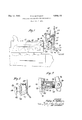
- Figure 1 is a view in side elevation, showing an engine having a stabilizing device constructed in accordance with the present invention.
- Figure 2 is a detail view in section, showing a modified form of stabilizing device.
- Figure 3 is a further modified device constructed in accordance with the present invention. 7
- the engine of a motor vehicle is shown at 10 and the dash board at 11.
- the conventional accelerator pedal 12 is hinged at 13 to the dash and is formed with an arm 1d which preferably engages a link 15 for I valve 16.
- Valve 16 communicates with the intake manifold 17 of the engine through a conduit 18 and a housing 19 is mountedvupon the dash and formed with a suction chamber 20.
- Suction chamber 20 communicates with the valve 16 through the conduit 21 and a piston 22 is adapted to slide in the chamber 20 in response to variations in degree of vacuum within the chamber.
- a rod 23 is connected to a lever 24 through a lost motion connection, the other end of lever 2st being hinged upon a bracket 25 which is carried by the dash.
- a bearing surface 26 may be formed upon the engine to receive a pressure foot 27 which is carried by an arm 28, pivoted upon lever 24 at 29.
- An arcuate finger 3O mounts the pressure foot 27 in juxtaposed relationship with respect to plate 26 and upon a fall in speed of the engine, the suction within the manifold increases and the piston 22 is moved to the left as viewed in Figure 1. Such motion forces the pressure foot 27 against the surface 26 and prevents objectionable vibrations under idling or slow speed conditions of operation of the engine.
- the arm 28 is formed with an axial recess 31 within which a plunger 32 is movable.
- Spring 83 urges the plunger to the left and causes a collar 34 formed thereon to engage a plate 85.
- a tongue 36 is formed on the plunger and is adapted to mate with a slot 37 which is formed in the plate 26. This affords a positive look in place of the friction damping mechanism described above.
- the dash board 11 and bracket 25' carry a lever 38 which is pivoted at 39 to the bracket 25.
- An engine stabilizing device comprising an engine, aframe upon which the engine is mounted, yielding means to mount theengine on the frame, friction means between the engine and frame to resist-relative movement therebetween, an-arm pivoted on the frame and urged away from the frame and toward the engine, and means to mount the friction means on the arm.
- An engine stabilizing device comprising an engine, a frame upon which the engine is mounted, yielding means to mount the engine on the frame, a friction device between the engine and frame, and means to actuate the friction device by'the vacuum in the engine manifold.
- An engine stablhzing device comprlslng an engine, a. frame upon which the engine is mounted, yielding means to mount the engine on the frame, a friction device between the engine and frame, and means to actuate the friction device upon idling of the engine and to render the device inoperative upon a predetermined speed of the engine.
Landscapes
- Engineering & Computer Science (AREA)
- Chemical & Material Sciences (AREA)
- Combustion & Propulsion (AREA)
- Transportation (AREA)
- Mechanical Engineering (AREA)
- Combined Devices Of Dampers And Springs (AREA)
- Arrangement Or Mounting Of Propulsion Units For Vehicles (AREA)
- Vibration Prevention Devices (AREA)
Description
y 3933- P. E. MATTHEW/5% 1,908,?75
STABILIZER FOR FLOATING ENGINE MOUNTINGS Filed Oct. 7, 1931 IN VENT OR BY .5 E.MlZ/Mems; G Q- A KW MS .4270)? 165 Patented May 16, 1933 PAT-En PHILIP E. MATTHEWS, OF PLAINFIELD, NEW JERSEY, ASSIGNOR TO INTERNATIONAL MOTOR COMPANY, OF NEW YORK, N. Y., A CORPORATION OF DELAWARE STABILIZER FOR FLOATING ENGINE MOUNTmGS Application filed. October 7, 1931. Serial No. 567,421.
The present invention relates to engine mountings and embodies, more specifically, an improved stabilizing mechanism for engine mountings of the floating type.
In motor vehicle constructions wherein the engines are mounted upon the vehicle frames with provision for a degree of fioating with respect thereto, it frequently happens that objectionable oscillations of the engine or frame take place when the vehicle is standing still or under specific conditions. These oscillations set up a vibration in the body of the car which is very noticeable and objectionable to the passengers.
It is an object of the present invention, accordingly, to provide an engine mounting of the floating type, wherein the engine vibrations are stabilized by a mechanism which functions under certain specific conditions to eliminate objectionable engine vibration.
More specifically, an object of the invention is to provide a stabilizing device for engines which are supported by floating mountings whereby objectionable vibrations may be eliminated when the engines are running at a slow speed.
More specifically, an object of thevinvention is to provide a stabilizing device of the above character which functions in response to the vacuum available in theengine manifold.
Further objects, not specifically enumerated above, will be apparent as the invention is described in greater detail in connection with the accompanying drawing, wherein:
Figure 1 is a view in side elevation, showing an engine having a stabilizing device constructed in accordance with the present invention.
Figure 2 is a detail view in section, showing a modified form of stabilizing device.
Figure 3 is a further modified device constructed in accordance with the present invention. 7
Referring to the above drawing, the engine of a motor vehicle is shown at 10 and the dash board at 11. The conventional accelerator pedal 12 is hinged at 13 to the dash and is formed with an arm 1d which preferably engages a link 15 for I valve 16.
Valve 16 communicates with the intake manifold 17 of the engine through a conduit 18 and a housing 19 is mountedvupon the dash and formed with a suction chamber 20. Suction chamber 20 communicates with the valve 16 through the conduit 21 and a piston 22 is adapted to slide in the chamber 20 in response to variations in degree of vacuum within the chamber. A rod 23 is connected to a lever 24 through a lost motion connection, the other end of lever 2st being hinged upon a bracket 25 which is carried by the dash.
A bearing surface 26 may be formed upon the engine to receive a pressure foot 27 which is carried by an arm 28, pivoted upon lever 24 at 29. An arcuate finger 3O mounts the pressure foot 27 in juxtaposed relationship with respect to plate 26 and upon a fall in speed of the engine, the suction within the manifold increases and the piston 22 is moved to the left as viewed in Figure 1. Such motion forces the pressure foot 27 against the surface 26 and prevents objectionable vibrations under idling or slow speed conditions of operation of the engine.
In the construction shown in Figure 2, the arm 28 is formed with an axial recess 31 within which a plunger 32 is movable. Spring 83 urges the plunger to the left and causes a collar 34 formed thereon to engage a plate 85. A tongue 36 is formed on the plunger and is adapted to mate with a slot 37 which is formed in the plate 26. This affords a positive look in place of the friction damping mechanism described above.
In the construction shown in Figure 3, the dash board 11 and bracket 25' carry a lever 38 which is pivoted at 39 to the bracket 25.
operating a R A spring only urges the arm 38 outwardly and this arm carries a pressure member 41 to engage the pressure plate 26, thus exerting a continuous force against the pressure surface to prevent vibration of the engine.
While the invention has been described with specific reference to the accompanying drawing, it is not to be limited, save as defined in the appended claims.
I claim as my invention:
1. An engine stabilizing device comprising an engine, aframe upon which the engine is mounted, yielding means to mount theengine on the frame, friction means between the engine and frame to resist-relative movement therebetween, an-arm pivoted on the frame and urged away from the frame and toward the engine, and means to mount the friction means on the arm. 7 I
2. An engine stabilizing device comprising an engine, a frame upon which the engine is mounted, yielding means to mount the engine on the frame, a friction device between the engine and frame, and means to actuate the friction device by'the vacuum in the engine manifold.
3. An engine stablhzing device comprlslng an engine, a. frame upon which the engine is mounted, yielding means to mount the engine on the frame, a friction device between the engine and frame, and means to actuate the friction device upon idling of the engine and to render the device inoperative upon a predetermined speed of the engine.
This specification signed this 10th day of Sept. A. D. 1931.
PHILIP E. MATTHEWS.
Priority Applications (1)
| Application Number | Priority Date | Filing Date | Title |
|---|---|---|---|
| US567421A US1908775A (en) | 1931-10-07 | 1931-10-07 | Stabilizer for floating engine mountings |
Applications Claiming Priority (1)
| Application Number | Priority Date | Filing Date | Title |
|---|---|---|---|
| US567421A US1908775A (en) | 1931-10-07 | 1931-10-07 | Stabilizer for floating engine mountings |
Publications (1)
| Publication Number | Publication Date |
|---|---|
| US1908775A true US1908775A (en) | 1933-05-16 |
Family
ID=24267075
Family Applications (1)
| Application Number | Title | Priority Date | Filing Date |
|---|---|---|---|
| US567421A Expired - Lifetime US1908775A (en) | 1931-10-07 | 1931-10-07 | Stabilizer for floating engine mountings |
Country Status (1)
| Country | Link |
|---|---|
| US (1) | US1908775A (en) |
Cited By (4)
| Publication number | Priority date | Publication date | Assignee | Title |
|---|---|---|---|---|
| FR2465927A1 (en) * | 1979-09-18 | 1981-03-27 | Nissan Motor | VIBRATION ABSORBING SYSTEM FOR USE IN A VEHICLE |
| FR2487740A1 (en) * | 1980-07-30 | 1982-02-05 | Peugeot | Anti-rock guide for transverse vehicle engine - has extensible stop chamber filled with pressurised fluid at idling speeds |
| FR2558913A1 (en) * | 1984-01-28 | 1985-08-02 | Freudenberg Tillmann | MOTOR SUSPENSION BODY |
| FR2653717A1 (en) * | 1989-10-27 | 1991-05-03 | Peugeot | Suspension device for an internal combustion engine, especially the motor vehicle |
-
1931
- 1931-10-07 US US567421A patent/US1908775A/en not_active Expired - Lifetime
Cited By (4)
| Publication number | Priority date | Publication date | Assignee | Title |
|---|---|---|---|---|
| FR2465927A1 (en) * | 1979-09-18 | 1981-03-27 | Nissan Motor | VIBRATION ABSORBING SYSTEM FOR USE IN A VEHICLE |
| FR2487740A1 (en) * | 1980-07-30 | 1982-02-05 | Peugeot | Anti-rock guide for transverse vehicle engine - has extensible stop chamber filled with pressurised fluid at idling speeds |
| FR2558913A1 (en) * | 1984-01-28 | 1985-08-02 | Freudenberg Tillmann | MOTOR SUSPENSION BODY |
| FR2653717A1 (en) * | 1989-10-27 | 1991-05-03 | Peugeot | Suspension device for an internal combustion engine, especially the motor vehicle |
Similar Documents
| Publication | Publication Date | Title |
|---|---|---|
| US1908775A (en) | Stabilizer for floating engine mountings | |
| US2205458A (en) | Carburetor control mechanism | |
| US1996245A (en) | Carburetor | |
| US2250133A (en) | Vehicle signal means | |
| US2575384A (en) | Throttle control for motor vehicle engines | |
| US2281126A (en) | Float valve for carburetors | |
| US2396551A (en) | Switch device | |
| US3646829A (en) | Vehicle accelerator linkage assembly | |
| US2139832A (en) | Governor for internal combustion engines | |
| US3287007A (en) | Throttle control | |
| US2991338A (en) | Vacuum spark advance for ignition systems | |
| US1969682A (en) | Ignition controller | |
| US2869393A (en) | Vehicle accelerator linkage | |
| US2864356A (en) | Ignition distributors | |
| US2308746A (en) | Booster pump and suction switch | |
| US2148305A (en) | Throttle controlling mechanism | |
| US3835826A (en) | Internal combustion engine | |
| US3404246A (en) | Brake switch assembly | |
| US4100893A (en) | Pressure-responsive transducer for regulating internal combustion engine | |
| US4010720A (en) | Accelerator pressure control mechanism | |
| US1980355A (en) | Engine starter control | |
| US2380491A (en) | Switch control mechanism | |
| US2161670A (en) | Clutch chatter eliminator | |
| US2884804A (en) | Transmitting mechanism | |
| US2046730A (en) | Engine starting apparatus |