US1908728A - Electromagnet - Google Patents
Electromagnet Download PDFInfo
- Publication number
- US1908728A US1908728A US454716A US45471630A US1908728A US 1908728 A US1908728 A US 1908728A US 454716 A US454716 A US 454716A US 45471630 A US45471630 A US 45471630A US 1908728 A US1908728 A US 1908728A
- Authority
- US
- United States
- Prior art keywords
- coil
- wires
- cables
- clamping
- connection
- Prior art date
- Legal status (The legal status is an assumption and is not a legal conclusion. Google has not performed a legal analysis and makes no representation as to the accuracy of the status listed.)
- Expired - Lifetime
Links
Images
Classifications
-
- H—ELECTRICITY
- H01—ELECTRIC ELEMENTS
- H01F—MAGNETS; INDUCTANCES; TRANSFORMERS; SELECTION OF MATERIALS FOR THEIR MAGNETIC PROPERTIES
- H01F5/00—Coils
- H01F5/04—Arrangements of electric connections to coils, e.g. leads
Landscapes
- Engineering & Computer Science (AREA)
- Power Engineering (AREA)
- Coils Of Transformers For General Uses (AREA)
Description
y 16, 1933- K BOLLMANN 1,908,728
ELECTROMAGNET Filed May 22, 1950 SW um INVENTOR Patented May 16, 1933 UNITED STATES PATENT OFFICE KARL BOLLMANN', 0F ZURICH, SWITZERLAND, ASSIGNOR TO LANDIS AND GYR, A-G., A CORPORATIGN OF SWITZERLAND ELECTROMAGNET Application filed May 22, 1930, Serial No.
The invention relates to novel and useful improvements in electro-magnets and more especially to such improvements in devices for connecting the ends of fine wire magnet windings, such as those of electricity meters, to the relatively heavy power circuit wires or other outside connections.
Objects and advantages of the invention will be set forth in part hereinafter and in part will be obvious herefrom, the same being realized and attained by means of the instrumentalities and combinations pointed out in the appended claim.
The invention consists in the novel parts, constructions, arrangements, combinations and improvements herein shown and described.
The accompanying drawing, referred to herein and constituting a part hereof, illustrates one embodiment of the invention, and together with the description, serves to explain the principles of the invention.
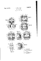
Of the drawing 1- Fig. 1 is an elevation of one embodiment of the invention;
Fig. 2 is a side elevation, looking at Fig. 1 from the left;
Fig. 3 is an elevation of a meter, showing a modified form of the invention;
Figs. 4, 5 and 6 show another modified form of the invention; and
Figs. 7 and 8 likewise show other modified forms of the invention.
While several modified forms of construction embodying the invention are shown in the drawing, it will be understood that such showing is exemplary, and is not restrictive as to the possible number of forms which may be designed While still utilizing the novel principles of the present invention.
The invention in certain of its aspects is especially applicable to electro-magnets which have relatively fine wire windings, such as electricity meter magnets, wherein. the ends of the fine wire for the coils are connected to relatively heavy power line wires or the like.
By my invention coil Wire and line wire connecting means are provided which are immune to breakage of the circuit, or other 454,716, and in Switzerland July 2, 1929.
disturbances, which are simple as to mounting and connection, and inexpensive to manufacture and install. To this end, there is provided a connection between the coil and line wires which is firmly fixed to the extenor of the coil and protects the connection against rupture or damage either by tensional or lateral strains.
Referring now in detail to the various forms shown by way of example in the accompanying drawing, the Figures 1 and 2 show a connection device, which consists in its details of two clamping pieces 1, 2 which take up the pull of the connecting cables, or line wires, and an insulating plate 3 which consists of paper, fiber, or other suitablematerial, carrying the clamping pieces 1, 2. The clamping pieces 1, 2 are passed through apertures 4 in the insulating plate 3 (which apertures are shown in a somewhat similar construction in Figure 5), and are thereby firmly connected therewith. The insulating plate 3 is firmly connected to a coil 8 by any means, such as a band 7, consisting for example of cotton thread. The band 7 passes about the coil 8, and is firmly fixed thereto. The clamps 1 and 2 have two- lateral lugs 5, 6 formed into a channel-shaped eye. The ends of the wires 9, 10 of the bobbin are passed through corresponding openings 11, 12 in the insulating plate 3, and are wound respectively into small wire spirals 13 and 14.
In making the connection, the ends of the cable conductors 15 and 16 are placed within the lugs 5, 6, which are pressed together, whereby the cable conductors are clamped fast, and the free ends 17, -18 of the cables 15, 16 are within the helical ends 13, 14 of the coil wires. A permanent electrical connection is made between the line wire ends 17 18 and the coil wire ends 13, 14, preferably.
by soldering. Thus the ends of the power wires are firmly and simply held on the exterior of the coil, and the ends of the coil wires are fixed thereto, without danger of any strain coming on the connection.
Figure 3 shows a different form of connection. In this form, the ends of the line wire cables 15, 16 are secured against movement relatively to the coil by bending back upon themselves the ends 19, 20 of the clamping pieces 1, 2 (mounted on the insulating plate 3). Eyes 21 and 22 are formed integral with the respective clamping pieces 1', 2. I The ends of the coil wires 9, 10 are passed through eyes 21 and 22, and the ends 17, 18 of the cables 15, 16 are clamped within the turned over ends 19 and 20 of plates 1 and 2; and are connected to ether by soldering. In Figures 4 to 6 t ere is shown a coil with flat connecting conductors, which are used simultaneously for the clamping of the connecting cables. The flat conductors 23, 24 are connected to the inner and outer ends of u the coil winding, and are passed through the holes 4 in the insulating plate 3 (Figure 5) and then brought back again forming loops 25 and 26. The band 7 is wound over and about the bent- back ends 27, 28 of the two a flat conductors 23, 24. After passing the conductor cables 15, 16 through the loops 25, 26, the latter are pressed together, and the ends 27, 28 of the flat conductors 23, 24 soldered to the conducting wires 17 18 of the cables 15,16.
Two simplified constructional forms of connections are shown in Figures 7 and 8, wherein 'onl a single clamping piece 29 is employed. n Figure 7 the clamping of the conductor cables 15, 16 is effected by simply bending around one end 30 of a clamping piece 29, connected to the winding 8 of the coil by a band 7 The other end 31 of the clamping piece 29 is bent around on to the band 7, whereby a more secure hold of the clam 'ng piece 29 on the band 7 is efl'ected. In 1igure 8 the clamping piece'29, which is he by two bands 7, 32, has two lugs 33, 34'clamping the connecting cables 15, 16 laterally. Theconductor ends 17, 18 of the connecting cables 15, 16 and the ends of the bobbin, made in the form of flat conductors 23, 24, are secured together by soldering.
'I'he'invention in its broader aspects is not limited to the s ecific mechanisms shown and described but epartures may be made therefrom within the scope of the accompanying claim Without departing from the principles of. the invention and without sacrificing its chief advantages.
What I claim is 7 An electric coil having a connection with the line circuit includin means for electrically connecting the re atively heav line wires to the relatively fine coil wires, a clampmg device for independentl securing the line wires to the coil so as to ta e any pull thereon, and means for'separately attachin the clamping device to the coil comprising a and embracing the coil and clamping device but lyin between the line wires and said clampmg once, v
n testimony whereof, I have signed my a name to this specification.
I KARL BULLMANN.
Applications Claiming Priority (1)
| Application Number | Priority Date | Filing Date | Title |
|---|---|---|---|
| CH1908728X | 1929-07-02 |
Publications (1)
| Publication Number | Publication Date |
|---|---|
| US1908728A true US1908728A (en) | 1933-05-16 |
Family
ID=4566745
Family Applications (1)
| Application Number | Title | Priority Date | Filing Date |
|---|---|---|---|
| US454716A Expired - Lifetime US1908728A (en) | 1929-07-02 | 1930-05-22 | Electromagnet |
Country Status (1)
| Country | Link |
|---|---|
| US (1) | US1908728A (en) |
Cited By (4)
| Publication number | Priority date | Publication date | Assignee | Title |
|---|---|---|---|---|
| US2478274A (en) * | 1945-03-17 | 1949-08-09 | Ibm | Circuit connecting device |
| US2858514A (en) * | 1953-11-12 | 1958-10-28 | Gen Electric | Insulating and lead anchoring means for transformers |
| US2902661A (en) * | 1954-05-11 | 1959-09-01 | Gen Electric | Coil insulating and lead anchoring means for transformers |
| US3287675A (en) * | 1965-03-01 | 1966-11-22 | Gen Electric | Plug-on electromagnetic relay with an external pocket |
-
1930
- 1930-05-22 US US454716A patent/US1908728A/en not_active Expired - Lifetime
Cited By (4)
| Publication number | Priority date | Publication date | Assignee | Title |
|---|---|---|---|---|
| US2478274A (en) * | 1945-03-17 | 1949-08-09 | Ibm | Circuit connecting device |
| US2858514A (en) * | 1953-11-12 | 1958-10-28 | Gen Electric | Insulating and lead anchoring means for transformers |
| US2902661A (en) * | 1954-05-11 | 1959-09-01 | Gen Electric | Coil insulating and lead anchoring means for transformers |
| US3287675A (en) * | 1965-03-01 | 1966-11-22 | Gen Electric | Plug-on electromagnetic relay with an external pocket |
Similar Documents
| Publication | Publication Date | Title |
|---|---|---|
| US2649558A (en) | Mounting head for coil terminals | |
| US1908728A (en) | Electromagnet | |
| US2150388A (en) | Terminal for electrical devices | |
| US2374018A (en) | Coil winding | |
| US2243553A (en) | Electrical winding | |
| US3553621A (en) | Inductor with terminal carrier | |
| US3321725A (en) | Current transformers having multiturn primary windings | |
| US2200059A (en) | Electrical terminal | |
| KR101684429B1 (en) | Transformer for battery charger | |
| US3622100A (en) | Bobbin with lead strain-relieving device | |
| US2425443A (en) | Coil construction | |
| US2364684A (en) | Method of making vibrators | |
| US708220A (en) | Means for winding converters or like articles. | |
| US2264832A (en) | Coil wrapper | |
| US1301636A (en) | High-voltage-current transformer. | |
| US2043346A (en) | Submarine cable loading coil | |
| GB1529136A (en) | Bobbins for electrical coils | |
| US1998378A (en) | Ignition coil | |
| CN208386086U (en) | Fastening clip for cable | |
| US1718255A (en) | Apparatus for wireless telephony and telegraphy | |
| US1503977A (en) | Winding for electrical apparatus | |
| US1821796A (en) | Winding spool body | |
| GB348770A (en) | Improvements relating to magnet bobbins or coils for electrical apparatus, more especially for meters and other measuring instruments | |
| CN209001537U (en) | Potential device and cable arrangement mechanism | |
| US2436207A (en) | Electric winding |