US1908497A - Electrotype-plate mounting - Google Patents
Electrotype-plate mounting Download PDFInfo
- Publication number
- US1908497A US1908497A US576055A US57605531A US1908497A US 1908497 A US1908497 A US 1908497A US 576055 A US576055 A US 576055A US 57605531 A US57605531 A US 57605531A US 1908497 A US1908497 A US 1908497A
- Authority
- US
- United States
- Prior art keywords
- plate
- aperture
- block
- jaw
- lever
- Prior art date
- Legal status (The legal status is an assumption and is not a legal conclusion. Google has not performed a legal analysis and makes no representation as to the accuracy of the status listed.)
- Expired - Lifetime
Links
Images
Classifications
-
- B—PERFORMING OPERATIONS; TRANSPORTING
- B41—PRINTING; LINING MACHINES; TYPEWRITERS; STAMPS
- B41F—PRINTING MACHINES OR PRESSES
- B41F27/00—Devices for attaching printing elements or formes to supports
- B41F27/04—Devices for attaching printing elements or formes to supports for attaching printing elements to flat type-beds
Definitions
- This invention relates to a mounting for electrotype-plates employed in the printing art.
- Electrotype-plates are thin and composed of soft type metal, which therefore necessitates that they be mounted on a thick base block now in common use in order to bring the printing surface of the plate type high in a fiat bed press.
- the base block is made up of uniform rectangular sections which are clamped in the type bed of the press, although the base block could be integral with the bed as in the case of the rotary type press where the plates are mounted on the cylinder directly.
- One of the objects of the invention is to provide improved means for assuring firmly clamping the plate to the block which also affords expedition of the assembly and dis- 0 assembly thereof.
- Fig. 1 is a plan view of a base block unit of '25 the electrotype-plate mounting embodying the invention.
- Fig. 2 is an edge view of Fig. 1.
- Fig. 3 is an enlarged sectional view taken on the line 33 of Fig. 1.
- Fig. 4 is a sectional view taken on the line H of Fig. 3.
- Fig. 5 is a plan view of Fig. 3.
- Fig. 6 is a bottom view of Fig. 3.
- Fig. 7 is a side view of the plate clamping device.
- Fig. 8 is a side view of Fig. 7.
- Fig. 9 is a sectional view taken on the line 99 of Fig. 7.
- Fig. 10 is a sectional view of a fragment of an arcuate base block embodying a modified form of the invention.
- Fig. 11 is a longitudinal sectional view of a modified form of the clamping device.
- Fig. 12 is a side view of Fig. 11 with parts broken away and parts in section.
- the mounting comprises a rectangularv block 1 having a flat top surface 2 for supporting the electrotype-plate 3.
- the block has vertically disposed inwardly convergent conical apertures 4 closely arranged in rows extending obliquely across the supporting surface and within which are supported in a removable manner the plate clamping or holding devices 5 which are provided about the edges of the plate.
- the block 1 constitutes a unit of which a plurality are assembled edge to edge in longitudinal and transverse rows and clamped within the type bed of a fiat bed press (not shown).' Byreason of the oblique arrangement of the rows of apertures a number of apertures are made accessible about the edge of the plate for the clamping devices regardless ofthe position of theplate.
- the clamping devices 5 comprise an elongated body portion 6 loosely received within an aperture, having a jaw formation 7 extending squarely across its top end and over the aperture.
- the jaw has an upwardly and outwardly inclined plate clamping surface 8 on its side for engaging the beveled edge 9 of the plate.
- the device is oscillatably mounted within the aperture for adjustment by means of the lateral lugs 10 at the bottom of the body porti-on on its jaw face side, which engage the annular shoulderformation 11 formed by the annular recess 12 at the bottom of the aperture.
- the bottom end of the body port-ion of the clamping-device is circular partially cut away at the lugs and is snugly passable through the bottom of the aperture at the shoulder (see Fig. 6) whereby disengagement of the lugs from the shoulder is not easily efiected.
- the body portion of the clamping device between the lugs and the jaw formation is elliptical in cross section with the major axis of the ellipse paralleling the aw surface and gradually increasing in width from bottom to top at the major axis, which forms downwardly converging edges 14 slightly clearing the aperture.
- the width'of the body portion at its minor axis from top to bottom is uniform thus providing parallel opposite side portion 15 which considerably clear the aperture.
- the curvature of the sides of the clamping device conform to the curvature of the aperture, whereupon the clamping device is maintained or confined oscillatable substantially in the jaw facing direction with the maximum amount of adjustability in a plane paralleling the axis of the aperture, also allowing durable construction.
- the jaw formation is thereby maintained in parallelism horizontally with the edge of the plate whereby a firm grip is maintained, although at some adjustments the angles of their engaging faces may vary, in other words the jaw either engages the edge of the plate at its top edge orits'bottom edge depending on its position with, respect to the plate, but its line of contact will be square with the edge of the plate.
- Leverage means is provided on the clamping. device which is operable upon the wall of the aperture for adjusting and holding the awformation in clamping engagement with theedge ofthe plate and holding the lugs 10in engagementwith the shoulder formation'llin the aperture, thus anchoring the device to the block.
- 'Said means comprises a lever 16 in the form of a parallel sided arcuate segment snugly received and oscillatably mounted within the arcuate recess 16 extending along the side of the body portion opposite theljaw facing side, the lever having arcuate guides 17 on both sidesconcentric with the arcuate portion thereof which are-received within the concentric arcuate guideways 18 in the recess of the body.
- the outer surface .19 of the lever is shaped to conform to and be flush with the side of clamping device when the lever is completely received within the recess, whereby no obstruction exists on the side of the device which would otherwise hinder the insertion or removal of the clamping device in an aperture preparatory to clamping the plate tov the block especially when the edge of the plate is so positioned overthe aperture selected as to only permit a very small space for the insertion of the device.
- a worm shaft 20 is provided which is rotatably mounted in the bore 21 extending longitu dinally through the central portion of the body of the clamping device and which in tercepts the arcuate recess 16 at its bottom.
- the worm shaft has meshing engagement with the gear teeth 22 of the lever which are arranged about its axis of oscillation within the-arcuate groove 23 in the arcuate inner side of the lever.
- the bore 21 is reduced at its bottom at 24 within which the reduced end 25 of the shaft takes bearing, and slight- 1y, projects beyond the bore.
- the shaft end has an annular groove 26 within which the split end 27 of a leaf spring 28 is received at the bottom of the body of the device which holds the shaft in the bore 21.
- the worm shaft is rotated by means of a hand tool :29, (shown in dotted lines in Fig. 3) having a squared shank projection 30 which is receivable within the squared bore 31 in the top of the worm shaft.
- the leaf spring 28 projects upwardly from the side of the body of clamping device opposite the lugs 10 and into contact with the wall of the aperture for the purpose of holding the lugs over the shoulder 11 which thereby maintains the clamping device anchored in the aperture when not clamping a plate.
- the function of the spring has no importance when the clamping device is applied to a plate as the lever maintains the jaw in engagement with the plate and the lugs in engagement with the shoulder.
- a recess 32 is provided in the side of the device with? in which the spring is received for preventing its turning out of position and also allowing the device to pass through the bottom of the aperture.
- FIG. 10 A modified form of the invention is illustrated in Fig. 10 comprising a section of a curved block 1 embodying the invention, which makes possible closely arranging the apertures and still maintaining a substantial wall portion therebetweem'because the closer the apertures more apertures are made accessible along the edge of a plate to be clamp.- ed, said embodiment being advantageousin rotary presses.
- a modified form of the clamping device is illustrated in Figs. 11 and 12 withparts similar to the referred form'bein iven similar numerals with prime exponents wherein the positively operated leverage means comprises a lever 33 in the form of a bar which is slidably mounted within the square bore 34 which extends obliquely through the clamping device.
- the bar has gear teeth 35 along the top. which are in mesh with the conical worm gear formation 36 at the end of the shaft 37 which-is rotatably mounted" in the body of the device, and held therein by the pin andgroove connection 38.
- the lever and its operating worm shaft can be made considerably large in proportion to the body of the clamping device without materially weakening it, thus providing a powerfulleverage means in a small clamping device with a minimum amount of elements, which assures firmly clamping the plate to the block;
- a plate holding device comprising an elongated body portion loosely receivable within an aperture and having a laterally directed jaw formation at its top end for engagement with the edge of the plate, a lever mounted on the body portion for movement in a plane paralleling the direction of the jaw and engageable with the wall of the aperture for holding the jaw in engagement with the plate, the lever having gear teeth formations for providing an operable connection and a worm shaft mounted on the body portion in operable connection with the gear teeth of the lever for effecting its movement.
- a plate holding device comprising an elongated body portion loosely receivable within an aperture and having a laterally directed jaw formation at its top for engagement with the edge of a plate, a lever rotatably mounted on the body portion and in cooperative engageable relation with the wall of the aperture for moving the jaw into engagement with the plate and having gear teeth arranged about its axis of rotation, and a worm shaft rotatably mounted in the body portion and in meshing engagement with the teeth of the lever for operating same.
- a mounting for electrotype-plates the combination of a block having a surface for supporting the plate, the block having inwardly convergent conical apertures in its supporting surface which are annularly recessed at the bottoms to provide a shoulder, a plate holding device oscillatably mounted within an aperture, wherein the device comprises an elongated body portion having means for holding the plate on the block, wherein a lateral lug is provided at the bottom of the body portion engaging the shoulder for anchoring the device to the block, the bottom of the body portion including the lug being snugly passable through the bottom of the aperture, and wherein spring means is employed for holding the lug in engagement with the shoulder.
- a plate holding device oscillatably mounted within an aperture, wherein the device comprises an elongated body portion having a laterally directed plate engaging jaw surface formation extending across its top for holding the plate on the block, wherein means are employed for holding the jaw in engagement with the plate, wherein means are employed for anchoring the device at the bottom of the aperture, and wherein the body portion is formed so as to be confined to oscillatable movement substantially in the jaw facing direction.
- a plate holding device comprising an elongated body portion loosely receivable within an aperture and having a laterally directed jaw surface formation extending across its top for engagement with the edge of the plate, the body portion having a longitudinally extended recess in its side opposite the jaw surface side with concentric arcuate guideways in the side walls thereof, a lever element snugly receivable in the recess, having an arcuate guide on each side slidably mounted in the guideways and being engageable with the wall of the aperture for holding the jaw in engagement with the plate, the lever having gear teeth arranged in an arc concentric with the guides and a worm shaft disposed longitudinally in the body portion in meshing engagement with the teeth of the lever for operating it.
Landscapes
- Clamps And Clips (AREA)
Description
May 9, 1933. w WARNOCK 1,908,497
ELEGTROTYPE PLATE MOUNTING Filed Nov. 19, 1931 f wij I? Z9 if? f 7 j 3 nun Patented May 9, 1933 UNITED STATES WALLACE s. WARNOOK, or CHICAGO, ILLINOIS ELECTROTYPE-IPLATE MOUNTING Application filed November 19, 1931. Serial No. 576,055.
This invention relates to a mounting for electrotype-plates employed in the printing art.
Electrotype-plates are thin and composed of soft type metal, which therefore necessitates that they be mounted on a thick base block now in common use in order to bring the printing surface of the plate type high in a fiat bed press. As a rule the base block is made up of uniform rectangular sections which are clamped in the type bed of the press, although the base block could be integral with the bed as in the case of the rotary type press where the plates are mounted on the cylinder directly.
One of the objects of the invention is to provide improved means for assuring firmly clamping the plate to the block which also affords expedition of the assembly and dis- 0 assembly thereof.
Other objects and advantages will become apparent by reference to the specification and accompanying drawing in which:
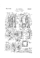
Fig. 1 is a plan view of a base block unit of '25 the electrotype-plate mounting embodying the invention.
Fig. 2 is an edge view of Fig. 1. Fig. 3 is an enlarged sectional view taken on the line 33 of Fig. 1.
Fig. 4 is a sectional view taken on the line H of Fig. 3.
Fig. 5 is a plan view of Fig. 3. Fig. 6 is a bottom view of Fig. 3. Fig. 7 is a side view of the plate clamping device.
Fig. 8 is a side view of Fig. 7. Fig. 9 is a sectional view taken on the line 99 of Fig. 7.
Fig. 10 is a sectional view of a fragment of an arcuate base block embodying a modified form of the invention.
Fig. 11 is a longitudinal sectional view of a modified form of the clamping device.
Fig. 12 is a side view of Fig. 11 with parts broken away and parts in section.
The mounting comprises a rectangularv block 1 having a flat top surface 2 for supporting the electrotype-plate 3. The block has vertically disposed inwardly convergent conical apertures 4 closely arranged in rows extending obliquely across the supporting surface and within which are supported in a removable manner the plate clamping or holding devices 5 which are provided about the edges of the plate. The block 1 constitutes a unit of which a plurality are assembled edge to edge in longitudinal and transverse rows and clamped within the type bed of a fiat bed press (not shown).' Byreason of the oblique arrangement of the rows of apertures a number of apertures are made accessible about the edge of the plate for the clamping devices regardless ofthe position of theplate.
The clamping devices 5 comprise an elongated body portion 6 loosely received within an aperture, having a jaw formation 7 extending squarely across its top end and over the aperture. The jaw has an upwardly and outwardly inclined plate clamping surface 8 on its side for engaging the beveled edge 9 of the plate.
The device is oscillatably mounted within the aperture for adjustment by means of the lateral lugs 10 at the bottom of the body porti-on on its jaw face side, which engage the annular shoulderformation 11 formed by the annular recess 12 at the bottom of the aperture. The bottom end of the body port-ion of the clamping-device is circular partially cut away at the lugs and is snugly passable through the bottom of the aperture at the shoulder (see Fig. 6) whereby disengagement of the lugs from the shoulder is not easily efiected.
The body portion of the clamping device between the lugs and the jaw formation is elliptical in cross section with the major axis of the ellipse paralleling the aw surface and gradually increasing in width from bottom to top at the major axis, which forms downwardly converging edges 14 slightly clearing the aperture. The width'of the body portion at its minor axis from top to bottom is uniform thus providing parallel opposite side portion 15 which considerably clear the aperture. The curvature of the sides of the clamping device conform to the curvature of the aperture, whereupon the clamping device is maintained or confined oscillatable substantially in the jaw facing direction with the maximum amount of adjustability in a plane paralleling the axis of the aperture, also allowing durable construction. The jaw formation is thereby maintained in parallelism horizontally with the edge of the plate whereby a firm grip is maintained, although at some adjustments the angles of their engaging faces may vary, in other words the jaw either engages the edge of the plate at its top edge orits'bottom edge depending on its position with, respect to the plate, but its line of contact will be square with the edge of the plate.
Leverage means is provided on the clamping. device which is operable upon the wall of the aperture for adjusting and holding the awformation in clamping engagement with theedge ofthe plate and holding the lugs 10in engagementwith the shoulder formation'llin the aperture, thus anchoring the device to the block. 'Said means comprises a lever 16 in the form of a parallel sided arcuate segment snugly received and oscillatably mounted within the arcuate recess 16 extending along the side of the body portion opposite theljaw facing side, the lever having arcuate guides 17 on both sidesconcentric with the arcuate portion thereof which are-received within the concentric arcuate guideways 18 in the recess of the body. The outer surface .19 of the lever is shaped to conform to and be flush with the side of clamping device when the lever is completely received within the recess, whereby no obstruction exists on the side of the device which would otherwise hinder the insertion or removal of the clamping device in an aperture preparatory to clamping the plate tov the block especially when the edge of the plate is so positioned overthe aperture selected as to only permit a very small space for the insertion of the device.
The lever 16 is operated in a positive manner for=moving it into contact with the wall of the aperture at its top and withdrawing it into the recess out of contact with the wall, whereby respective. engagement and disengagement of the jaw with the plate is positively effected which expedites the assembling and disassembling operation thereof. For operating the lever in the manner stated, a worm shaft 20 is provided which is rotatably mounted in the bore 21 extending longitu dinally through the central portion of the body of the clamping device and which in tercepts the arcuate recess 16 at its bottom. The worm shaft has meshing engagement with the gear teeth 22 of the lever which are arranged about its axis of oscillation within the-arcuate groove 23 in the arcuate inner side of the lever. The bore 21 is reduced at its bottom at 24 within which the reduced end 25 of the shaft takes bearing, and slight- 1y, projects beyond the bore. The shaft end has an annular groove 26 within which the split end 27 of a leaf spring 28 is received at the bottom of the body of the device which holds the shaft in the bore 21. The worm shaft is rotated by means of a hand tool :29, (shown in dotted lines in Fig. 3) having a squared shank projection 30 which is receivable within the squared bore 31 in the top of the worm shaft. The leaf spring 28 projects upwardly from the side of the body of clamping device opposite the lugs 10 and into contact with the wall of the aperture for the purpose of holding the lugs over the shoulder 11 which thereby maintains the clamping device anchored in the aperture when not clamping a plate. The function of the spring has no importance when the clamping device is applied to a plate as the lever maintains the jaw in engagement with the plate and the lugs in engagement with the shoulder. A recess 32 is provided in the side of the device with? in which the spring is received for preventing its turning out of position and also allowing the device to pass through the bottom of the aperture.
A modified form of the invention is illustrated in Fig. 10 comprising a section of a curved block 1 embodying the invention, which makes possible closely arranging the apertures and still maintaining a substantial wall portion therebetweem'because the closer the apertures more apertures are made accessible along the edge of a plate to be clamp.- ed, said embodiment being advantageousin rotary presses.
A modified form of the clamping device is illustrated in Figs. 11 and 12 withparts similar to the referred form'bein iven similar numerals with prime exponents wherein the positively operated leverage means comprises a lever 33 in the form of a bar which is slidably mounted within the square bore 34 which extends obliquely through the clamping device. The bar has gear teeth 35 along the top. which are in mesh with the conical worm gear formation 36 at the end of the shaft 37 which-is rotatably mounted" in the body of the device, and held therein by the pin andgroove connection 38.
One of the main advantages of the construction of the clamping device of the preferred form, is that, due to the fact it is necessary that they be made very small, as a rule. not being over three-fourths of an inch in length, the lever and its operating worm shaft can be made considerably large in proportion to the body of the clamping device without materially weakening it, thus providing a powerfulleverage means in a small clamping device with a minimum amount of elements, which assures firmly clamping the plate to the block;
Having thus described myinvention, I claim: v
1. The combination with a mounting'for electrotype-plates having a block for supporting the plate with vertically disposed apertures in the supporting surface thereof, of a plate holding device comprising an elongated body portion loosely receivable within an aperture and having a laterally directed jaw formation at its top end for engagement with the edge of the plate, a lever mounted on the body portion for movement in a plane paralleling the direction of the jaw and engageable with the wall of the aperture for holding the jaw in engagement with the plate, the lever having gear teeth formations for providing an operable connection and a worm shaft mounted on the body portion in operable connection with the gear teeth of the lever for effecting its movement.
The combination with a mounting for electrotype-plates having a block for supporting the plate with vertically disposed apertures in the supporting surface thereof, of a plate holding device comprising an elongated body portion loosely receivable within an aperture and having a laterally directed jaw formation at its top for engagement with the edge of a plate, a lever rotatably mounted on the body portion and in cooperative engageable relation with the wall of the aperture for moving the jaw into engagement with the plate and having gear teeth arranged about its axis of rotation, and a worm shaft rotatably mounted in the body portion and in meshing engagement with the teeth of the lever for operating same.
3. The combination with a mounting for electrotype-plates having a block for supporting the plate with a plurality of apertures in its supporting surface which are recessed about their bottoms to form a shoulder, of a plate holding device oscillatably mounted within an aperture, wherein the de vice comprises an elongated body port-ion having means for holding the plate on the block, wherein a lateral lug is provided at the bottom of the body portion engaging the shoulder for anchoring the device to the block, and wherein spring means is employed for holding the lug in engagement with the shoulder.
4:. In a mounting for electrotype-plates the combination of a block having a surface for supporting the plate, the block having inwardly convergent conical apertures in its supporting surface which are annularly recessed at the bottoms to provide a shoulder, a plate holding device oscillatably mounted within an aperture, wherein the device comprises an elongated body portion having means for holding the plate on the block, wherein a lateral lug is provided at the bottom of the body portion engaging the shoulder for anchoring the device to the block, the bottom of the body portion including the lug being snugly passable through the bottom of the aperture, and wherein spring means is employed for holding the lug in engagement with the shoulder.
5. In a mounting for electrotype-plates the combination of a block having a surface for supporting the plate, the block having 1nwardly convergent conical apertures in its supporting surface, a plate holding device oscillatably mounted within an aperture, wherein the device comprises an elongated body portion having a laterally directed plate engaging jaw surface formation extending across its top for holding the plate on the block, wherein means are employed for holding the jaw in engagement with the plate, wherein means are employed for anchoring the device at the bottom of the aperture, and wherein the body portion is formed so as to be confined to oscillatable movement substantially in the jaw facing direction.
6. The structure as claimed in claim 5, wherein the body portion formation is elliptical in cross section with the major axis of the ellipse paralleling the jaw formation, and having downwardly converging edges at the major axis of the ellipse.
7. The combination with a mounting for electrotype-plates having a block for supporting the plate with vertically disposed apertures in the supporting surface thereof, of a plate holding device comprising an elongated body portion loosely receivable within an aperture and having a laterally directed jaw surface formation extending across its top for engagement with the edge of the plate, the body portion having a longitudinally extended recess in its side opposite the jaw surface side with concentric arcuate guideways in the side walls thereof, a lever element snugly receivable in the recess, having an arcuate guide on each side slidably mounted in the guideways and being engageable with the wall of the aperture for holding the jaw in engagement with the plate, the lever having gear teeth arranged in an arc concentric with the guides and a worm shaft disposed longitudinally in the body portion in meshing engagement with the teeth of the lever for operating it.
Signed at Chicago, Illinois, this 16th day of November, 1931.
WALLACE S. WARNOCK.
Priority Applications (1)
| Application Number | Priority Date | Filing Date | Title |
|---|---|---|---|
| US576055A US1908497A (en) | 1931-11-19 | 1931-11-19 | Electrotype-plate mounting |
Applications Claiming Priority (1)
| Application Number | Priority Date | Filing Date | Title |
|---|---|---|---|
| US576055A US1908497A (en) | 1931-11-19 | 1931-11-19 | Electrotype-plate mounting |
Publications (1)
| Publication Number | Publication Date |
|---|---|
| US1908497A true US1908497A (en) | 1933-05-09 |
Family
ID=24302780
Family Applications (1)
| Application Number | Title | Priority Date | Filing Date |
|---|---|---|---|
| US576055A Expired - Lifetime US1908497A (en) | 1931-11-19 | 1931-11-19 | Electrotype-plate mounting |
Country Status (1)
| Country | Link |
|---|---|
| US (1) | US1908497A (en) |
Cited By (2)
| Publication number | Priority date | Publication date | Assignee | Title |
|---|---|---|---|---|
| US2756675A (en) * | 1949-07-08 | 1956-07-31 | Nat Lead Co | Printing plate clamping device |
| US2945284A (en) * | 1957-04-15 | 1960-07-19 | Miehle Goss Dexter Inc | Plate locating mechanism for stereotype plate finishing machine |
-
1931
- 1931-11-19 US US576055A patent/US1908497A/en not_active Expired - Lifetime
Cited By (2)
| Publication number | Priority date | Publication date | Assignee | Title |
|---|---|---|---|---|
| US2756675A (en) * | 1949-07-08 | 1956-07-31 | Nat Lead Co | Printing plate clamping device |
| US2945284A (en) * | 1957-04-15 | 1960-07-19 | Miehle Goss Dexter Inc | Plate locating mechanism for stereotype plate finishing machine |
Similar Documents
| Publication | Publication Date | Title |
|---|---|---|
| US1840685A (en) | Wrench | |
| US1908497A (en) | Electrotype-plate mounting | |
| US3340611A (en) | Bolt cutter having handles interlinked with cam means and gear means | |
| US2149541A (en) | Wrench | |
| US1913392A (en) | Flexible sheet securing means | |
| US2697372A (en) | Slidable jaw insert for crescent head wrenches | |
| US2525363A (en) | Ink fountain for rotary printing presses | |
| US1504870A (en) | Wrench | |
| DE633479C (en) | Device for setting two-part iron pit punches | |
| DE497633C (en) | Brake shoe with removable lining | |
| US568242A (en) | Charles p | |
| US1961797A (en) | Combination clamp and anchor means for the plates of rotary printing presses | |
| US3588976A (en) | Cutter with adjustable clamping blades | |
| US2101173A (en) | Plate clamp | |
| US1500314A (en) | Wrench | |
| US2236805A (en) | Ink fountain conversion device for printing presses | |
| US1718031A (en) | Saw handle | |
| US1601155A (en) | Printing-press plate clamp | |
| US1961442A (en) | Tool holder | |
| US2549226A (en) | Means for holding printing plates to rotary presses | |
| US998447A (en) | Means for holding and adjusting printing-plates on a base-plate. | |
| US1327433A (en) | Violin-bow | |
| US2090259A (en) | Tool | |
| US1526749A (en) | Wrench | |
| US1204894A (en) | Plate-holding device. |