US1908492A - Pneumatic dispatch carrier - Google Patents
Pneumatic dispatch carrier Download PDFInfo
- Publication number
- US1908492A US1908492A US262557A US26255728A US1908492A US 1908492 A US1908492 A US 1908492A US 262557 A US262557 A US 262557A US 26255728 A US26255728 A US 26255728A US 1908492 A US1908492 A US 1908492A
- Authority
- US
- United States
- Prior art keywords
- ring
- carrier
- flange
- characteristic
- index
- Prior art date
- Legal status (The legal status is an assumption and is not a legal conclusion. Google has not performed a legal analysis and makes no representation as to the accuracy of the status listed.)
- Expired - Lifetime
Links
- 238000007373 indentation Methods 0.000 description 5
- 125000006850 spacer group Chemical group 0.000 description 5
- 239000000969 carrier Substances 0.000 description 3
- 238000010276 construction Methods 0.000 description 3
- 239000003086 colorant Substances 0.000 description 2
- 239000002184 metal Substances 0.000 description 2
- 241000726103 Atta Species 0.000 description 1
- 208000027418 Wounds and injury Diseases 0.000 description 1
- 208000027697 autoimmune lymphoproliferative syndrome due to CTLA4 haploinsuffiency Diseases 0.000 description 1
- 230000006378 damage Effects 0.000 description 1
- 208000014674 injury Diseases 0.000 description 1
- 239000000463 material Substances 0.000 description 1
- 230000004048 modification Effects 0.000 description 1
- 238000012986 modification Methods 0.000 description 1
- 230000001012 protector Effects 0.000 description 1
- 238000004080 punching Methods 0.000 description 1
- 230000000717 retained effect Effects 0.000 description 1
Images

Classifications
-
- B—PERFORMING OPERATIONS; TRANSPORTING
- B65—CONVEYING; PACKING; STORING; HANDLING THIN OR FILAMENTARY MATERIAL
- B65G—TRANSPORT OR STORAGE DEVICES, e.g. CONVEYORS FOR LOADING OR TIPPING, SHOP CONVEYOR SYSTEMS OR PNEUMATIC TUBE CONVEYORS
- B65G51/00—Conveying articles through pipes or tubes by fluid flow or pressure; Conveying articles over a flat surface, e.g. the base of a trough, by jets located in the surface
- B65G51/04—Conveying the articles in carriers having a cross-section approximating that of the pipe or tube; Tube mail systems
- B65G51/06—Despatch carriers for tube mail
Definitions
- This invention pertains to pneumatic dispatchsystenis and more particularly to carriers for use in such systems.
- Modern pneumatic systems are'frequently of verycoinplex character comprising many outlying stations and employing many opervvatoi's at the central station designated to perform special functions, so that it .has become desirable to provide thevcarrier With means capable of indicating a greatvarietyof matters Vindependently one of the other.
- VThe usual cash carrier is of standard dimensions devices of usual type.
- iizi'alit of indicator rinO's are mountedat one end of the carrier, and provision is made ⁇ for positively locking the several rings in relatively adjustedrposition, but prior to and after adjustment itis 'necessary to actuate a locking element separate from4 "the-ring, and
- this vcarrier is of that type which opens at one endso that a Vsubstantial portion of its' length is available for the reception of such indicator rings. Hoivever, such a carrier is not adapted for use in transmitting eashor for likepurposes.
- a cash carrier of' I provide an ordinary cash carrier, having heads ateach endand a'largecentral access opening, ,With'a plurality of independently movable index ⁇ devices-so disposed that they Ado not'interfere'with the properoperation of the carrier and do not decrease the Anormal size-of ⁇ the access opening; and for retaining 'such index devices -inproper adjusted pesition I urnishlockingmeans of very simple character adapted effectively and certainly to retain Veach index]deviceindeiinitely in ad- ]usted positiomalthough permitting them to be adjusted independently atfwill merelyby the applicationof"suliicientfforcel PreferabLy I employ colorfcharacteristics in connection With one at least'ofthese vindicator devices, and-by an arrangement liereinafter vdescribed am thus able'to provide for a large number of distinguishing combina- -tioiis'by the use of but a single moving
- Fig. 5 is a plan view of a resilient washer forming a part of the carrier
- Fig. 6 is an enlarged fragmentary section on the line 6-6 of Fig. 5;
- Fig. 7 is a developed edge view of the ring shown in Fig. 3;
- Fig. 8 is a fragmentary developed view of a portion of one end of the body of the carrier.
- Fig. 9 is a fragmentary developed edge view of a second indicator ring
- Fig. 10 is a side elevation of a cash carrier provided with a modified construction of indicator ring;
- Fig. 11 is a view similar to Fig. 2 showing a section of such carrier.
- Fig. 12 is a fragmentary elevation of parts shown in Fig. 11.
- the carrier herein illustrated is of that genera-l type more fully described in the patent to ⁇ Holdsworth No. 1,585,289, May V18, 1926, although the invention is not necessarily limited to embodiment in this particular form of carrier.
- the carrier as herein shown, comprises outer and inner concentric telescoping shells 1 and 2 forming the body of the carrier and the heads 3 and 4 Vsecured to opposite ends of the body.
- the head 3 one of the heads, for example, the head 3,
- the numeral 7 designates the closed end of the outer shell 1.
- the head or bumper 3 is secured to the end member 7 of the shell 1 bymeans of a. pair of rivets or bolts 8.
- a plate 9 is interposed between the inner ends of the rivets 8 and the inner surface of the end 7 of the shell.
- a spacer plate 10 is arranged, such plate having openings for the rivets 8, and above this spacer plate I provide a resilient or spring metal washer 11 constituting one element of the index retaining means as hereinafter more fully described.
- Above lthis resilient plate or washer 11 I provide a spacer plate 12 which underlies the driving washer 6, the bumper or head 3 being disposed in engagement with the upper surface of the washer 6.
- the rivets or bolts 8 hold all of the above parts in rigidly assembled relation.
- I provide a rotary index ring having an inwardly directed radial annular flange 13 of substantially the same thickness as the spacer 10, and.
- Whih. is iat-Grues@ bet-veen outer surface of the end member 7 and the under side of the spring washer 11.
- This index ring also comprises a cylindrical ange 14 which encircles the shell 1 at a point closely adjacent to the head 3, the overhang of the head providing protection for this ring so that the latter is not readily damaged during the use of the carrier.
- the spring plate or washer 11 is preferably provided with one or more, preferably three, ribs, lugs, or bosses 15 conveniently produced by a stamping or punching operation.
- the radial flange 13 of the index ring is provided with a corresponding series of radial sockets or indentations 16 adapted to receive the ribs 15 of the spring washer.
- the ribs or projections may be on the ring and the sockets or indentations in the washer, if desired.
- the outer surface of the cylindrical flange 14 of the index ring is provided with a series of spaced index characteristics, and in Figs. 1 and 7 I have shown such characteristics as consisting of groups of letters of the alphabet. equal distances circumferentially of the flange 14 and are preferably centered on the radial planes of the several sockets 16.
- Upon the outer surface of the outer shell I provide a designating character or mark such, for example, as the arrow 17 adapted to coopcrate with any -of the index characters on the flange 14 to denote that character or group of characters which has been selected.
- the detent ribs 15 are seated in corresponding sockets 16 of the flange 13 and the resiliency of the washer 11 is such as to prevent escape of the detent ribs from the sockets, thus securely holding the index ring in adjusted position.
- the ribs 15 are preferably rounded and the sockets 16 are likewise rounded, it is possible by application of sufficient force to the flange 14 to turn the index ring so as to bring another character or group of characters opposite to the arrow 17.
- the user of the carrier may thus vary the designated characteristic with the greatest ease and without employing tools or manipulating special and unusual elements not commonly found in carriers of this type, while at the same time the index ring is securely retained in the proper position.
- the construction thus provided is of very simple character and adds but little to the cost or weight of the carrier, while it is of durable character and not subject to injury nor liable to fail even after long periods of use.
- this ring is at the opposite endof the carrier, such ring being designated by the numeral '19.
- This ring vis in general of the same construction as These groups are spaced at,-
- the index ring previously described is ⁇ retained upon the end of the carrier inthe Vsaine manner, and is provided with the saine .authorizer to note at once whether. the article purchased is to be taken yaway by the purchaser or is to be sent. llfhen the article is to be taken by the purchaser, it is desirable to have the transaction completed more promptly than when the merchandise is to be sent, and thus I have arranged this second ring 19 so that the dispatching clerk can readily indicate to the authorizer whether the article is to be taken or sent.
- I may provide the surface of the outer shell 1 at one or more points with the word Take suitably marked on or impressed in the metal or shell, and I then provide the ring 19 with a window which may be brought into registry with the word Take or which may be turned awa-y from such word so that the lattei' is concealed.
- this particular index characteristic to wit, the word Take is merely illustrative of any designating characteristic which it kmay be desired to employ and which is -to be rendered visible or alternately to be occulted at the will of the person dispatching the carrier.
- -I may form the ring with a plurality of windows indicated in Fig. 9 at 20, 20a, 20b and 20.
- V may also color the exterior surface of this vring designated as 9a so as to form areas of Vdistinctively different appearances, each of tends along the apertured or windowed space.
- V may also color the exterior surface of this vring designated as 9a so as to form areas of Vdistinctively different appearances, each of tends along the apertured or windowed space.
- the word Take to indicate a certain fact or circumstance or alternately the saine color maybe employed as a blank at the po- -sition of the occulted word Take, thus indicating another fact or circumstance.
- I may provide an -arrow or other mark 21 on the surface of the vcarrier.
- This flange ,14a may be coloredas previously described, but in .this
- .instance such outer surface is protected by means of .a secondary ring, here illustrated .as stationary, comprising a flange 24 overlying the flange 14a', such secondary .ring having, a radial flange .which may if desired be secured in fixed position bymeans of the head ,atta'ching'bolts lor rivets. .Preferably va spacer .25 nia-y be.introducedbetweenrthis .secondary ringandthe Washer 11a. to p-rovide sufficient .space for the movements of the latter. .
- the protector ring 24 is vfurnished with. a window 27. through whichany one of .the lcolored areas lof the ring laamay be exhibited, .and ifi this4 flange has windows,
- the opposite end of theccarrier may be plainor lia-vea rotary ring and is here shown-providedwith a ring 190 having Windows 191 through which the wordFTake lll() Vor other index characteristic is exposed .sim-
- Vteristics can beprovided ⁇ upon this lcarrier and that such combinations can befmade up atthearll .0f ..theiiser,Wit-hout @Specialisti fort and with a minimum expenditure of time and without substantially complicating the carrier, adding to its weight, or cutting down the normal area of the access opening.
- a pneumatic dispatch carrier having a cylindrical body portion and an index ring embracing said body portion and turning relatively thereto, said ring having a flange provided with a plurality of circumferentially spaced indentations therein, and detent means including a spring Washer having a boss engageable with the indentations in the ring and exerting force in an axial direction tending to keep the boss engaged with a selected indentation.
- a pneumatic dispatch carrier having a cylindrical body portion and an index ring embracing said body poition and turning relatively thereto, said ring having a flange, detent element-s on the ring flange, and a spring washer provided with cooperating detent elements, said washer exerting pressure in an axial direction upon the flange thereby normally holding the detent elements thereon in engagement with those on the ring flange.
- a pneumatic dispatch carrier having a cylindrical body portion and an index ring encircling said body portion and rotatable relatively thereto, said-ring having an annular flange extending radially over one end of the body portion, and resilient detent means movable in an axial direction and noi'- mally engaging the flange to retain the ring in selected position said flange having elements thereon with which the detent means engage.
- a carrier for pneumatic dispatch systems comprising a cylindrical body portion and a rotatable ring encircling said body portion, said ring comprising a radially extending annular flange and arcylindrical flange, and a resilient plate engaging the radial flange, said plate and flange having cooperating detent elements normally operative to retain the ring in selected position, said detent elements slipping to permit rotation of the ring when sufficient rotative force is applied to the latter.
- a carrier for pneumatic dispatch systems comprising a cylindrical body portion and a rotatable ring encircling said body portion adjacent one end thereof, said ring comprising an annular flange extending radially over that end of the body portion and a cylindrical flange, a resilient plate engaging the radial flange, the plate having a detent tooth and the radial flange having a socket engageable by the tooth for retaining the ring in selected position.
- a carrier ofthe class described comprising a cylindrical body and a bumper or r head at the end of the body, a rotatable ring encircling the body at a point adjacent to the head, said iing comprising a cylindrical flange having a series of distinctive index characteristics upon its outer surface and av radial annular flange having a series of sockets therein and interposed between the end of the body and the bumper or head, and a resilient washer interposed between the bumper and said radial flange, the washer having a detent tooth engageable with any of a series of sockets in said radial flange, the sockets corresponding in number and spacing with the series of index character'- istics on the cylindrical flange.
- a carrier of the class described comprising a cylindrical body and a head secured to the end of the body, a rotatable ring encircling the body at a point adjacent to the head, said ring having a cylindrical flange provided with a window opening and a radial annular flange interposed between the body and head, a resilient Washer between the head and said radial flange, the flange and washer having cooperating detent elements axially movable and 'normally operative to hold the ring in selected position, but permitting it to rotate when subjected to suliicient rotative force, and designating characteristics upon the outer surface of the body beneath the cylindrical flange of the rotary ring.
- a carrier of the class described comprising a body provided with a head at each end and an access opening in its side wall intermediate tlie heads, a rotary ring encircling said body, saidV ring having a series of windows therein separated by'blank spaces, the body having a distinguishing index characteristic visible through any selected one of said windows when the ring is properly positioned, but invisible when the ring is turned to an intermediate position, and series of differently colored areas upon the i'ing, there being one area of each color corresponding to each window whereby the color of the area through which the characteristic is visible may be determined bythe window selected to register therewith.
- a pneumatic dispatch carrier comprising a cylindrical body portion having thereon an index characteristic, a relatively inevable ring surrounding the body portion over said characteristic. and having a window therein through which such characteristic may be exposed and a stationary Ting SUF- rounding said movable ring and having a window therein registering with said characteristic, whereby the characteristic will be visible when the window in the stationary ring coincides with the window in the movable ring.
- a pneumatic dispatch carrier comprising a cylindrical body portion having thereon an index characteristic, a relatively movable ring surrounding the body portion over said characteristic, and having a seri-es of windows therein through any of which the characteristic on the body portion may be exposed, the surface of the ring at each window being treated, and a second ring surrounding said first ring and having a window therein larger than the windows of the first ring and adapted to register with said characteristic wherebywhen the windows in the two rings register th-e characteristicv on the body portion and the treated surface at the window of the first ring may be visible.
- a pneumatic dispatch carrier comprising a cylindrical body portion having thereon an index characteristic, a relatively movable ring surrounding the body portion over said characteristic, and having a series of windows therein through any of which the characteristic on the body portion may be exposed, the surface of the ring at each window being provided with color which contrasts with the color at the other windows, and a second ring surrounding said first ring and having a window therein larger than the windows of the first ring and adapted to register with said characteristic whereby when windows in the two rings register, the characteristic on the body portion and the color at the selected window of the first ring may be visible.
- a pneumatic dispatch carrier comprising a cylindrical body portion having thereon an index characteristic, a relatively movable ring surrounding the body portion over said characteristic, and having a series of windows therein through any of' which the characteristic on the body portion may be exposed, the surfaces of said ring between the windows being treated, and a stationary ring surrounding said first ring and having a window therein which registers with the characteristic whereby when windows in the two rings coincide, the characteristic on the body portion will be visible and when the windows do not coincide one of the treated surfaces of the first ring will be visible.
- a pneumatic dispatch carrier comprising a cylindrical body portion having thereon an index characteristic, a relatively movable ring surrounding the body portion over said characteristic, and having a series of windows therein through any of which the characteristic on the body portion may be exposed, the surfaces of the ring at each window being provided with color which contrasts with the color at the other windows, and the surfaces of the ring between the windows being similarly provided with contrasting colors, and a stationary ring surrounding said irst ring and having a window therein larger than the windows of the first ring and which registers with the characteristic whereby when windows in the two rings register the characteristic on the body portion and the color at the selected window of the first ring will be visible and When the windows in the two rings do not register the color of a selected surface of the first ring will be visible.
Landscapes
- Physics & Mathematics (AREA)
- Engineering & Computer Science (AREA)
- Fluid Mechanics (AREA)
- Mechanical Engineering (AREA)
- Adornments (AREA)
Description
May 9, 1933 H. F. vlEAu 1,908,492
PNEUMATIC DISPATCH CARRIER I Filed March 17, 1928 2 Sheets-Sheet l ies-m @y @@@M Wy fffa'gy May 9, 1933. H. F. WEAU 1,908,492
PNEUMATIC DISPATCH CARRIER Filed March 17, 1928 2 Sheets-Sheet 2 his Patented May 9, 1933 .siiiares HAROLDF. VIEAILOF LIVERPOOL, NEW' YORK, ASSIGNORVTO THE-LAMSON COMPANY,
OF SYRACUSE, NEW YORK, A. CORPORATION OF MASSACHUSETTS IPNEUMATIC DISPATCH CARRIER Application led March 17, 1928. Serial No. 262,557.
This invention pertains to pneumatic dispatchsystenis and more particularly to carriers for use in such systems.
It has been customary to provide such carriers with distinguishing characteristics, for example a letter, number, or distinctively colored element in order to designate the point of origin of the carrier, the contents of the caiiierf-or example cash or charge slip, or any other :tact necessary to the proper handling of the carrier and the performance of the desired transaction. Under some circumstances it may become desirable to change this designating Vcharacteristic of the carrier from time to time, and sometimes at quite frequent intervals, and to this end carriers have been provided with -movable index 'elements such as shown for example "in the patents to Jennings No. 1,585,290, May 18, 1926 and Burns No. 1,195,651, AugustQQ, 1916.
Modern pneumatic systems are'frequently of verycoinplex character comprising many outlying stations and employing many opervvatoi's at the central station designated to perform special functions, so that it .has become desirable to provide thevcarrier With means capable of indicating a greatvarietyof matters Vindependently one of the other. VThe usual cash carrier is of standard dimensions devices of usual type.
In the patent to Burns,above noted, a
i lui'alit of indicator rinO's are mountedat one end of the carrier, and provision is made `for positively locking the several rings in relatively adjustedrposition, but prior to and after adjustment itis 'necessary to actuate a locking element separate from4 "the-ring, and
.therelease of one ring to permit adjustment releases the other so' thatthereis danger of accidental movement'of one ring -While adjusting another. Moreover, this vcarrier is of that type which opens at one endso that a Vsubstantial portion of its' length is available for the reception of such indicator rings. Hoivever, such a carrier is not adapted for use in transmitting eashor for likepurposes.
In'the Jennings patenta cash carrier of' I provide an ordinary cash carrier, having heads ateach endand a'largecentral access opening, ,With'a plurality of independently movable index `devices-so disposed that they Ado not'interfere'with the properoperation of the carrier and do not decrease the Anormal size-of `the access opening; and for retaining 'such index devices -inproper adjusted pesition I urnishlockingmeans of very simple character adapted effectively and certainly to retain Veach index]deviceindeiinitely in ad- ]usted positiomalthough permitting them to be adjusted independently atfwill merelyby the applicationof"suliicientfforcel PreferabLy I employ colorfcharacteristics in connection With one at least'ofthese vindicator devices, and-by an arrangement liereinafter vdescribed am thus able'to provide for a large number of distinguishing combina- -tioiis'by the use of but a single movingpart, ,Y i
I so
if desired.
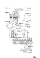
While I Vhave herein shown a preferred embodiment of 'the invention together With ga desirable modiicationthereo-I Wish it to vbe understood that the invention is not confined in its broaderraspects to the specic arrangement vof parts herein` disposed, Abut Y may be embodied in otherarrangements. and by the use of materials and' proportions -Of parts different from those herein vdescribed i Fig. 4 is a fragmentary enlarged section on the line 4 4 of Fig. 3;
Fig. 5 is a plan view of a resilient washer forming a part of the carrier;
Fig. 6 is an enlarged fragmentary section on the line 6-6 of Fig. 5;
Fig. 7 is a developed edge view of the ring shown in Fig. 3;
Fig. 8 is a fragmentary developed view of a portion of one end of the body of the carrier;
Fig. 9 is a fragmentary developed edge view of a second indicator ring;
Fig. 10 is a side elevation of a cash carrier provided with a modified construction of indicator ring;
Fig. 11 is a view similar to Fig. 2 showing a section of such carrier; and
Fig. 12 is a fragmentary elevation of parts shown in Fig. 11. I
The carrier herein illustrated is of that genera-l type more fully described in the patent to `Holdsworth No. 1,585,289, May V18, 1926, although the invention is not necessarily limited to embodiment in this particular form of carrier. The carrier, as herein shown, comprises outer and inner concentric telescoping shells 1 and 2 forming the body of the carrier and the heads 3 and 4 Vsecured to opposite ends of the body. The
one of the heads, for example, the head 3,
and the body of the carrier.
Referring to Fig. 2 for a. more specic description, the numeral 7 designates the closed end of the outer shell 1. The head or bumper 3 is secured to the end member 7 of the shell 1 bymeans of a. pair of rivets or bolts 8. In order. to reinforce the parts, a plate 9 is interposed between the inner ends of the rivets 8 and the inner surface of the end 7 of the shell. At the outer side of the end 7 a spacer plate 10 is arranged, such plate having openings for the rivets 8, and above this spacer plate I provide a resilient or spring metal washer 11 constituting one element of the index retaining means as hereinafter more fully described. Above lthis resilient plate or washer 11 I provide a spacer plate 12 which underlies the driving washer 6, the bumper or head 3 being disposed in engagement with the upper surface of the washer 6. The rivets or bolts 8 hold all of the above parts in rigidly assembled relation.
In accordance with the present invention I provide a rotary index ring having an inwardly directed radial annular flange 13 of substantially the same thickness as the spacer 10, and. Whih. is iat-Grues@ bet-veen outer surface of the end member 7 and the under side of the spring washer 11. This index ring also comprises a cylindrical ange 14 which encircles the shell 1 at a point closely adjacent to the head 3, the overhang of the head providing protection for this ring so that the latter is not readily damaged during the use of the carrier.
The spring plate or washer 11 is preferably provided with one or more, preferably three, ribs, lugs, or bosses 15 conveniently produced by a stamping or punching operation. The radial flange 13 of the index ring is provided with a corresponding series of radial sockets or indentations 16 adapted to receive the ribs 15 of the spring washer. Obviously, the ribs or projections may be on the ring and the sockets or indentations in the washer, if desired.
The outer surface of the cylindrical flange 14 of the index ring is provided with a series of spaced index characteristics, and in Figs. 1 and 7 I have shown such characteristics as consisting of groups of letters of the alphabet. equal distances circumferentially of the flange 14 and are preferably centered on the radial planes of the several sockets 16. Upon the outer surface of the outer shell I provide a designating character or mark such, for example, as the arrow 17 adapted to coopcrate with any -of the index characters on the flange 14 to denote that character or group of characters which has been selected.
Normally the detent ribs 15 are seated in corresponding sockets 16 of the flange 13 and the resiliency of the washer 11 is such as to prevent escape of the detent ribs from the sockets, thus securely holding the index ring in adjusted position. However, as the ribs 15 are preferably rounded and the sockets 16 are likewise rounded, it is possible by application of sufficient force to the flange 14 to turn the index ring so as to bring another character or group of characters opposite to the arrow 17. The user of the carrier may thus vary the designated characteristic with the greatest ease and without employing tools or manipulating special and unusual elements not commonly found in carriers of this type, while at the same time the index ring is securely retained in the proper position. Moreover, the construction thus provided is of very simple character and adds but little to the cost or weight of the carrier, while it is of durable character and not subject to injury nor liable to fail even after long periods of use.
In order to provide a greater range of selection than is furnished by the single ring above described, I provide a second rotary ring.` As here illustrated this ring is at the opposite endof the carrier, such ring being designated by the numeral '19. This ring vis in general of the same construction as These groups are spaced at,-
the index ring previously described, is `retained upon the end of the carrier inthe Vsaine manner, and is provided with the saine .authorizer to note at once whether. the article purchased is to be taken yaway by the purchaser or is to be sent. llfhen the article is to be taken by the purchaser, it is desirable to have the transaction completed more promptly than when the merchandise is to be sent, and thus I have arranged this second ring 19 so that the dispatching clerk can readily indicate to the authorizer whether the article is to be taken or sent. For this purpose I may provide the surface of the outer shell 1 at one or more points with the word Take suitably marked on or impressed in the metal or shell, and I then provide the ring 19 with a window which may be brought into registry with the word Take or which may be turned awa-y from such word so that the lattei' is concealed. It is, of course, to be understood that this particular index characteristic, to wit, the word Take is merely illustrative of any designating characteristic which it kmay be desired to employ and which is -to be rendered visible or alternately to be occulted at the will of the person dispatching the carrier.
In order further to extend the utility of the carrier and the permissive variation in indications which may -be provided, -I may form the ring with a plurality of windows indicated in Fig. 9 at 20, 20a, 20b and 20. I
Vmay also color the exterior surface of this vring designated as 9a so as to form areas of Vdistinctively different appearances, each of tends along the apertured or windowed space. Vith this arrangement it is possible to obtain a wide variation of designations since any one ofthe colors may be combined Vwith the word Take to indicate a certain fact or circumstance or alternately the saine color maybe employed as a blank at the po- -sition of the occulted word Take, thus indicating another fact or circumstance. ,For convenience in indicating the position of the word Take when the latter is occulted by a blank space in the ring, I may provide an -arrow or other mark 21 on the surface of the vcarrier. 'Ihelnuinber of combinationsmay further be increased by .providing the surface of the shell with asrmany of theindex chai'- acteristics (for example, occurrences ofthe word Take) as there are Windowscin the ring, designating each of these several. char- `.acteristicseby a distinctive numeral or letter as, for example, the reina-n numerals I, II,
etc. Y
Other. and further modifications in.4 carryingforward the .underlying principles'herein exposed will doubtless occur to those familiar lwith A the art. Y
Figs. 10,11 and.12 illustrate. a. carrier having ,at the head end, an index ring assembly which embodies the usc of such coloredareas. Since with the arrangement shown in Fig. 9 the colored areas are exposed throughout the entire circumference of the ring, it may not be .19. Preferably the free edge of=.this;flange 14a .isturned outwardly `at 26 .andits outer edge ,is knurled, providing a convenient gripping surface for the fingers of the user.
The outer surface of this flange ,14a may be coloredas previously described, but in .this
.instance such outer surface is protected by means of .a secondary ring, here illustrated .as stationary, comprising a flange 24 overlying the flange 14a', such secondary .ring having, a radial flange .which may if desired be secured in fixed position bymeans of the head ,atta'ching'bolts lor rivets. .Preferably va spacer .25 nia-y be.introducedbetweenrthis .secondary ringandthe Washer 11a. to p-rovide sufficient .space for the movements of the latter. .The protector ring 24: is vfurnished with. a window 27. through whichany one of .the lcolored areas lof the ring laamay be exhibited, .and ifi this4 flange has windows,
.such-.as the .window 200v of Fig. 12, .itispossible to see index characteristics such .as 18a uponthe outersurface of the shellof the carrier. The opposite end of theccarrier may be plainor lia-vea rotary ring and is here shown-providedwith a ring 190 having Windows 191 through which the wordFTake lll() Vor other index characteristic is exposed .sim-
Vilar` to the rin-g 19 on the carrier shown in -Fig.1.
Vteristics can beprovided `upon this lcarrier and that such combinations can befmade up atthearll .0f ..theiiser,Wit-hout @Specialisti fort and with a minimum expenditure of time and without substantially complicating the carrier, adding to its weight, or cutting down the normal area of the access opening.
I claim:
l. A pneumatic dispatch carrier having a cylindrical body portion and an index ring embracing said body portion and turning relatively thereto, said ring having a flange provided with a plurality of circumferentially spaced indentations therein, and detent means including a spring Washer having a boss engageable with the indentations in the ring and exerting force in an axial direction tending to keep the boss engaged with a selected indentation.
2. A pneumatic dispatch carrier having a cylindrical body portion and an index ring embracing said body poition and turning relatively thereto, said ring having a flange, detent element-s on the ring flange, and a spring washer provided with cooperating detent elements, said washer exerting pressure in an axial direction upon the flange thereby normally holding the detent elements thereon in engagement with those on the ring flange.
3. A pneumatic dispatch carrier having a cylindrical body portion and an index ring encircling said body portion and rotatable relatively thereto, said-ring having an annular flange extending radially over one end of the body portion, and resilient detent means movable in an axial direction and noi'- mally engaging the flange to retain the ring in selected position said flange having elements thereon with which the detent means engage. i
4. A carrier for pneumatic dispatch systems comprising a cylindrical body portion and a rotatable ring encircling said body portion, said ring comprising a radially extending annular flange and arcylindrical flange, and a resilient plate engaging the radial flange, said plate and flange having cooperating detent elements normally operative to retain the ring in selected position, said detent elements slipping to permit rotation of the ring when sufficient rotative force is applied to the latter.
5. A carrier for pneumatic dispatch systems comprising a cylindrical body portion and a rotatable ring encircling said body portion adjacent one end thereof, said ring comprising an annular flange extending radially over that end of the body portion and a cylindrical flange, a resilient plate engaging the radial flange, the plate having a detent tooth and the radial flange having a socket engageable by the tooth for retaining the ring in selected position.
6. A carrier ofthe class described comprising a cylindrical body and a bumper or r head at the end of the body, a rotatable ring encircling the body at a point adjacent to the head, said iing comprising a cylindrical flange having a series of distinctive index characteristics upon its outer surface and av radial annular flange having a series of sockets therein and interposed between the end of the body and the bumper or head, and a resilient washer interposed between the bumper and said radial flange, the washer having a detent tooth engageable with any of a series of sockets in said radial flange, the sockets corresponding in number and spacing with the series of index character'- istics on the cylindrical flange.
7. A carrier of the class described comprising a cylindrical body and a head secured to the end of the body, a rotatable ring encircling the body at a point adjacent to the head, said ring having a cylindrical flange provided with a window opening and a radial annular flange interposed between the body and head, a resilient Washer between the head and said radial flange, the flange and washer having cooperating detent elements axially movable and 'normally operative to hold the ring in selected position, but permitting it to rotate when subjected to suliicient rotative force, and designating characteristics upon the outer surface of the body beneath the cylindrical flange of the rotary ring.
8. A carrier of the class described coin- Vprising a body provided with ai head at each end and an access opening in its side wall intermediate the heads, a movable indicator mounted between said heads, said indicator having a plurality of differently colored areas, and a relatively fixed shield, said shield having a window, the shield concealing all of the colored portionof said indicator except such as is exhibited through the window.
9. A carrier of the class described comprising a body provided with a head at each end and an access opening in its side wall intermediate tlie heads, a rotary ring encircling said body, saidV ring having a series of windows therein separated by'blank spaces, the body having a distinguishing index characteristic visible through any selected one of said windows when the ring is properly positioned, but invisible when the ring is turned to an intermediate position, and series of differently colored areas upon the i'ing, there being one area of each color corresponding to each window whereby the color of the area through which the characteristic is visible may be determined bythe window selected to register therewith.
l0. A pneumatic dispatch carrier comprising a cylindrical body portion having thereon an index characteristic, a relatively inevable ring surrounding the body portion over said characteristic. and having a window therein through which such characteristic may be exposed and a stationary Ting SUF- rounding said movable ring and having a window therein registering with said characteristic, whereby the characteristic will be visible when the window in the stationary ring coincides with the window in the movable ring.
11. A pneumatic dispatch carrier comprising a cylindrical body portion having thereon an index characteristic, a relatively movable ring surrounding the body portion over said characteristic, and having a seri-es of windows therein through any of which the characteristic on the body portion may be exposed, the surface of the ring at each window being treated, and a second ring surrounding said first ring and having a window therein larger than the windows of the first ring and adapted to register with said characteristic wherebywhen the windows in the two rings register th-e characteristicv on the body portion and the treated surface at the window of the first ring may be visible.
12. A pneumatic dispatch carrier comprising a cylindrical body portion having thereon an index characteristic, a relatively movable ring surrounding the body portion over said characteristic, and having a series of windows therein through any of which the characteristic on the body portion may be exposed, the surface of the ring at each window being provided with color which contrasts with the color at the other windows, and a second ring surrounding said first ring and having a window therein larger than the windows of the first ring and adapted to register with said characteristic whereby when windows in the two rings register, the characteristic on the body portion and the color at the selected window of the first ring may be visible.
13. A pneumatic dispatch carrier comprising a cylindrical body portion having thereon an index characteristic, a relatively movable ring surrounding the body portion over said characteristic, and having a series of windows therein through any of' which the characteristic on the body portion may be exposed, the surfaces of said ring between the windows being treated, and a stationary ring surrounding said first ring and having a window therein which registers with the characteristic whereby when windows in the two rings coincide, the characteristic on the body portion will be visible and when the windows do not coincide one of the treated surfaces of the first ring will be visible.
14. A pneumatic dispatch carrier comprising a cylindrical body portion having thereon an index characteristic, a relatively movable ring surrounding the body portion over said characteristic, and having a series of windows therein through any of which the characteristic on the body portion may be exposed, the surfaces of the ring at each window being provided with color which contrasts with the color at the other windows, and the surfaces of the ring between the windows being similarly provided with contrasting colors, and a stationary ring surrounding said irst ring and having a window therein larger than the windows of the first ring and which registers with the characteristic whereby when windows in the two rings register the characteristic on the body portion and the color at the selected window of the first ring will be visible and When the windows in the two rings do not register the color of a selected surface of the first ring will be visible.
Signed by me at Syracuse, New York, this 15th day of March, 1928.
HAROLD F. rVIEAU.
Priority Applications (1)
| Application Number | Priority Date | Filing Date | Title |
|---|---|---|---|
| US262557A US1908492A (en) | 1928-03-17 | 1928-03-17 | Pneumatic dispatch carrier |
Applications Claiming Priority (1)
| Application Number | Priority Date | Filing Date | Title |
|---|---|---|---|
| US262557A US1908492A (en) | 1928-03-17 | 1928-03-17 | Pneumatic dispatch carrier |
Publications (1)
| Publication Number | Publication Date |
|---|---|
| US1908492A true US1908492A (en) | 1933-05-09 |
Family
ID=22998008
Family Applications (1)
| Application Number | Title | Priority Date | Filing Date |
|---|---|---|---|
| US262557A Expired - Lifetime US1908492A (en) | 1928-03-17 | 1928-03-17 | Pneumatic dispatch carrier |
Country Status (1)
| Country | Link |
|---|---|
| US (1) | US1908492A (en) |
-
1928
- 1928-03-17 US US262557A patent/US1908492A/en not_active Expired - Lifetime
Similar Documents
| Publication | Publication Date | Title |
|---|---|---|
| US3755908A (en) | Pipeline pig | |
| US1823130A (en) | Typewriting machine | |
| CA1062639A (en) | Overrunning clutch and retainer and roller assembly therefor | |
| DE69303227D1 (en) | Childproof closure with display device | |
| US1908492A (en) | Pneumatic dispatch carrier | |
| GB1344425A (en) | Ear protectors | |
| US1353531A (en) | Marking-card for milk-bottles | |
| US3177724A (en) | Tire gauge housing | |
| US4219943A (en) | Time teaching clock | |
| GB937479A (en) | Improvements in or relating to retaining rings | |
| GB2049862A (en) | Retaining ring and a clutch release assembly including the retaining ring | |
| US1592568A (en) | Figure wheel | |
| US2754370A (en) | Telephone attachment | |
| US1585289A (en) | Frank holdswobth | |
| US2668369A (en) | Cipher device | |
| US3030016A (en) | Golf score register | |
| US2026932A (en) | Combination lock | |
| US2997150A (en) | Grain spout | |
| US2777228A (en) | Finger dial for dial telephones | |
| GB1026714A (en) | Improvements relating to a gasket and locating ring assembly | |
| US3032003A (en) | Portable dairyman's indicator | |
| US3146868A (en) | Rotary card index with brake | |
| US1343112A (en) | Tbawslatiitg-chabt | |
| US1868903A (en) | Carrier for dispatch systems | |
| US2509833A (en) | Magnifying and light concentrating device for telephone dials |