US1908402A - Method and apparatus for joining woven wire fabric - Google Patents
Method and apparatus for joining woven wire fabric Download PDFInfo
- Publication number
- US1908402A US1908402A US532803A US53280331A US1908402A US 1908402 A US1908402 A US 1908402A US 532803 A US532803 A US 532803A US 53280331 A US53280331 A US 53280331A US 1908402 A US1908402 A US 1908402A
- Authority
- US
- United States
- Prior art keywords
- base
- fabric
- edges
- arms
- clamping
- Prior art date
- Legal status (The legal status is an assumption and is not a legal conclusion. Google has not performed a legal analysis and makes no representation as to the accuracy of the status listed.)
- Expired - Lifetime
Links
- 239000004744 fabric Substances 0.000 title description 94
- 238000000034 method Methods 0.000 title description 23
- 239000000463 material Substances 0.000 description 5
- 238000005219 brazing Methods 0.000 description 4
- 238000005476 soldering Methods 0.000 description 4
- 230000000717 retained effect Effects 0.000 description 3
- 238000003466 welding Methods 0.000 description 3
- 238000010276 construction Methods 0.000 description 2
- 238000007429 general method Methods 0.000 description 2
- MYLBTCQBKAKUTJ-UHFFFAOYSA-N 7-methyl-6,8-bis(methylsulfanyl)pyrrolo[1,2-a]pyrazine Chemical compound C1=CN=CC2=C(SC)C(C)=C(SC)N21 MYLBTCQBKAKUTJ-UHFFFAOYSA-N 0.000 description 1
- 238000009825 accumulation Methods 0.000 description 1
- 238000007599 discharging Methods 0.000 description 1
- 238000003780 insertion Methods 0.000 description 1
- 230000037431 insertion Effects 0.000 description 1
- 238000012986 modification Methods 0.000 description 1
- 230000004048 modification Effects 0.000 description 1
Images


Classifications
-
- B—PERFORMING OPERATIONS; TRANSPORTING
- B21—MECHANICAL METAL-WORKING WITHOUT ESSENTIALLY REMOVING MATERIAL; PUNCHING METAL
- B21F—WORKING OR PROCESSING OF METAL WIRE
- B21F33/00—Tools or devices specially designed for handling or processing wire fabrics or the like
- B21F33/007—Connecting wire network
Definitions
- This invention relates to a new and useful method and apparatus for joining woven wire fabric, known as paper machine wire or any other wire fabric of a light nature.
- a further object of the invention is to provide a simplified method of joining the fabric which may be readily followed to produce a' durable and unstitched joint in a minimum of time.
- a further object of the invention is to provide a method for forming a durable, butted and welded joint.
- a further object is to provide an improved method and apparatus for bringing the opposed edges of woven wire fabric into accurate abutment and maintaining such accurate abutment while the joint therebetween is actually formed whereby, not only is the operation of forming. the joint greatly facilitated and expedited, but a much more perfect joint is obtainable than hitherto and one which is substantially flush with the faces of the fabric and in which the mesh format on JOINING WOVEN "WIRE FABRIC 1931. Serial No. 532,803.
- a further object of the invention is to provide an improved apparatus suitable for use in the improved method which is of simple character, the parts of which will readily cooperate to accurately hold and move the free edges of the fabric in position to facilitate the oining thereof.
- the free edges of the wire fabric are positioned adjacent each other and firmly retained in such position.
- the joining of the edges of the wire fabric is necessarily effected progressively across the width of the fabric and in carrying out the method the free edges of the fabric not 'immedia-tely to be subjected to the joining operation are spaced apart.
- the free edges of the fabric not 'immedia-tely to be subjected to the joining operation are spaced apart.
- the fabric to be immediately joined the fabric is firmly gripped and the adjacent edges of this section brought into abutment andunited by Welding, brazing or soldering upon application of. heat to the butted oint. This operation is repeated progressivelyacross the entire width of the fabric until the free edges thereof have been completely united.
- Figure 1 is a perspective View of one form .of apparatus which may be employed in the joining of the fabric.
- Figure 2 is a side elevation of the apparatus.
- A indicates the apparatus as a whole, including the base 10 of any suitable form provided with an upper plane surface 11.
- the base is preferably slotted in the middle as at 12 to communicate with a central longitudinal extending chamber 13 formed in the base, which will be more fully referred i
- On one end of the base is" rigldly mounted a supporting structure B to hereinafter.
- the base plate 14 which may be cast or machined inone piece and is formed with the base plate 14 which is adapted to connect with the base 10.
- the base plate 14 is preferably counter-sunk in the base 10, as clearly indicatedin Figure 5.
- the supporting structure B includes a Web or rib 15, more fully referred to hereinafter, which connects the base plate 14 with the upper portion of the supporting structure B, which includes the web 16 spacing apart the upper and lower plates 17 and 18 which form therebetween the channels 19 and 20.
- Slidably mounted within the channels 19 and 20 and therefore between the plates 17 and 18 are laterally movable arms 21 and 22 which are adapted to extend longitudinally substantially the length of the base 11 and are movable laterally in the channels 19 and 20 by means of any suitable mechanism.
- Figure 1 One form of this mechanism is illustrated in Figure 1, which consists in the bifurcated lugs 23 and 24 rigidly connected to each of the arms 21 and 22, to which are pivotally connected the toggle links 25 in turn pivotally connected at their opposite ends to a cross-yoke .26 which is carried by the movable screw-threaded shaft 27 adapted to extend into the top plate 17 of the supporting structure B, the screw-threaded shaft being controlled by the knurled operating member 28.
- rigidly secured guide members 30 are mounted preferably by means of channels cut in the plate 17 and these guiding members are formed with extensions on each side 31 designed to enter into grooves 32 in the arms 21 and 22 which are cut at right angles to their longitudinal axis so that, when these arms move inwardly or outwardly, by reason of the guides described, they must necessarily move in parallel relation.
- movable clamping members 33 and 34 On the forward ends of the arms 21 and 22 are secured movable clamping members 33 and 34:, these clamping members being preferably machined as at 35 so as to provide an edge 36 approximating a knife edge adjacent the plane surface 11 of the base 10. These clamping members are designed to move vertically with respect to the arms 21 and 22 and also with respect to the base 10. To accomplish this, screw-threaded shafts 37 and 38 extend through the arms 21 and 22 respectively to enter into the clamping members 33 and 34, these screw-threaded shafts being mounted in the arms 21 and 22, as clearly indicated in Figure 3, to readily turn in the arms, the screw threading on the shafts being designed to-engage with'corresponding screw-threading in the clamping members 33 and 34.
- the clamping members 33 and 34 will either move upwardly or downwardly, according to the direction of movement of said operating members so that these clamping members may be made to firmly engage with the base or to grip material inserted between the clamping members and the base, or the clamping members may be moved upwardly from the base to release material gripped between these members and the base.
- suitable guide members 42 are rigidly carried on the arms 21.
- the arms 21 and 22 may be urged towards each other and, consequently, the fabric gripped by the clamping members 33 and 34 will be thereby urged towards each other so that they will abut over the slot 12.
- the arms 21 and 22 are recessed or cut away at 44 so that the major longitudinally extending area thereof is of reduced width in comparison with the inner ends of these members which are adapted to slide within the slots 19 and 20 in a supporting structure B.
- the chamber 13 formed in the middle of the base below the slot 12 is designed to permit the heat to penetrate the butted joint effected between the free edges of the wire, and the heat will escape by travelling along the chamber and discharging through any of the openings available.
- the clamping members through the medium of the arms 21 and 22 may be moved simultaneously towards one another or, if desired, one arm and, consequently, one clamping member may be held stationary and the other arm and clamping member caused to be movable transversely of the block, as above referred to, so that in this case the arms will move relatively to one another and the edges of the wire fabric gripped by the clamping members will be caused to move relatively to one another.
- one edge of the gripped wire fabric may be moved to abut the other edge to which it is to be joined, While said other edge is held stationary.
- a structure of the character illustrated in Figures 8 and 9 may be employed, which includes the arms 21 and 22, as above described, but the arm 22 is held rigidly in the supporting structure B in any suitable Way, as for instance by pins 22a, while the arm 21 is capable of transverse movement.
- guides 49 are rigidly secured to the arm 21 and adapted to move in the guideways 50 in the web 16.
- This structure may be of any desirable nature and is shown in the form of dowel pins and corresponding holes within which the pins are designed to slide.
- the one arm 21 may be caused to move transversely of the base towards and away from the opposite arm 22 which is held stationary.
- This mode of operation can also be followed in the structure illustrated in Figure 1 if desired and, to this end, it is only necessary to hold one of the arms stationary by inserting pins or retaining members through the supporting structure, such as at 51, thus securely holding one arm against movement and, upon disconnecting the corresponding toggle link 25 which was designed to operate the arm, the action just described will take place, viz. the arms will move relatively to one another.
- the free ends of the wire fabric are inserted through the space 39 between the upper surface 11 of the base and the bottom of the clamping members 33 and 3t and are moved to a position adjacent the slot 12.
- the arms 21 and 22 Upon turning the operating member 28 of shaft 27 in one direction the arms 21 and 22 will be caused to move towards each other or one arm may becaused to move towards the other which is held stationary and the free edges of the fabric in the area of the clamping members which firmly grip the fabric will be brought together over the slot 12 to directly abut along the length of the clamping members, the web 15, as previously referred to, spacing the major length of the remaining portion of the fabric, as indicated in Figure 7, so that this web will prevent overlapping and buckling of the free edges of the fabric not retained by the clamps and thus will provide for an accurate and eflicient abutment of the free edges.
- the supporting structure and, consequently, the web 15 is spaced longitudinally from the clamping members a substantial distance so that, when the free edges of the fabric are spaced apart by the web, the spacing after the free edges have been brought into abutment is of very gradually increasing width which will permit abutment of the free edges in an accurate manner with very slight distortion of the fabric.
- the general method as followed according to the present invention consists in directly positioning the free edges of the fabric in substantially parallel spaced apart relation adjacent one another, firmly gripping said fabricto retain it in said position, drawing the opposed edges into abutment and uniting the said abutting edges to form a joint therealong.
- lhe method also includes the spacing of ungripped portions of the fabric, as previously referred to, obviatin any buckling or overlapping of the free e ges and eliminating inaccuracy in the joining operation, and repeating the general method progressively throughout the length of the ed es to be joined until they are united throug out their complete length in a fine, durable seam.
- the 'oinin of the edges after'they have been roug t into abutment is effected bywelding, brazing or soldering through the application of heat.
- What we claim as our invention is l.
- A. method of joining woven wire fabric which consists in placing the free edges of said fabric to be-joined adj acent one another in spaced apart relation, retaining the fabric in said position and progressively bringing sections of said edges of said fabric into abutment, and joining said abutted edges by the application of heat.
- a method of joining the edges of woven wire fabric which consists in securely clamping sections of said edges in abutment While positively retaining the remaining portions of said edges in spaced-apart relation, uniting the abutting sections to form a joint therealong, and repeating the said operation progressively across the entire width of the edges to be joined.
- a method of joining woven wire fabric which consists in placing the edges to be joined in spaced-apart relation, gripping opposing portions of said fabric, drawing the edges of said gripped portions into abutment, while retaining the remainder of the opposed edges spaced apart, uniting the abutting edges to form a joint therealong, and repeating said operations progressively across the entire width to be joined.
- Apparatus for use in joining the edges of wire fabric comprising a base formed with a longitudinal slot therein, opposed spacedapart fabric clamping elements co-active with and overlying the base at either side of the slot, and a spacing element overlying the slot in the base and spaced longitudinally from the clamping elements.
- Apparatus for use in joining the edges of wire fabric comprising a base formed with a longitudinal slot therein, opposed spaced-apart fabric clamping elements coactive with and overlying the base at eit side of the slot, means for moving said clamping elements towards and away from the base, means for moving at least one of said clamping members transversely of the base towards and away from the other, and a fabric spacing element carried on the base and spaced longitudinally from the clamping elements.
- Apparatus for use in joining the edges of wire fabric comprising a base formed with a longitudinal slot therein, opposed spaced-apart fabric clamping elements coactive with and overlying the base at either side of the slot, means for moving said clamping elements towards and away from the base, means for moving at least one of said clamping members transversely of the base towards and away from the other, and a spacing element carried on the base overineaaoa lying the slot and spaced therein longitudinally from the clamping elements.
- Apparatus for use in joining the edges of Wire fabric comprising a base formed with a longitudinal slot therein, opposed spacedapart fabric clamping elements co-active with and overlying the base at either side of said slot, said clamping elements being shorter than the base, means for moving said clamping elements towards and away from the base, means for moving at least one of said clamping elements transversely of the base towards and away from the other, and a spacing element overlying the slot in the base and spaced longitudinally from the clamping elements.
- Apparatus for use in joining the edges of wire fabric comprising a base, opposed parallel spaced-apart fabric-clamping elements co-acting with and overlying the base, and a spacing element carried by the base and spaced longitudinally from the clamping elements.
- Apparatus for use in joining woven wire fabric comprising a base, a pair of rigidly held movable arms carried by the base in spaced apart relation, clamping members carried by said arms and coactive with said base, means for vertically adjusting said clamping members with respect to the base, and means for moving at least one of said arms transversely of the base.
- Apparatus for use in joining woven wire fabric comprising a base formed with a longitudinal slot therein, a supporting structure mounted on said base, a pair of longitudinally extending arms carried by said supporting structure and adapted to overlie the base on each side of said slot in parallel relation, clamping members carried by said arms and coactive with said-base, means for vertically adjusting said clamping members towards and away from said base to engage or disengage with material placed upon the base, and means for transversely moving at least one of said arms towards and away from the other.
- a method of joining the opposed edges of woven wire fabric to form a flush joint therebetween which consists in placing said opposed edges adjacent one another in spaced apart relation, progressively bringing limited sections of said opposed edges into accurate abutment and uniting the thus abutted edges by the application of heat.
- a method or" joining the opposed edges of woven wire fabric to form a flush joint therebetween which consists in' securely clamping opposed limited sections of said edges in abutment while positively retaining the remaining opposed portions of said edges in spaced apart relation, uniting the abutted sections by the application of heat, and repeating said operations progressively progressively across the entire width of the edges to be joined.
- Apparatus for use in joining the edges of woven wire fabric comprising, a base formed with a lingitudinal slot therein, opposed spaced apart fabric clamping elements co-active with and overlying the base at either side of said slot and disposed parallel thereto, said clamping elements being shorter than the base, means for moving said clamping elements into and out of clamping engagement with the base, means for moving at least one of said clamping elements transversely of the base towards and away from the other clamping element while in gripping engagement with the base, and a fabric spacing element overlying the slot in the base and spaced longitudinally from the clamping elements.
- Apparatus for use in joining the edges of woven wire fabric comprising means for positioning said edges in opposed substantially parallel spaced apart relation, means for gripping said fabric adjacent to and along opposed limited sections of said edges, means for moving the edges of said gripped limited sections into abutment, and means for positively maintaining the edges of the remaining ungripped portions of the opposed edges in spaced apart relation.
- Apparatus for use in joining the edges of woven wire fabric comprising means for positioning said edges in opposed substantially parallel spaced apart relation, means for gripping said fabric adjacent to and along opposed limited sections of said edges,
- Apparatus for use in oining the edges of woven wire fabric comprising, a base, a pair of spaced apart parallel arms supported in spaced relation above and overlying the base, a clamping member carried by each of said arms and positioned between its arm and the base, means for moving said clamping members perpendicularly to the base into and out of clamping engagement therewith, and means for moving at least one of said arms in parallelism with and towards and away from the other arm while in clamping engagement with the base.
- Apparatus for use in joining the edges of woven wire fabric comprising, a base formed with a longitudinal slot therein, a pair of spaced apart longitudinally extending parallel arms supported in spaced relation above and overlying the base, a clamping member carried by each of said arms and positioned between its arm and the base, said clamping members disposed opposite to each other at either side of said slot and parallel therewith, said clamping members being shorter than the base, means for moving said clamping members perpendicularly to the base into and out of clamping engagement therewith, means for moving at least one of said arms transversely of the base in parallelism with and towards and away from the other arm while in clamping engagement with the base, and a spacing element in registration with the slot in the base and spaced longitudinally from the clamping members.
- Apparatus for use in joining the edges of woven wire fabric comprising, a base formed with a longitudinal slot therein, a pair of spaced apart longitudinally extending parallel arms supported in spaced relation above and overlying the base, a clamping member carried by each of said arms and positioned between its arm and the base, said clamping members disposed opposite to each other at either side of said slot and parallel therewith, said clamping members being shorter.
- Apparatus for use in joining woven wire fabric comprising a base formed with reoaeoe a longitudinal slot therein, a supporting structure mounted on said base, a pair of longitudinally extending arms carried by said supporting structure and adapted to overlie the base on each side of said slot in parallel relation, clamping members carried by said arms and co-active with said base, means for vertically adjusting said clamping members towards and away from said base to engage or disengage with material placed upon the base, and means for transversely movingat least one of said arms towards and away fromthe other while in clamping engagement with the base, and a spacing element carried by the supporting structure and in registration with the slot in the base, said spacing element spaced longitudinally from the clamping members.
- Apparatus for use in joining the edges of woven wire fabric comprising, a base formed with a longitudinal slot therein, a supporting structure mounted upon the base adjacent to one end thereof, a pair of spaced apart parallel arms carried by said suppofiing structure, said arms longitudinally over-' lying the base, in spaced parallel relation thereabove and disposed on either side of and parallel to said slot, said arms extending substantially to the end of the base remote from the supporting structure, a clamping member carried by each of said arms at the end thereof remote from the supporting structure and positioned between its arm and the upper face of the base, said clamping members disposed opposite to each other at either side of said slot, said clamping members being spaced longitudinally from the supporting structure, means for moving said clamping members perpendicularly to the base into and out of clamping engagement therewith, means for moving at least one of said arms transversely of the base inparallelism with and towards and away from the other arm while in clamping engagement with the base, and a spacing element carried by the supporting structure and in registration with
- Apparatus for use in joining the edges of woven wire fabric comprising a base and movable fabric clamping members connected to said base solely through a member extending between the edges of the fabric to be joined.
- Apparatus for use in joining the edges of woven wire fabric comprising a base and movable fabric clamping members connected to said base solely through a member situated substantially centrally of the width of said base.
- Apparatus for use in joining the edges of woven wire fabric comprising a base and movable fabric clamping members connected to said base solely through a web extending longitudinally of the base and situated substantially centrally of the width thereof.
- Apparatus for use in joining the edges of Woven wire fabric comprising a base and a support for movable fabric clamping members, said support being connected to said base solely through a member extending between the edges of the fabric to be joined.
- Apparatus for use in joining the edges of woven wire fabric comprising a base and a support for movable fabric clamping members, said support being connected to said I base solely through a narrow web extending longitudinally of the base and between the edges of the fabric to be joined.
Landscapes
- Engineering & Computer Science (AREA)
- Mechanical Engineering (AREA)
- Treatment Of Fiber Materials (AREA)
Description
y 1933- J. R. BUCHANAN ET AL 1 ,908,402 METHOD AND APPARATUS FOR JOINING WOVEN WIRE FABRIC Filed April 25, 1951 3 Sheets-Sheet 1 MIII May 9, 1933.
METHOD J. R. BUCHANAN ET AL 1,908,402 AND APPARATUS FOR JOINING WOVEN WIRE FABRIC Filed April 25, 1951 3 Sheets-Sheet 2 Bushman 77701175 M y 1933- J. R. BUCHANAN ET AL 1,908,402
METHOD AND APPARATUS FOR JOINING WOVEN WIRE FABRIC Filed April 25, 1931 3 Sheets-Sheet 3 Patented May Q, 133
UNHTE stars PEN? @FEQGE JOHN R. BUCHANAN AND THOMAS M. CRAY, OF OTTAWA, ONTARIO, CANADA METHOD AND APPARATUS FOR Application filed April 25,
This invention relates to a new and useful method and apparatus for joining woven wire fabric, known as paper machine wire or any other wire fabric of a light nature.
} It has been customary to join woven wire fabric by stitching the free ends of the fabric together throughout their width, which practice has many disadvantages, Foremost among these disadvantages are the length of time required to join the edges of the fabric and the cost of the upkeep of the fabric when used on paper machines and the like due to the fact that a stitched oint causes the accumulation of foreign material therein which necessitates that the machines be stopped to clean the joint thoroughly. Furthermore, seams oined with wire being of a necessarily different construction from the fabric so joined, are apt to wear out sooner than the body of the fabric, making the entire belt of fabric useless for further service. It is, therefore, an object of the present invention to avoid such disadvantages by forming according to an improved method a joint which obviates stitching or, in other words, is an unstitched joint of durable construction.
A further object of the invention is to provide a simplified method of joining the fabric which may be readily followed to produce a' durable and unstitched joint in a minimum of time.
A further object of the invention is to provide a method for forming a durable, butted and welded joint.
A further object is to provide an improved method and apparatus for bringing the opposed edges of woven wire fabric into accurate abutment and maintaining such accurate abutment while the joint therebetween is actually formed whereby, not only is the operation of forming. the joint greatly facilitated and expedited, but a much more perfect joint is obtainable than hitherto and one which is substantially flush with the faces of the fabric and in which the mesh format on JOINING WOVEN "WIRE FABRIC 1931. Serial No. 532,803.
is not interrupted or interfered with at the joint but is substantially regular, uniform and continuous across the joint.
A further object of the invention is to provide an improved apparatus suitable for use in the improved method which is of simple character, the parts of which will readily cooperate to accurately hold and move the free edges of the fabric in position to facilitate the oining thereof.
lVith these and other objects in view, the invention consists in the novel method and apparatus hereinafter described in detail.
According to the method, the free edges of the wire fabric are positioned adjacent each other and firmly retained in such position. The joining of the edges of the wire fabric is necessarily effected progressively across the width of the fabric and in carrying out the method the free edges of the fabric not 'immedia-tely to be subjected to the joining operation are spaced apart. Along a section of the free edges of the fabric to be, immediately joined the fabric is firmly gripped and the adjacent edges of this section brought into abutment andunited by Welding, brazing or soldering upon application of. heat to the butted oint. This operation is repeated progressivelyacross the entire width of the fabric until the free edges thereof have been completely united.
In order to more fully illustrate the method and explain the apparatus which may be used in conjunction therewith, reference is made to the accompanying drawings, in which:
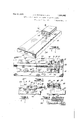
Figure 1 is a perspective View of one form .of apparatus which may be employed in the joining of the fabric.
Figure 2 is a side elevation of the apparatus.
ratus illustrating the relative positions of I Figure 9 is a fragmentary detailpartly in section of the operating mechanism illustrated in Figure 8.
Referring more particularly to the drawings, A indicates the apparatus as a whole, including the base 10 of any suitable form provided with an upper plane surface 11. The base is preferably slotted in the middle as at 12 to communicate with a central longitudinal extending chamber 13 formed in the base, which will be more fully referred i On one end of the base is" rigldly mounted a supporting structure B to hereinafter.
which may be cast or machined inone piece and is formed with the base plate 14 which is adapted to connect with the base 10. The base plate 14 is preferably counter-sunk in the base 10, as clearly indicatedin Figure 5.
The supporting structure B includes a Web or rib 15, more fully referred to hereinafter, which connects the base plate 14 with the upper portion of the supporting structure B, which includes the web 16 spacing apart the upper and lower plates 17 and 18 which form therebetween the channels 19 and 20. Slidably mounted within the channels 19 and 20 and therefore between the plates 17 and 18 are laterally movable arms 21 and 22 which are adapted to extend longitudinally substantially the length of the base 11 and are movable laterally in the channels 19 and 20 by means of any suitable mechanism.
One form of this mechanism is illustrated in Figure 1, which consists in the bifurcated lugs 23 and 24 rigidly connected to each of the arms 21 and 22, to which are pivotally connected the toggle links 25 in turn pivotally connected at their opposite ends to a cross-yoke .26 which is carried by the movable screw-threaded shaft 27 adapted to extend into the top plate 17 of the supporting structure B, the screw-threaded shaft being controlled by the knurled operating member 28. Thus, when the knurled operating member 28 is rotated in one direction, the screw-threaded shaft will move upwardly in the plate 17 and consequently draw inwardly upon the bifurcated lugs 23, necessaril drawing the arms 21 and 22 inwardly, the mward movement being permitted by reason of the spaces 29 which exist between the web 16 and the inner side of the arms 21 and 22 when the arms are in their normal position. In order to provide for parallel movement of these arms in the top of the plate 17, rigidly secured guide members 30 are mounted preferably by means of channels cut in the plate 17 and these guiding members are formed with extensions on each side 31 designed to enter into grooves 32 in the arms 21 and 22 which are cut at right angles to their longitudinal axis so that, when these arms move inwardly or outwardly, by reason of the guides described, they must necessarily move in parallel relation.
On the forward ends of the arms 21 and 22 are secured movable clamping members 33 and 34:, these clamping members being preferably machined as at 35 so as to provide an edge 36 approximating a knife edge adjacent the plane surface 11 of the base 10. These clamping members are designed to move vertically with respect to the arms 21 and 22 and also with respect to the base 10. To accomplish this, screw-threaded shafts 37 and 38 extend through the arms 21 and 22 respectively to enter into the clamping members 33 and 34, these screw-threaded shafts being mounted in the arms 21 and 22, as clearly indicated in Figure 3, to readily turn in the arms, the screw threading on the shafts being designed to-engage with'corresponding screw-threading in the clamping members 33 and 34. In normal position they are held tightly against the arms 21 and 22 so that a space 39 exists between the plane surface 11 of the base 10 and the bottom of the clamping members 33 and 34, see Figures 3 and 5. This space is sufiicient to permit of the insertion of wire fabric or the like between the base 10 and the clamping members .33 and 34 and allows of relative movement of the clamping members between the arms 21 and 22 and the base 10. Thus, when the operating members 40 and 41 of the shafts 37 and 38 are turned in one direction or the other, the clamping members 33 and 34will either move upwardly or downwardly, according to the direction of movement of said operating members so that these clamping members may be made to firmly engage with the base or to grip material inserted between the clamping members and the base, or the clamping members may be moved upwardly from the base to release material gripped between these members and the base. In order to maintain in all positions a proper alignment between these clamping members and the arms'2l and 22, suitable guide members 42 are rigidly carried on the arms 21.
and 22 and adapted to extend into guideways 43 in the clamping members. "These guide members 42 in the form shown are substanthe inner edges 36 of the clamping members 33 and 34 are adapted to lie normally adjacent the slot 12 in the base 10, the clamping members being in parallel relation therewith. The clamping members are, of course, designed to grip the wire fabric adjacent the free edges thereof between the surface 11 of the base 10 and said members and, consequently, when the fabric is properly inserted between these clamping members and the base and gripped in that position, the edges of this fabric will lie substantially parallel with the slot 12 in the base, the edges being, of course, separated towards one end of the base 10 by means of the web 15.
On actuation of the operating member 28 of threaded shaft 27 in one direction, as previously explained, the arms 21 and 22 may be urged towards each other and, consequently, the fabric gripped by the clamping members 33 and 34 will be thereby urged towards each other so that they will abut over the slot 12. When they are brought into this abutting relation they are firmly joined by welding, brazing or soldering through the application of heat thereto and, in order to permit of a clear working space for this step, the arms 21 and 22 are recessed or cut away at 44 so that the major longitudinally extending area thereof is of reduced width in comparison with the inner ends of these members which are adapted to slide within the slots 19 and 20 in a supporting structure B.
The chamber 13 formed in the middle of the base below the slot 12 is designed to permit the heat to penetrate the butted joint effected between the free edges of the wire, and the heat will escape by travelling along the chamber and discharging through any of the openings available.
According to one form of the apparatus, the clamping members through the medium of the arms 21 and 22 may be moved simultaneously towards one another or, if desired, one arm and, consequently, one clamping member may be held stationary and the other arm and clamping member caused to be movable transversely of the block, as above referred to, so that in this case the arms will move relatively to one another and the edges of the wire fabric gripped by the clamping members will be caused to move relatively to one another. In other words, through the movable arm and its attached clamping member, one edge of the gripped wire fabric may be moved to abut the other edge to which it is to be joined, While said other edge is held stationary. In effecting this step a structure of the character illustrated in Figures 8 and 9 may be employed, which includes the arms 21 and 22, as above described, but the arm 22 is held rigidly in the supporting structure B in any suitable Way, as for instance by pins 22a, while the arm 21 is capable of transverse movement. In effecting this movement that this. arm move in parallel relation with" respect to slot 12 in the base and, to provide for this type of movement, guides 49 are rigidly secured to the arm 21 and adapted to move in the guideways 50 in the web 16. This structure may be of any desirable nature and is shown in the form of dowel pins and corresponding holes within which the pins are designed to slide. It is readily apparent, therefore, that the one arm 21 may be caused to move transversely of the base towards and away from the opposite arm 22 which is held stationary. This mode of operation can also be followed in the structure illustrated in Figure 1 if desired and, to this end, it is only necessary to hold one of the arms stationary by inserting pins or retaining members through the supporting structure, such as at 51, thus securely holding one arm against movement and, upon disconnecting the corresponding toggle link 25 which was designed to operate the arm, the action just described will take place, viz. the arms will move relatively to one another.
In following out the method with the apparatus described, the free ends of the wire fabric, as indicated in Figure 3, are inserted through the space 39 between the upper surface 11 of the base and the bottom of the clamping members 33 and 3t and are moved to a position adjacent the slot 12. Through the actuation of the operating members 40 and 41 of the shafts 37 and 38, the clamping members 33 and 34 are caused to grip the fabric firmly in that position so that that section of the fabric underlying the clamping members is firmly held whereas the re-= maining portion of the fabric is loosely held, the web 15 which overlies or is in registration with the slot 12 serving as a spacing element to maintain the edges of this loosely held portion spaced apart, as clearly indicated in Figure 7. Upon turning the operating member 28 of shaft 27 in one direction the arms 21 and 22 will be caused to move towards each other or one arm may becaused to move towards the other which is held stationary and the free edges of the fabric in the area of the clamping members which firmly grip the fabric will be brought together over the slot 12 to directly abut along the length of the clamping members, the web 15, as previously referred to, spacing the major length of the remaining portion of the fabric, as indicated in Figure 7, so that this web will prevent overlapping and buckling of the free edges of the fabric not retained by the clamps and thus will provide for an accurate and eflicient abutment of the free edges. The free edges which have been brought into abutment over the slot 12 are then united by welding, brazing or soldering upon the application of heat, and a very firm, durable and fine joint is made. This operation is repeated progressively along the length of the free edges until they are completely joined.
As illustrated in igure 7, it will be seen that the supporting structure and, consequently, the web 15 is spaced longitudinally from the clamping members a substantial distance so that, when the free edges of the fabric are spaced apart by the web, the spacing after the free edges have been brought into abutment is of very gradually increasing width which will permit abutment of the free edges in an accurate manner with very slight distortion of the fabric.
it is, therefore, apparent that the general method as followed according to the present invention consists in directly positioning the free edges of the fabric in substantially parallel spaced apart relation adjacent one another, firmly gripping said fabricto retain it in said position, drawing the opposed edges into abutment and uniting the said abutting edges to form a joint therealong.
lhe method also includes the spacing of ungripped portions of the fabric, as previously referred to, obviatin any buckling or overlapping of the free e ges and eliminating inaccuracy in the joining operation, and repeating the general method progressively throughout the length of the ed es to be joined until they are united throug out their complete length in a fine, durable seam. The 'oinin of the edges after'they have been roug t into abutment is effected bywelding, brazing or soldering through the application of heat.
By reasonof' the su porting structure B which always retains tile arms 21 and 22 in a definite-position, it will be realized. that after the fabric has been ositioned and retained in the apparatus 1n its initial osition, the movement of the free ed es of the fabric to abut will be accomplis ed with precision so that a erfect seam will be produced due to .the act that the joint is accurately butted. Furthermore, it is notable that the clamping members grip the fabric at a position adjacent the free ed es so that the free edges are held fairly ri i and, consequently, when they are broug t into abutment, the edges will exactly meet.
The method, of course, might be readily followed through other forms of apparatus.
Various modifications may be made in the invention without departing from the spirit thereof or the scope of the claims and, therefore, the exact forms shown are to be taken Leoaeoa as illustrative only and not in a limiting sense, and we desire that only such limitations shall be placed thereon as are imposed by the prior art or are specifically set forth in the appended claims.
What we claim as our invention is l. A. method of joining woven wire fabric which consists in placing the free edges of said fabric to be-joined adj acent one another in spaced apart relation, retaining the fabric in said position and progressively bringing sections of said edges of said fabric into abutment, and joining said abutted edges by the application of heat.
2. A method of joining the edges of woven wire fabric which consists in securely clamping sections of said edges in abutment While positively retaining the remaining portions of said edges in spaced-apart relation, uniting the abutting sections to form a joint therealong, and repeating the said operation progressively across the entire width of the edges to be joined.
3. A method of joining woven wire fabric which consists in placing the edges to be joined in spaced-apart relation, gripping opposing portions of said fabric, drawing the edges of said gripped portions into abutment, while retaining the remainder of the opposed edges spaced apart, uniting the abutting edges to form a joint therealong, and repeating said operations progressively across the entire width to be joined.
4. Apparatus for use in joining the edges of wire fabric comprising a base formed with a longitudinal slot therein, opposed spacedapart fabric clamping elements co-active with and overlying the base at either side of the slot, and a spacing element overlying the slot in the base and spaced longitudinally from the clamping elements.
5. Apparatus for use in joining the edges of wire fabric comprising a base formed with a longitudinal slot therein, opposed spaced-apart fabric clamping elements coactive with and overlying the base at eit side of the slot, means for moving said clamping elements towards and away from the base, means for moving at least one of said clamping members transversely of the base towards and away from the other, and a fabric spacing element carried on the base and spaced longitudinally from the clamping elements.
(3. Apparatus for use in joining the edges of wire fabric comprising a base formed with a longitudinal slot therein, opposed spaced-apart fabric clamping elements coactive with and overlying the base at either side of the slot, means for moving said clamping elements towards and away from the base, means for moving at least one of said clamping members transversely of the base towards and away from the other, and a spacing element carried on the base overineaaoa lying the slot and spaced therein longitudinally from the clamping elements.
7 Apparatus for use in joining the edges of Wire fabric comprising a base formed with a longitudinal slot therein, opposed spacedapart fabric clamping elements co-active with and overlying the base at either side of said slot, said clamping elements being shorter than the base, means for moving said clamping elements towards and away from the base, means for moving at least one of said clamping elements transversely of the base towards and away from the other, and a spacing element overlying the slot in the base and spaced longitudinally from the clamping elements.
8. Apparatus for use in joining the edges of wire fabric comprising a base, opposed parallel spaced-apart fabric-clamping elements co-acting with and overlying the base, and a spacing element carried by the base and spaced longitudinally from the clamping elements.
9. Apparatus for use in joining woven wire fabric comprising a base, a pair of rigidly held movable arms carried by the base in spaced apart relation, clamping members carried by said arms and coactive with said base, means for vertically adjusting said clamping members with respect to the base, and means for moving at least one of said arms transversely of the base.
10. Apparatus for use in joining woven wire fabric comprising a base formed with a longitudinal slot therein, a supporting structure mounted on said base, a pair of longitudinally extending arms carried by said supporting structure and adapted to overlie the base on each side of said slot in parallel relation, clamping members carried by said arms and coactive with said-base, means for vertically adjusting said clamping members towards and away from said base to engage or disengage with material placed upon the base, and means for transversely moving at least one of said arms towards and away from the other.
11. A method of joining the opposed edges of woven wire fabric to form a flush joint therebetween, which consists in placing said opposed edges adjacent one another in spaced apart relation, progressively bringing limited sections of said opposed edges into accurate abutment and uniting the thus abutted edges by the application of heat.
12. A method or" joining the opposed edges of woven wire fabric to form a flush joint therebetween, which consists in' securely clamping opposed limited sections of said edges in abutment while positively retaining the remaining opposed portions of said edges in spaced apart relation, uniting the abutted sections by the application of heat, and repeating said operations progressively progressively across the entire width of the edges to be joined.
14. Apparatus for use in joining the edges of woven wire fabric comprising, a base formed with a lingitudinal slot therein, opposed spaced apart fabric clamping elements co-active with and overlying the base at either side of said slot and disposed parallel thereto, said clamping elements being shorter than the base, means for moving said clamping elements into and out of clamping engagement with the base, means for moving at least one of said clamping elements transversely of the base towards and away from the other clamping element while in gripping engagement with the base, and a fabric spacing element overlying the slot in the base and spaced longitudinally from the clamping elements.
15. Apparatus for use in joining the edges of woven wire fabric comprising means for positioning said edges in opposed substantially parallel spaced apart relation, means for gripping said fabric adjacent to and along opposed limited sections of said edges, means for moving the edges of said gripped limited sections into abutment, and means for positively maintaining the edges of the remaining ungripped portions of the opposed edges in spaced apart relation.
16. Apparatus for use in joining the edges of woven wire fabric comprising means for positioning said edges in opposed substantially parallel spaced apart relation, means for gripping said fabric adjacent to and along opposed limited sections of said edges,
and out of clamping engagement therewith, and means for moving at least one of said arms in parallelism with and towards and away from the other arm.
18. Apparatus for use in oining the edges of woven wire fabric comprising, a base, a pair of spaced apart parallel arms supported in spaced relation above and overlying the base, a clamping member carried by each of said arms and positioned between its arm and the base, means for moving said clamping members perpendicularly to the base into and out of clamping engagement therewith, and means for moving at least one of said arms in parallelism with and towards and away from the other arm while in clamping engagement with the base.
19. Apparatus for use in joining the edges of woven wire fabric comprising, a base formed with a longitudinal slot therein, a pair of spaced apart longitudinally extending parallel arms supported in spaced relation above and overlying the base, a clamping member carried by each of said arms and positioned between its arm and the base, said clamping members disposed opposite to each other at either side of said slot and parallel therewith, said clamping members being shorter than the base, means for moving said clamping members perpendicularly to the base into and out of clamping engagement therewith, means for moving at least one of said arms transversely of the base in parallelism with and towards and away from the other arm while in clamping engagement with the base, and a spacing element in registration with the slot in the base and spaced longitudinally from the clamping members.
20. Apparatus for use in joining the edges of woven wire fabric comprising, a base formed with a longitudinal slot therein, a pair of spaced apart longitudinally extending parallel arms supported in spaced relation above and overlying the base, a clamping member carried by each of said arms and positioned between its arm and the base, said clamping members disposed opposite to each other at either side of said slot and parallel therewith, said clamping members being shorter. than the base, means for moving said clamping members perpendicularly to the base into and out of clamping engagement therewith, means co-acting between the clamping members and arms for positively maintaining parallel alignment therebetween, means for moving at least one of said arms transversely of the base in parallelism with and towards and away from the other arm while in clamping engagement with the base, and a spacing element in registration with the slot in the base and spaced longitudinally from the clamping members.
21. Apparatus for use in joining woven wire fabric comprising a base formed with reoaeoe a longitudinal slot therein, a supporting structure mounted on said base, a pair of longitudinally extending arms carried by said supporting structure and adapted to overlie the base on each side of said slot in parallel relation, clamping members carried by said arms and co-active with said base, means for vertically adjusting said clamping members towards and away from said base to engage or disengage with material placed upon the base, and means for transversely movingat least one of said arms towards and away fromthe other while in clamping engagement with the base, and a spacing element carried by the supporting structure and in registration with the slot in the base, said spacing element spaced longitudinally from the clamping members.
22. Apparatus for use in joining the edges of woven wire fabric comprising, a base formed with a longitudinal slot therein, a supporting structure mounted upon the base adjacent to one end thereof, a pair of spaced apart parallel arms carried by said suppofiing structure, said arms longitudinally over-' lying the base, in spaced parallel relation thereabove and disposed on either side of and parallel to said slot, said arms extending substantially to the end of the base remote from the supporting structure, a clamping member carried by each of said arms at the end thereof remote from the supporting structure and positioned between its arm and the upper face of the base, said clamping members disposed opposite to each other at either side of said slot, said clamping members being spaced longitudinally from the supporting structure, means for moving said clamping members perpendicularly to the base into and out of clamping engagement therewith, means for moving at least one of said arms transversely of the base inparallelism with and towards and away from the other arm while in clamping engagement with the base, and a spacing element carried by the supporting structure and in registration with the slot in the base.
23. Apparatus for use in joining the edges of woven wire fabric comprising a base and movable fabric clamping members connected to said base solely through a member extending between the edges of the fabric to be joined.
24. Apparatus for use in joining the edges of woven wire fabric comprising a base and movable fabric clamping members connected to said base solely through a member situated substantially centrally of the width of said base.
25. Apparatus for use in joining the edges of woven wire fabric comprising a base and movable fabric clamping members connected to said base solely through a web extending longitudinally of the base and situated substantially centrally of the width thereof.
26. Apparatus for use in joining the edges of Woven wire fabric, comprising a base and a support for movable fabric clamping members, said support being connected to said base solely through a member extending between the edges of the fabric to be joined. 27. Apparatus for use in joining the edges of woven wire fabric, comprising a base and a support for movable fabric clamping members, said support being connected to said I base solely through a narrow web extending longitudinally of the base and between the edges of the fabric to be joined.
In witness whereof we have hereunto set our hands.
JOHN R. BUCHANAN. THOMAS M. CRAY.
Priority Applications (1)
| Application Number | Priority Date | Filing Date | Title |
|---|---|---|---|
| US532803A US1908402A (en) | 1931-04-25 | 1931-04-25 | Method and apparatus for joining woven wire fabric |
Applications Claiming Priority (1)
| Application Number | Priority Date | Filing Date | Title |
|---|---|---|---|
| US532803A US1908402A (en) | 1931-04-25 | 1931-04-25 | Method and apparatus for joining woven wire fabric |
Publications (1)
| Publication Number | Publication Date |
|---|---|
| US1908402A true US1908402A (en) | 1933-05-09 |
Family
ID=24123237
Family Applications (1)
| Application Number | Title | Priority Date | Filing Date |
|---|---|---|---|
| US532803A Expired - Lifetime US1908402A (en) | 1931-04-25 | 1931-04-25 | Method and apparatus for joining woven wire fabric |
Country Status (1)
| Country | Link |
|---|---|
| US (1) | US1908402A (en) |
Cited By (2)
| Publication number | Priority date | Publication date | Assignee | Title |
|---|---|---|---|---|
| US2666833A (en) * | 1952-06-24 | 1954-01-19 | Fansteel Metallurgical Corp | Tantalum welding fixture |
| US2693160A (en) * | 1949-04-07 | 1954-11-02 | Western Electric Co | Fixture for use in assembling and holding parts |
-
1931
- 1931-04-25 US US532803A patent/US1908402A/en not_active Expired - Lifetime
Cited By (2)
| Publication number | Priority date | Publication date | Assignee | Title |
|---|---|---|---|---|
| US2693160A (en) * | 1949-04-07 | 1954-11-02 | Western Electric Co | Fixture for use in assembling and holding parts |
| US2666833A (en) * | 1952-06-24 | 1954-01-19 | Fansteel Metallurgical Corp | Tantalum welding fixture |
Similar Documents
| Publication | Publication Date | Title |
|---|---|---|
| US1908402A (en) | Method and apparatus for joining woven wire fabric | |
| US1964926A (en) | Apparatus for constructing tubular joints | |
| US2049336A (en) | Strainer | |
| US1308781A (en) | Chusetts | |
| US1247501A (en) | Apparatus for welding. | |
| US1661970A (en) | Electbic welding machine | |
| US1464265A (en) | Film splicer | |
| US1851800A (en) | Semiautomatic apparatus for cutting, preparing and sticking cinematographic films | |
| US12219A (en) | Improvement in apparatus for soldering tin cans | |
| US2970206A (en) | Metal joiner, particularly for strip | |
| US1642548A (en) | Machine for use in welding | |
| US1545574A (en) | Awl pointing and testing device | |
| US2115652A (en) | Apparatus for bonding the ends of wire ropes | |
| US1600750A (en) | Machine for making bellows | |
| US2530203A (en) | Model maker's clamp having removable jaws | |
| US2180078A (en) | Compound abrading and brazing machine | |
| US2080563A (en) | Arrangement for fixation of the edges of a joint to be welded | |
| US2409045A (en) | Slip stitching machine | |
| US1022883A (en) | Adjustable form for routing-machines or the like. | |
| US132200A (en) | Improvement in machines for cutting and shaping pills | |
| US1124755A (en) | Tube-welder. | |
| US1048915A (en) | Clamp for electric metal-working apparatus. | |
| US1948764A (en) | Arc-welding apparatus | |
| US1016550A (en) | Ice-cutting apparatus. | |
| US1830783A (en) | Method of electric arc welding pipe |