US1908237A - Printing roller - Google Patents
Printing roller Download PDFInfo
- Publication number
- US1908237A US1908237A US486147A US48614730A US1908237A US 1908237 A US1908237 A US 1908237A US 486147 A US486147 A US 486147A US 48614730 A US48614730 A US 48614730A US 1908237 A US1908237 A US 1908237A
- Authority
- US
- United States
- Prior art keywords
- printing
- frame
- projections
- design
- roller
- Prior art date
- Legal status (The legal status is an assumption and is not a legal conclusion. Google has not performed a legal analysis and makes no representation as to the accuracy of the status listed.)
- Expired - Lifetime
Links
- 239000000463 material Substances 0.000 description 13
- 229910001369 Brass Inorganic materials 0.000 description 8
- 239000010951 brass Substances 0.000 description 8
- 239000004744 fabric Substances 0.000 description 3
- 239000000945 filler Substances 0.000 description 3
- 230000001788 irregular Effects 0.000 description 3
- 238000010276 construction Methods 0.000 description 2
- 239000002184 metal Substances 0.000 description 2
- 238000000465 moulding Methods 0.000 description 2
- 239000002023 wood Substances 0.000 description 2
- 229920001875 Ebonite Polymers 0.000 description 1
- 230000009471 action Effects 0.000 description 1
- 230000006978 adaptation Effects 0.000 description 1
- 230000015572 biosynthetic process Effects 0.000 description 1
- 239000003086 colorant Substances 0.000 description 1
- 230000000694 effects Effects 0.000 description 1
- 230000006872 improvement Effects 0.000 description 1
- 238000007689 inspection Methods 0.000 description 1
- 230000007246 mechanism Effects 0.000 description 1
- 230000003014 reinforcing effect Effects 0.000 description 1
- 230000000717 retained effect Effects 0.000 description 1
- 239000007779 soft material Substances 0.000 description 1
- 230000007480 spreading Effects 0.000 description 1
Images
Classifications
-
- B—PERFORMING OPERATIONS; TRANSPORTING
- B41—PRINTING; LINING MACHINES; TYPEWRITERS; STAMPS
- B41N—PRINTING PLATES OR FOILS; MATERIALS FOR SURFACES USED IN PRINTING MACHINES FOR PRINTING, INKING, DAMPING, OR THE LIKE; PREPARING SUCH SURFACES FOR USE AND CONSERVING THEM
- B41N1/00—Printing plates or foils; Materials therefor
- B41N1/12—Printing plates or foils; Materials therefor non-metallic other than stone, e.g. printing plates or foils comprising inorganic materials in an organic matrix
-
- B—PERFORMING OPERATIONS; TRANSPORTING
- B41—PRINTING; LINING MACHINES; TYPEWRITERS; STAMPS
- B41C—PROCESSES FOR THE MANUFACTURE OR REPRODUCTION OF PRINTING SURFACES
- B41C1/00—Forme preparation
- B41C1/18—Curved printing formes or printing cylinders
-
- B—PERFORMING OPERATIONS; TRANSPORTING
- B41—PRINTING; LINING MACHINES; TYPEWRITERS; STAMPS
- B41N—PRINTING PLATES OR FOILS; MATERIALS FOR SURFACES USED IN PRINTING MACHINES FOR PRINTING, INKING, DAMPING, OR THE LIKE; PREPARING SUCH SURFACES FOR USE AND CONSERVING THEM
- B41N1/00—Printing plates or foils; Materials therefor
- B41N1/16—Curved printing plates, especially cylinders
- B41N1/22—Curved printing plates, especially cylinders made of other substances
Definitions
- the invention relates to an improvement in printing surfaces of the type employed to distribute color in different designs on wall paper, fabrics, metallic surfaces., painted Walls and the like, hereinafter re-V ferred to .collectively as paper.V VIt is a usual practice in the printing. art to canse the paper, fabricor other material to :be printed 19 with sui-table rollers for distributing colorto a printing roller which in turn impresses its design upon the material passed through the machine. In .other cases, it has been known ⁇ to utilize hand implements for creating decorative designs and other surfaces on thick Vstructures such as walls and ceilings.
- the invention herein disclosed relates parf-.ticularly to the printing surface itself designed for adaptation to both the roller vtype 2Q form .in .either a machine ⁇ or in the hand implement and to the Vflat form, and the inven- 'tion particularly features a readily demount-v able and replaceable form of printing surface which may constitute a replacement on the usual printing rollers or on the hand implement .as the case may be land following conventional practices in this respect.
- the primary object of the invention is to provide -a Vsimplified form of printing 0 surface which can be easily vand cheaply formed to give any desired design or appeara'nce to the printed Surface and which wilfl :be unusually vrugged and capable of a longer Ylife than is usual with similar known constructions.
- ⁇ present invention particularly features the provi-ding of 4a printing surface which will give a mottled, stipp'led, irregular appearance or which will give a design 0 of a vmore regular appearance, and which may contain either sharp or blurred outk linesy as desired.
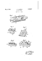
- Fig. 1 is ya perspective vie-W of one 1.611,11-r ⁇ bodiment of the invention illustrated in eenr-A nection with the printing roller element of a conventional form of paper printing Inachine;
- F 2 is a showing yof a modified embodimenst of the invention insofar ⁇ as ,the print- ⁇ 09 Y ing surface is concerned and illustrated in connection with a hand manipulated implement 0r tool; Y v .i
- Fig. 3 is, an enlarged detail view .of one of the filled design forming frames shown in 05 Fig. 1; ⁇ i
- Figa is an enlarged, transverse sectionf taken through one Yof the de signvf-rames of Fig. 1 and showing approxi-mately .the construction as Vtaken on the line .of this 'N figure-5 and Fig. 5 is a similar view showing a different form of Vframe and its contents and taken on the line 5 5 of Fig. 1.
- FIG. 1 Refer-ring .to the gd-'sclosure in Fig. 1, there 7.5 is shown, as part of a printing machine',fa. wooden roller 10 mountedon ⁇ a driving shaft 11 and which roller 1 0 is covered by a. cy.-4 lind-rical sleeve 12 constituting lone .physical embodiment of the invention.
- a wooden support 13 in this case ,sho-write be a flat ⁇ block provided with :a 'handle 14 and suitably fastened to which is a sheet .of
- the sleeve 12 is formed .of soft or semisoft rubber, paper or other suitable mold.- 9.9. able material, as is also the block 15 ,and in both Figs. 1 and 2 there isrshownI printing studs or projections 16 formed integral-with the support 12 or 15 as the case may be and having outer faces 17 which l.may be flat but 9,5 preferably are tangent to the ysurface .ofma cylinder enclosing the cylinder 12' in the case of Fig. 1, or parallel to the top of .the block 15Yas in Fig. 2.
- These projections 16 may be'vrelatively long compared to their 100 other dimensions or may be short as in some of the projections 16 but in either case,
- the printing roller with a plurality of spaced apart projections of th'is type capable of relative movement as they are brought into engagement, with the surface under treatment thus forming a peculiarly appearing. distortable character of stippled surface.
- the projections may be grouped to form blotches or irregular groups of designs or to form some more positively defined design as may be desired.
- the base portion 12 be formed of some Vmaterial 18 (Fig. 4), such for instance'as wood or other material into which could be driven a brass frame 19, or it may be some rugged moldable material such as the hard rubber 2O (Fig. 5) into which the brass frame 19 might beset during the molding operation.
- Vmaterial 18 Fig. 4
- Fig. 4 the frames are shownincorporated into the softvrubber sleeve ⁇ 12 so that there is disclosed in the severel figures the concept of mounting the frame 19 more or less rigidly in different characters of supporting structure.
- the frame 19 may be of any desired configuration to give the required outline of designand is formed preferably of an endless strip of thin brass strip which can be bent'easily into the desired outline.
- the brass frame is driven into the wood or other support, as is shown in Fig. 4, it must of course have sufficient mass and rigidity so as not to be distorted in the'- act of hammering it into place, but where this frameis otherwise fastened as by molding it in place as shown in Figs. 1 and 5, an extremelyv thin gauge of brass strip may be utilized and this would be particularly true where it was desired to use the exposed edge of the frame Vas part of the printing surface as would be the case in the showing in Fig. 4.
- the brass frame is filled with a material capable of receiving color from the color rollers or equivalent color supplying agency and to apply the color to the surface under treatment.
- Fig. 4 is filled with a. body of felt or paper 21 which has been tamped into position or otherwise compressed, level with the top edge 22 ofthe frame so-as to provide within the design outlined by the frame a felt or soft material printing surface 23. It is obviously within the scope of the disclosure to position within the frame 19 other forms of printing material such for instance as sponge rubber, fabric, paper and the, like, the frame providing rigidity of outline and thus preventing the spreading of the more or less loosely packed material 21. In the showing in Fig. 5, the.
- the frame 19 in agency is in the form of a block 24;' of moldl able material such as soft rubber or paper.
- This comprises a massive base vportion 25 which extends above the top edge of the outlining frame 19 and from the top surface 26 extends one or more printing projections 27.
- the top surfaces 28 of these'projections provide printing surfaces and may be of various ⁇ forms and are so grouped both with reference to each other and with reference to vthe corresponding projections at. other parts of the entire printing surface to give the desired design and appearance to the entire kprinted surface.
- the printingV surface be defined by a depression 29 forming a suction cup outlined by a thin edge 30 which may be of circular form as shown in Fig. 3, ofv triangular form as shown at 31 in Figs?) and 5,.or of'. any other geometric or irregular form'which may be selected by the artist in designingthe appearance of the finished surface.
- the printing surfaces may be Vmolded in one operation to give the all-rubberform shown in Fig. 2 or it may be made up into sheets which are cut to size and conventionally fastened to the supports l0 or y13.
- the printing surfaces herein disclosed may be duplicated and placed in proper position on the several rollers.
- the other printing projections herein disclosed are characterized by their ability to give or distort under pressure and will form a character of design which is more indefinite in outline than is the case where the conventional forms of printing surfaces are used.
- some novel effects have been produced by an artistic grouping of sharply defined lines and areas with the less sharply defined lines and areas capable of being produced by utilizing the flexible soft rubber and similar tips andy projections featured in this disclosure.
- a support a brass frame enclosing a printing area of prescribed design, a layer of felt, packed into said frame and having its exposed side flush with the top edge of said brass frame and ooacting therewith to provide a printing surface, the edge of the frame forming a sharply defined outline to the printed design.
- means forming a printing surface said means including a plurality of spaced apart rubber tits coacting to form a design and a plurality of spaced apart printing projections having printing surfaces defined by felt and coacting with the rubber tits to form a prescribed design.
- a printing roller comprising a wooden roller, a removable attachment secured thereto and including a sleeve fitted over the wooden roller, a plurality of printing projections extending radially from the outer surface of the sleeve, and coacting to form a printing surface, said projections comprising a plurality of easily bendable and compressible tits of moldable material and rigid means spaced from the printing surface for reinforcing the jointure between these projections and the sleeve without materially affecting the character of the elements forming the printing surface to move relative to each other.
- a printing roller comprising a wooden roller, a removable attachment secured thereto and including a sleeve fitted over the wooden roller, a plurality of printing projections extending radially from the outer surface of the sleeve, said projections comprising a plurality of soft or semi-soft eas- New York and State of New York this 28th day of August, A. D. 1930. Y
Landscapes
- Engineering & Computer Science (AREA)
- Manufacturing & Machinery (AREA)
- Health & Medical Sciences (AREA)
- General Health & Medical Sciences (AREA)
- Toxicology (AREA)
- Printing Methods (AREA)
Description
May 9, 1933- c. G'. HAMPsoN 1,908,237.
PRINTING ROLLER Filed Oct. 5, 1950 INVENTOR ATTRNEY Patented May 9, 1933 UNITED `STATES CHARLES G. HAMPsoN, or JAMAICA, NEW YORK PRINTING ROLLER.
Appncation med october s, 1930. serial No. 486,147.
The invention relates to an improvement in printing surfaces of the type employed to distribute color in different designs on wall paper, fabrics, metallic surfaces., painted Walls and the like, hereinafter re-V ferred to .collectively as paper.V VIt is a usual practice in the printing. art to canse the paper, fabricor other material to :be printed 19 with sui-table rollers for distributing colorto a printing roller which in turn impresses its design upon the material passed through the machine. In .other cases, it has been known `to utilize hand implements for creating decorative designs and other surfaces on thick Vstructures such as walls and ceilings.
The invention herein disclosed relates parf-.ticularly to the printing surface itself designed for adaptation to both the roller vtype 2Q form .in .either a machine `or in the hand implement and to the Vflat form, and the inven- 'tion particularly features a readily demount-v able and replaceable form of printing surface which may constitute a replacement on the usual printing rollers or on the hand implement .as the case may be land following conventional practices in this respect.
The primary object of the invention is to provide -a Vsimplified form of printing 0 surface which can be easily vand cheaply formed to give any desired design or appeara'nce to the printed Surface and which wilfl :be unusually vrugged and capable of a longer Ylife than is usual with similar known constructions. l
` present invention particularly features the provi-ding of 4a printing surface which will give a mottled, stipp'led, irregular appearance or which will give a design 0 of a vmore regular appearance, and which may contain either sharp or blurred outk linesy as desired.
Various 4other objects and advantages of the invention will be in part obvious from an inspection vof the accompanying drawing ,and in part will be more fully set forth 'm .the following particular description of two forms of mechanism embodying the invent'ion, and the invention also 4consists in certain new and novel features of constructo be passed through a machine provided tion and `combination of parts hereinafter set forth and claimed.'
In .the accompanying drawing;l Fig. 1 is ya perspective vie-W of one 1.611,11-r` bodiment of the invention illustrated in eenr-A nection with the printing roller element of a conventional form of paper printing Inachine;
F 2 is a showing yof a modified embodimenst of the invention insofar `as ,the print-` 09 Y ing surface is concerned and illustrated in connection with a hand manipulated implement 0r tool; Y v .i
Fig. 3 is, an enlarged detail view .of one of the filled design forming frames shown in 05 Fig. 1;` i
Figa is an enlarged, transverse sectionf taken through one Yof the de signvf-rames of Fig. 1 and showing approxi-mately .the construction as Vtaken on the line .of this 'N figure-5 and Fig. 5 is a similar view showing a different form of Vframe and its contents and taken on the line 5 5 of Fig. 1.
Refer-ring .to the gd-'sclosure in Fig. 1, there 7.5 is shown, as part of a printing machine',fa. wooden roller 10 mountedon `a driving shaft 11 and which roller 1 0 is covered by a. cy.-4 lind-rical sleeve 12 constituting lone .physical embodiment of the invention. Referring to Q0 the disclosure `in Fig. 2, there yis shown a wooden support 13, in this case ,sho-write be a flat `block provided with :a 'handle 14 and suitably fastened to which is a sheet .of
molded soft or semi-soft rubber o r paper 815.
15,` vconstitu-ting a printing surface corresponding in function `to the cylindrical surface 12 shown in F ig. L1. i
The sleeve 12 is formed .of soft or semisoft rubber, paper or other suitable mold.- 9.9. able material, as is also the block 15 ,and in both Figs. 1 and 2 there isrshownI printing studs or projections 16 formed integral-with the support 12 or 15 as the case may be and having outer faces 17 which l.may be flat but 9,5 preferably are tangent to the ysurface .ofma cylinder enclosing the cylinder 12' in the case of Fig. 1, or parallel to the top of .the block 15Yas in Fig. 2. These projections 16 may be'vrelatively long compared to their 100 other dimensions or may be short as in some of the projections 16 but in either case,
distinguish from the known forms of rubber faced type Ain that they are easily distortable while in use and will thus impress upon the printedxsurface a different appearance than would be the case if the projections evenfthough made of rubber were so rigid as to be unyielding or substantially so. It is within the scope of the disclosure to provide the printing roller with a plurality of spaced apart projections of th'is type capable of relative movement as they are brought into engagement, with the surface under treatment thus forming a peculiarly appearing. distortable character of stippled surface. The projections may be grouped to form blotches or irregular groups of designs or to form some more positively defined design as may be desired.
YIt is obvious that under some conditions the formation of the projections 16 as integral parts of the soft, semi-soft rubber or paper base portions 12 or 15 would provide a rather weak connection between the projections, especially if they were of material length and easily bendable and are thus liable to become damaged or even broken away from the 'base portion under-the action of the high pressures used in printing operations. It ,is accordingly suggested hereinthat the base portion 12 be formed of some Vmaterial 18 (Fig. 4), such for instance'as wood or other material into which could be driven a brass frame 19, or it may be some rugged moldable material such as the hard rubber 2O (Fig. 5) into which the brass frame 19 might beset during the molding operation. In the disclosure in Fig. 1, the frames are shownincorporated into the softvrubber sleeve `12 so that there is disclosed in the severel figures the concept of mounting the frame 19 more or less rigidly in different characters of supporting structure. i
The frame 19 may be of any desired configuration to give the required outline of designand is formed preferably of an endless strip of thin brass strip which can be bent'easily into the desired outline. In the event that the brass frame is driven into the wood or other support, as is shown in Fig. 4, it must of course have sufficient mass and rigidity so as not to be distorted in the'- act of hammering it into place, but where this frameis otherwise fastened as by molding it in place as shown in Figs. 1 and 5, an extremelyv thin gauge of brass strip may be utilized and this would be particularly true where it was desired to use the exposed edge of the frame Vas part of the printing surface as would be the case in the showing in Fig. 4.
, In' the formishown in Fig. 4, the brass frame is filled with a material capable of receiving color from the color rollers or equivalent color supplying agency and to apply the color to the surface under treatment. Fig. 4; is filled with a. body of felt or paper 21 which has been tamped into position or otherwise compressed, level with the top edge 22 ofthe frame so-as to provide within the design outlined by the frame a felt or soft material printing surface 23. It is obviously within the scope of the disclosure to position within the frame 19 other forms of printing material such for instance as sponge rubber, fabric, paper and the, like, the frame providing rigidity of outline and thus preventing the spreading of the more or less loosely packed material 21. In the showing in Fig. 5, the. printing For this purpose the frame 19 in agency is in the form of a block 24;' of moldl able material such as soft rubber or paper. This comprises a massive base vportion 25 which extends above the top edge of the outlining frame 19 and from the top surface 26 extends one or more printing projections 27. The top surfaces 28 of these'projections provide printing surfaces and may be of various `forms and are so grouped both with reference to each other and with reference to vthe corresponding projections at. other parts of the entire printing surface to give the desired design and appearance to the entire kprinted surface. f
Instead of the flat printing surface shown at 28 in Fig. 5, it is suggested that the printingV surface be defined by a depression 29 forming a suction cup outlined by a thin edge 30 which may be of circular form as shown in Fig. 3, ofv triangular form as shown at 31 in Figs?) and 5,.or of'. any other geometric or irregular form'which may be selected by the artist in designingthe appearance of the finished surface. v
The printing surfaces may be Vmolded in one operation to give the all-rubberform shown in Fig. 2 or it may be made up into sheets which are cut to size and conventionally fastened to the supports l0 or y13. When a plurality of rollers or blocks lare lio used to impress dierent colors on the printed surface, the printing surfaces herein disclosed may be duplicated and placed in proper position on the several rollers.
It is obvious from this disclosure that a variety of stippled, blotted, mottled, vfine line, coarse line and dotted area a pearances may be given to the printedsur aces. The use of the design forming metal frame herein featured is particularly Valuable in that it can give rigidity and strength to what would otherwise be an extremely delicate andY easily distortable form of printing surface and at the same time there is retained the advantages of suchsurfaces when made of material such as soft, semi-soft rubber or paper.V While the top edge of the'frame as shown in Fig. 4 will give a similarly sharp and denitely defined outline to the printed design, the other printing projections herein disclosed are characterized by their ability to give or distort under pressure and will form a character of design which is more indefinite in outline than is the case where the conventional forms of printing surfaces are used. In the printing of surfaces such as wall paper and fabrics, some novel effects have been produced by an artistic grouping of sharply defined lines and areas with the less sharply defined lines and areas capable of being produced by utilizing the flexible soft rubber and similar tips andy projections featured in this disclosure.
I claim:
l. In a device of the class described, the combination of a support, a brass frame enclosing a printing area of prescribed design, a layer of felt, packed into said frame and having its exposed side flush with the top edge of said brass frame and ooacting therewith to provide a printing surface, the edge of the frame forming a sharply defined outline to the printed design.
2. In a device of the class described, the
l combination of a hollow rigid metal frame and a filler of flexible material in said frame, said filler having a side thereof exposed through the frame to form a printing surface flush with the exposed edge of the frame and said exposed filler surface and the exposed edge of the frame outlining the same forming a printing face.
3. In a device of the class described, means forming a printing surface, said means including a plurality of spaced apart rubber tits coacting to form a design and a plurality of spaced apart printing projections having printing surfaces defined by felt and coacting with the rubber tits to form a prescribed design.
4.' A printing roller comprising a wooden roller, a removable attachment secured thereto and including a sleeve fitted over the wooden roller, a plurality of printing projections extending radially from the outer surface of the sleeve, and coacting to form a printing surface, said projections comprising a plurality of easily bendable and compressible tits of moldable material and rigid means spaced from the printing surface for reinforcing the jointure between these projections and the sleeve without materially affecting the character of the elements forming the printing surface to move relative to each other.
5. A printing roller comprising a wooden roller, a removable attachment secured thereto and including a sleeve fitted over the wooden roller, a plurality of printing projections extending radially from the outer surface of the sleeve, said projections comprising a plurality of soft or semi-soft eas- New York and State of New York this 28th day of August, A. D. 1930. Y
CHARLES G. HAMPSON.
Priority Applications (1)
| Application Number | Priority Date | Filing Date | Title |
|---|---|---|---|
| US486147A US1908237A (en) | 1930-10-03 | 1930-10-03 | Printing roller |
Applications Claiming Priority (1)
| Application Number | Priority Date | Filing Date | Title |
|---|---|---|---|
| US486147A US1908237A (en) | 1930-10-03 | 1930-10-03 | Printing roller |
Publications (1)
| Publication Number | Publication Date |
|---|---|
| US1908237A true US1908237A (en) | 1933-05-09 |
Family
ID=23930785
Family Applications (1)
| Application Number | Title | Priority Date | Filing Date |
|---|---|---|---|
| US486147A Expired - Lifetime US1908237A (en) | 1930-10-03 | 1930-10-03 | Printing roller |
Country Status (1)
| Country | Link |
|---|---|
| US (1) | US1908237A (en) |
Cited By (5)
| Publication number | Priority date | Publication date | Assignee | Title |
|---|---|---|---|---|
| US2905085A (en) * | 1956-11-15 | 1959-09-22 | British Tufting Machinery Ltd | Textile printing |
| US3142082A (en) * | 1961-09-19 | 1964-07-28 | Harwood Robert Bennett | Paint design transfer tool |
| US3817178A (en) * | 1972-02-15 | 1974-06-18 | D Hagen | Apparatus for ornamenting walls and ceilings |
| US5832832A (en) * | 1997-01-14 | 1998-11-10 | Carsel; Dale Anthony | Wall decoration paint applying device |
| US6390801B1 (en) | 1998-01-06 | 2002-05-21 | Steven Dale Smith | Texturing tool |
-
1930
- 1930-10-03 US US486147A patent/US1908237A/en not_active Expired - Lifetime
Cited By (6)
| Publication number | Priority date | Publication date | Assignee | Title |
|---|---|---|---|---|
| US2905085A (en) * | 1956-11-15 | 1959-09-22 | British Tufting Machinery Ltd | Textile printing |
| US3142082A (en) * | 1961-09-19 | 1964-07-28 | Harwood Robert Bennett | Paint design transfer tool |
| US3817178A (en) * | 1972-02-15 | 1974-06-18 | D Hagen | Apparatus for ornamenting walls and ceilings |
| US5832832A (en) * | 1997-01-14 | 1998-11-10 | Carsel; Dale Anthony | Wall decoration paint applying device |
| US5857411A (en) * | 1997-01-14 | 1999-01-12 | Carsel; Dale Anthony | Wall decoration paint applying device |
| US6390801B1 (en) | 1998-01-06 | 2002-05-21 | Steven Dale Smith | Texturing tool |
Similar Documents
| Publication | Publication Date | Title |
|---|---|---|
| US1908237A (en) | Printing roller | |
| US1598538A (en) | Ink pad | |
| US1589665A (en) | Article of manufacture | |
| US1304083A (en) | moore | |
| US1964236A (en) | Printing | |
| US1967444A (en) | Space packing felt | |
| US2631536A (en) | Decorating stamp | |
| US2616368A (en) | Ball marker | |
| US1742363A (en) | Process and machine for manufacturing wall paper and the like | |
| US1323487A (en) | Inking-pad | |
| US2339145A (en) | Embossing method and means | |
| US1753932A (en) | Art of printing | |
| US1589024A (en) | Printing die | |
| US2288860A (en) | Method of surface ornamentation | |
| US1056805A (en) | Process of manufacturing means for simultaneously printing, perforating, and cutting. | |
| US1449545A (en) | Underlay for printing on paper bags and the like and the process of making same | |
| US2292996A (en) | Method of carving duplicate designs | |
| US1643028A (en) | morlan | |
| US204146A (en) | Improvement in marbleizing paper and other fabrics | |
| US2149606A (en) | Dampening roll for lithographing presses | |
| US2095199A (en) | Apparatus for ornamenting paper or the like | |
| US1060893A (en) | Method for producing printing-surfaces. | |
| US847237A (en) | Printing or engraving block. | |
| US1567860A (en) | Marking patterns and the like | |
| US1559928A (en) | Form of plates and rollers to ornament materials |