US1908223A - Safety blade sharpener - Google Patents
Safety blade sharpener Download PDFInfo
- Publication number
- US1908223A US1908223A US288920A US28892028A US1908223A US 1908223 A US1908223 A US 1908223A US 288920 A US288920 A US 288920A US 28892028 A US28892028 A US 28892028A US 1908223 A US1908223 A US 1908223A
- Authority
- US
- United States
- Prior art keywords
- blade
- rollers
- sharpening
- carriage
- frame
- Prior art date
- Legal status (The legal status is an assumption and is not a legal conclusion. Google has not performed a legal analysis and makes no representation as to the accuracy of the status listed.)
- Expired - Lifetime
Links
- 230000000994 depressogenic effect Effects 0.000 description 5
- 230000008093 supporting effect Effects 0.000 description 4
- 238000010276 construction Methods 0.000 description 2
- 241000208202 Linaceae Species 0.000 description 1
- 235000004431 Linum usitatissimum Nutrition 0.000 description 1
- 239000011248 coating agent Substances 0.000 description 1
- 238000000576 coating method Methods 0.000 description 1
- 230000000295 complement effect Effects 0.000 description 1
- 239000002184 metal Substances 0.000 description 1
- 230000000284 resting effect Effects 0.000 description 1
- 238000003466 welding Methods 0.000 description 1
Images


Classifications
-
- B—PERFORMING OPERATIONS; TRANSPORTING
- B24—GRINDING; POLISHING
- B24D—TOOLS FOR GRINDING, BUFFING OR SHARPENING
- B24D15/00—Hand tools or other devices for non-rotary grinding, polishing, or stropping
- B24D15/06—Hand tools or other devices for non-rotary grinding, polishing, or stropping specially designed for sharpening cutting edges
- B24D15/08—Hand tools or other devices for non-rotary grinding, polishing, or stropping specially designed for sharpening cutting edges of knives; of razors
- B24D15/085—Hand tools or other devices for non-rotary grinding, polishing, or stropping specially designed for sharpening cutting edges of knives; of razors with reciprocating whetstones
Definitions
- a blade carrying carriage is moved back and forth for drawing the edges of a razor blade across a hone or a strop.
- pressure between the blade edge and the sharpening device over which it is passed is obtained by frictional engagement between a flat-sided wheel and the surface of a race-way formed in the frame.
- the blade is turned180 during each complete stroke by permitting the wheel r to turn upon its flat side.
- the blade is removed from one side of the carriage and moved to the opposite side of the sharpening device.
- Figure 2 is a side elevational view thereof
- Figure 3 is-a longitudinal sectional view thereof taken along the section line IIIIII of Figure 1;
- Figure 4 is a lon 'tudinal sectional view takep along the section line IV-IV of Fig- Figure 5 is a transverse sectional view taken along the section line V V of Figure 1; t
- Figure 7 is a longitudinal sectional view taken along the section line IVIV of Figure 1, but showing the carriage at the opposite end of the frame from the showing of Figure 4;
- Figure 8 is a sectional view of a portion of the sharpener showing the carriage inits blade releasing portion; 7 t
- Figure 9 is a plan view, partially in section, of a portion'of the sharpener showing the manner of mounting the block supporting the honing and stropping surfaces;
- 1 r p Figure 10 is a diagrammatic view showing the several positions occupied by theblade during its'movement to the right of Figures 1, 2, 4 and 7 of the drawings;
- Figure 11 is a diagrammatic view of the successive positions occupied by the blade during the movement to the left of the several figures;
- Figure 12 is a plan view of a blade holder for apair of razor blades, each having a single cutting edge; t A
- Figure 13 is an edge view thereof.
- Figure 14 is a diagrammatic plan view the holder shown in Figure 12.
- a safety blade sharpener comprises a frame 4 constituted by side plates 6 andiend if? plate 12. It is to be understood, however,
- a sharpening block 8 is rotatably mounted on a shaft 9.
- a carriage 10 is supported by longitudinally extending bars 11 turned upwardly from a base plate 12 that constitutes the bottom of the sharpener.
- the plate 12 is secured by extensions 14 extending through openings 15 in the end plates 7.
- the end plates 7 are, in turn, secured to the side plates 6 by screws 16.
- the side plates 6 are preferably notched, as at 17, for the reception of the end plates 7
- the notches may be formed by pressing the metal of the side plates outwardly or by welding cover plates over openings in the side of the frame.
- the screws 16 extend through the sidewalls and engage the ends of the end plates 7 inserted in the notches 17. As the end plates 7 are held against longitudinal movement in the frame, the bars 11 and plate 12 are held in a rigid position.
- the block 8 carries a stropping surface 18 and a honing surface 19 which are disposed at different distances from the shaft 9 in order that a blade traversing them shall bear against the surfaces at different angles.
- the angle between the edge of the blade and the stropping surface is preferably made slightly steeper than the angle between the edge of theblade and the honing surface by having the honing surface extend outwardly from the axis of the block 8a greater distance than the stropping surface.
- the block 8 is disposed diagonally to the longitudinal axis of the, sharpener to insure that the successive portions of the blade are moved across the sharpening surface in both a longitudinal and a transverse direction.
- the block 8 extends I outwardly through an opening 20 in the that the blades may be passed over the stropping and honing surfaces at the same angles, if desired.
- the shaft 9 is supported by bearings 21 and 22 secured to the inner surfaces of one of the side plates 6 and bars 11.
- the shaft extends outwardly through an opening 24 in the other bar 11 and through an opening 25 in the side plate 6.
- a knurled hand grip 26 is secured to theend of the shaft 9 for turning the shaft.
- the sidewall 6 near the open.
- ing 25 therein is depressed inwardly ofthe frame to protect a portion of the hand grip 26 and to form the bearing 21 for the shaft 9.
- a spring 27 is wound about the shaft 9 between a shoulder 28. formed thereon and the bearing 22.
- the bearing 22 is provided with a notch 29 of V-shape into which a complementary pin 30 carried on the shaft 9 fits.
- theshaft 9 is moved longitudinally to compress the spring and move the pin 30 out of the notch 29.
- the'operator releases the hand grip 26 which permits the spring 27 to expand and draws the opposite end of the pin 30 into the notch 29 for locking the block 8 against accidental turning.
- the carriage 10 comprises a pair of side plates 32 that are connected by a rod 34 and a plat-e 35 that serves as a grip for the operator. Extending forwardly from the side plates 32 are a pair of levers 36 having notches 37 near the outer ends thereof.
- razor blade carrier 38 is mounted in the notches 37.
- the levers 36 are urged in a counter-clockwise direction, as viewed in Figure 3, by a spring 39, one end of which is attached to the adjacent side plate 32.
- the blade carrier 38 is provided with rollers 40 at the opposite ends thereof.
- the carriage 10 is mounted in the sharpener with the plates 32 resting in grooves 41 formed in the bars 11.
- the rollers 40 are urged into engagement with the inner surfaces of the upper inturned edges 42 of the side walls 6 by the action of the springs 39. Accordingly, as the carriage 1-0 is moved back and forth along the sharpener the rollers 40 engage the surfaces of the inturned portions 42 and tend to rotate a blade 44 Carried by the holder 38. i
- the inturned edges 42 of the side plates extend substantially to the rear (left side of Figures 1, 2, 3, 4 and 7) of the sharpener frame. At the front edge they are cut away to provide a space for inserting the blade carrier into the. notches 37. Forward movement of the carriage 10 to free the carrier38 from the notches 37 under normal operation is prevented by stops 45 extending upwardly throughthe grooves 41.
- the stops 45 are constituted by the bent up ends of a loop 46, the central portion 47 of which extends outwardly through an opening 48 in the end plate 7 of the frame.
- the loop 46 is pivotally mounted, as at 49, in the bars 11 so that upon counter-clockwise movement of the central portion 47 the stops 45 are depressed beneath the surface of the grooves 41 to permit the carriage 10 to slide forward to stop shoulders 45 far enough to uncover the notches 37 frombeneath the inturned portions 42 of the side plates.
- the blade carrier 38 is then removed.
- the stops 45 are urged into position to engage the plates 32 by a spring 50 extending between the bars 11 and bearing against the upper surface of the loop 46.
- rollers 54 For turning the blade at the forward end of its travel, a pair of rollers 54 are yieldingly mounted on a shaft 55.
- the shaft is movable vertically in slots 56 in the bars 11.
- Springs 57 mounted on the outer surfaces of the bars 11 urge the rollers 54 upwardly into engagement with the blade.
- the surface of the rollers 51, 52 and 54 are covered with a soft coating, such as rubber, although it is to be understood that hard sur faced rollers may be used if desired.
- FIG. 10 the movement of a blade during a complete sharpening stroke is illustrated diagrammatically.
- the blade rests on the roll-er 52 in the position A of Figure 10.
- the round rollers 40 turn the blade in a counter-clockwise manner to position B. Further turning movement is resisted by the roller 52 and the blade is carried forward over the roller and ,,.along the sharpening surface of the block 8 at a uniform angle, indicated by positions 0 of Figure 10.
- the blade is urged against the sharpening surface with a yielding pressure by reason of the tendency of the round rollers 40 to turn.
- the blade Near the end of the forward stroke the blade is lifted from the sharpening surface by the roller 51, as shown in position D. After the blade passes over the roller 51, it turns in a counter-clockwise direction into position E, where it engages the roller 54. The rollers 54 are depressed against the springs 57 as the blade slides over them in the position F. After the blade has passed the rollers 54 it turns into position G.
- the blade leaves the roller 51 in the position K. After passing the roller 51 the blade traverses the sharpening surface in parallel positions shown by L. At the end of the travel, the blade again engages the roller 52 which returns the blade to position A, although the blade surface has been turned through 180 from the original position A. Accordingly, the several edges of the blade are sharpened during two successive forward and backward movements of the carriage 10.
- Blades 58 are provided with notches 59 near their back edges.
- a pair of blades 58 isembodied without departing from the scope V of the appended claims.
- a blade sharpening device comprising a frame, sharpening means mounted therein, a carriage reciprocable in said frame for moving a blade across the sharpening means, rolls on each side of said sharpening means for supporting the leading edge of a blade in the carriage as it passes off the sharpening means, and a pair of rolls for engaging the blade adjacent its ends toturnthe blade after it has left the sharpening means and said supporting rolls.
Landscapes
- Engineering & Computer Science (AREA)
- Mechanical Engineering (AREA)
- Finish Polishing, Edge Sharpening, And Grinding By Specific Grinding Devices (AREA)
Description
y 1933. B. CUDDY 1,908,223
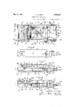
7 SAFETY BLADE SHARPENER Filed June 28, 1928 3 Sheets-Sheet 1 J5 40 30 2 I 6 4 JZ /1 KJVENTOR 1z12 278 15.9 5 5 17 flax/QM,
y 9, 1933. 1.. B. CUDDY 1,908,223
SAFETY BLADE S HARPENER Filed June 28, 1928 3 Sheets-Sheet 2 y 1933- L. B. gummy 1,908,223
SAFETY BLADE SHARPENER Filed June 28, 1928 3 Sheets-Sheet 5 Patented May 9, 1933 UNITED STATES LOF'IUS B. GUDDY, or snwIcKLEY, PENNSYLVANIA, ASSIGNOR or ONE-HALF KINLEY J. TENER, or PITTSBURGH, PENNSYLVANIA PATENT OFFICE SAFETY BLADE SHARPENER Application filed .Tune 28,
the structure of the Barsch patent, a frame.
is provided in which a blade carrying carriage is moved back and forth for drawing the edges of a razor blade across a hone or a strop. In the Barsch structure, pressure between the blade edge and the sharpening device over which it is passed is obtained by frictional engagement between a flat-sided wheel and the surface of a race-way formed in the frame. The blade is turned180 during each complete stroke by permitting the wheel r to turn upon its flat side. To change the blade from a honing to a stropping operation, or vice versa, the blade is removed from one side of the carriage and moved to the opposite side of the sharpening device.
In my copending application, Serial No. 274,218 filed May 1,1928, I have shown and described a blade sharpener in which circular wheels and a plurality of resiliently mounted rollers are provided for turning the blade. Provision is further made for performing the honing and stropping operation on one side of the'frame and without removing the blade from the carriage. Honing and stropping surfaces are formed on opposite faces of a block that is detachably mounted in the framefor being reversed relative thereto.
In the present invention greater. ease for transferring from the honing to the stropping operation is obtained by reversibly mounting the block carrying the honing and stropping surfaces within the frame in such manner that the block need not be removed from the frame during the transfer. Provision is made for locking the block against accidental reversal. I also provide further 1928. Serial No. 288,520.
improvements in certain of the details of construction shown and described in my prior application, as are hereinafter more fully set forth. 7 v
The accompanying drawings illustrate a present preferred embodiment of thevinvention, in which- 5 Figure 1 is a plan View of a sharpener embodyingmy invention;
Figure 2 is a side elevational view thereof;
Figure 3 is-a longitudinal sectional view thereof taken along the section line IIIIII of Figure 1;
Figure 4 is a lon 'tudinal sectional view takep along the section line IV-IV of Fig- Figure 5 is a transverse sectional view taken along the section line V V of Figure 1; t
Figure 6 is a plan view of the carriage for the blade;
Figure 7 is a longitudinal sectional view taken along the section line IVIV of Figure 1, but showing the carriage at the opposite end of the frame from the showing of Figure 4; I
Figure 8 is a sectional view of a portion of the sharpener showing the carriage inits blade releasing portion; 7 t
Figure 9 is a plan view, partially in section, of a portion'of the sharpener showing the manner of mounting the block supporting the honing and stropping surfaces; 1 r p Figure 10 is a diagrammatic view showing the several positions occupied by theblade during its'movement to the right of Figures 1, 2, 4 and 7 of the drawings;
Figure 11 is a diagrammatic view of the successive positions occupied by the blade during the movement to the left of the several figures;
Figure 12 is a plan view of a blade holder for apair of razor blades, each having a single cutting edge; t A
Figure 13 is an edge view thereof; and
Figure 14 is a diagrammatic plan view the holder shown in Figure 12.
Referring to Figuresl to 4 inclusive, and Figure 7, a safety blade sharpener comprises a frame 4 constituted by side plates 6 andiend if? plate 12. It is to be understood, however,
The screws 16 extend through the sidewalls and engage the ends of the end plates 7 inserted in the notches 17. As the end plates 7 are held against longitudinal movement in the frame, the bars 11 and plate 12 are held in a rigid position.
The block 8 carries a stropping surface 18 and a honing surface 19 which are disposed at different distances from the shaft 9 in order that a blade traversing them shall bear against the surfaces at different angles. The angle between the edge of the blade and the stropping surface is preferably made slightly steeper than the angle between the edge of theblade and the honing surface by having the honing surface extend outwardly from the axis of the block 8a greater distance than the stropping surface. The block 8 is disposed diagonally to the longitudinal axis of the, sharpener to insure that the successive portions of the blade are moved across the sharpening surface in both a longitudinal and a transverse direction. The block 8 extends I outwardly through an opening 20 in the that the blades may be passed over the stropping and honing surfaces at the same angles, if desired.
The shaft 9 is supported by bearings 21 and 22 secured to the inner surfaces of one of the side plates 6 and bars 11. The shaft extends outwardly through an opening 24 in the other bar 11 and through an opening 25 in the side plate 6. A knurled hand grip 26 is secured to theend of the shaft 9 for turning the shaft. The sidewall 6 near the open.-
Referring to Figures 1 and 9, a spring 27 is wound about the shaft 9 between a shoulder 28. formed thereon and the bearing 22. The bearing 22 is provided with a notch 29 of V-shape into which a complementary pin 30 carried on the shaft 9 fits. For turning the shaft 9 and block 8, which is secured thereto by a pin 31, theshaft 9 is moved longitudinally to compress the spring and move the pin 30 out of the notch 29. Afterthe block is turned 180 the'operator releases the hand grip 26 which permits the spring 27 to expand and draws the opposite end of the pin 30 into the notch 29 for locking the block 8 against accidental turning.
The carriage 10 comprises a pair of side plates 32 that are connected by a rod 34 and a plat-e 35 that serves as a grip for the operator. Extending forwardly from the side plates 32 are a pair of levers 36 having notches 37 near the outer ends thereof. A 4
The carriage 10 is mounted in the sharpener with the plates 32 resting in grooves 41 formed in the bars 11. The rollers 40 are urged into engagement with the inner surfaces of the upper inturned edges 42 of the side walls 6 by the action of the springs 39. Accordingly, as the carriage 1-0 is moved back and forth along the sharpener the rollers 40 engage the surfaces of the inturned portions 42 and tend to rotate a blade 44 Carried by the holder 38. i
The inturned edges 42 of the side plates extend substantially to the rear (left side of Figures 1, 2, 3, 4 and 7) of the sharpener frame. At the front edge they are cut away to provide a space for inserting the blade carrier into the. notches 37. Forward movement of the carriage 10 to free the carrier38 from the notches 37 under normal operation is prevented by stops 45 extending upwardly throughthe grooves 41. The stops 45 are constituted by the bent up ends of a loop 46, the central portion 47 of which extends outwardly through an opening 48 in the end plate 7 of the frame. The loop 46 is pivotally mounted, as at 49, in the bars 11 so that upon counter-clockwise movement of the central portion 47 the stops 45 are depressed beneath the surface of the grooves 41 to permit the carriage 10 to slide forward to stop shoulders 45 far enough to uncover the notches 37 frombeneath the inturned portions 42 of the side plates. The blade carrier 38 is then removed. The stops 45 are urged into position to engage the plates 32 by a spring 50 extending between the bars 11 and bearing against the upper surface of the loop 46.
Sustaining rollers 51 and 52-are mounted in upturned flanges onthe plate 12 in a position to lift the blade from the inner surface of the block 8 as the blade is about to leave the surface at the ends of its forward and backward directions of travel, respectively. By lifting the blade from the sharpening surface before the blade has reached the end of the sharpening surface, all tendency for the blade to slide from the sharpening surface at an angle other than the sharpening angle is prevented.
For turning the blade at the forward end of its travel, a pair of rollers 54 are yieldingly mounted on a shaft 55. The shaft is movable vertically in slots 56 in the bars 11. Springs 57 mounted on the outer surfaces of the bars 11 urge the rollers 54 upwardly into engagement with the blade. The surface of the rollers 51, 52 and 54 are covered with a soft coating, such as rubber, although it is to be understood that hard sur faced rollers may be used if desired.
Referring to Figures 10 and 11, the movement of a blade during a complete sharpening stroke is illustrated diagrammatically. At the end of the rear stroke, the blade rests on the roll-er 52 in the position A of Figure 10. As soon as forward movement starts, the round rollers 40 turn the blade in a counter-clockwise manner to position B. Further turning movement is resisted by the roller 52 and the blade is carried forward over the roller and ,,.along the sharpening surface of the block 8 at a uniform angle, indicated by positions 0 of Figure 10. During this movement the blade is urged against the sharpening surface with a yielding pressure by reason of the tendency of the round rollers 40 to turn. Near the end of the forward stroke the blade is lifted from the sharpening surface by the roller 51, as shown in position D. After the blade passes over the roller 51, it turns in a counter-clockwise direction into position E, where it engages the roller 54. The rollers 54 are depressed against the springs 57 as the blade slides over them in the position F. After the blade has passed the rollers 54 it turns into position G.
On the return stroke illustrated in Figure 11, the blade is initially in position G.
Backward movement of the carriage 1O turns the blade in a clockwise direction into position H where it engages the rollers 54. However, the point of tangency between the rollers 54 and the plate is below the center line of the rollers so that the rollers are not initially depressed by pressure from the blade but resist the blade pressure sufficiently to insure that the blade has turned through substantially 180 before it again engages the roller 51 in position 1. After the blade has been turned a sufficient amount by the rollers 54 and after the point of tangency between the rollers 54 and the blade has moved about the axis of the rollers, the rollers are depressed as shown in position J. The blade is turned in a clockwise direction by the movement of the rollers 40 along the surfaces 42 of the side plates. Accordingly, the blade leaves the roller 51 in the position K. After passing the roller 51 the blade traverses the sharpening surface in parallel positions shown by L. At the end of the travel, the blade again engages the roller 52 which returns the blade to position A, although the blade surface has been turned through 180 from the original position A. Accordingly, the several edges of the blade are sharpened during two successive forward and backward movements of the carriage 10.
Referring to Figures 12 to 14, inclusive, I have shown a holder for sharpening sing1eedged blades of well-known construction. Blades 58 are provided with notches 59 near their back edges. A pair of blades 58 isembodied without departing from the scope V of the appended claims.
I claim:
1. A blade sharpening device comprising a frame, sharpening means mounted therein, a carriage reciprocable in said frame for moving a blade across the sharpening means, rolls on each side of said sharpening means for supporting the leading edge of a blade in the carriage as it passes off the sharpening means, and a pair of rolls for engaging the blade adjacent its ends toturnthe blade after it has left the sharpening means and said supporting rolls.
2. A blade sharpening device comprising a frame, sharpening means mounted therein, a reciprocable carriage for moving a blade back and forth across said sharpening means, rolls on both sides of said sharpening means adjacent opposite sides of said frame for engaging one end of the leading edge of a blade in said carriage for support ing it afterthe end of the blade has moved away from said sharpening means.
my hand.
LOFTUS B. CUDDY.
Priority Applications (1)
| Application Number | Priority Date | Filing Date | Title |
|---|---|---|---|
| US288920A US1908223A (en) | 1928-06-28 | 1928-06-28 | Safety blade sharpener |
Applications Claiming Priority (1)
| Application Number | Priority Date | Filing Date | Title |
|---|---|---|---|
| US288920A US1908223A (en) | 1928-06-28 | 1928-06-28 | Safety blade sharpener |
Publications (1)
| Publication Number | Publication Date |
|---|---|
| US1908223A true US1908223A (en) | 1933-05-09 |
Family
ID=23109233
Family Applications (1)
| Application Number | Title | Priority Date | Filing Date |
|---|---|---|---|
| US288920A Expired - Lifetime US1908223A (en) | 1928-06-28 | 1928-06-28 | Safety blade sharpener |
Country Status (1)
| Country | Link |
|---|---|
| US (1) | US1908223A (en) |
Cited By (1)
| Publication number | Priority date | Publication date | Assignee | Title |
|---|---|---|---|---|
| US2729922A (en) * | 1952-08-26 | 1956-01-10 | Ciniglio Ignace | Sharpening apparatus for razor blades |
-
1928
- 1928-06-28 US US288920A patent/US1908223A/en not_active Expired - Lifetime
Cited By (1)
| Publication number | Priority date | Publication date | Assignee | Title |
|---|---|---|---|---|
| US2729922A (en) * | 1952-08-26 | 1956-01-10 | Ciniglio Ignace | Sharpening apparatus for razor blades |
Similar Documents
| Publication | Publication Date | Title |
|---|---|---|
| US2124646A (en) | Knife sharpening device | |
| US4630409A (en) | Device for finishing the edges of skis | |
| GB2168275A (en) | Knife sharpeners | |
| US1908223A (en) | Safety blade sharpener | |
| US1966426A (en) | Combined safety razor and sharpening device | |
| US1826410A (en) | Combined safety razor and sharpening mechanism | |
| US2565281A (en) | Razor and sharpener therefor | |
| US2768486A (en) | Multiple band saw honing mechanism | |
| US1954259A (en) | Shaving device | |
| US1905331A (en) | Combined safety razor and sharpening device | |
| US2729989A (en) | Safety razor blade sharpener | |
| US1935079A (en) | Safety blade sharpener | |
| US1910305A (en) | Sharpening apparatus for razor blades | |
| US1881702A (en) | Razor blade sharpener | |
| US1392701A (en) | Razor-blade sharpener | |
| US1569213A (en) | Razor-blade sharpener | |
| US1399241A (en) | Device for sharpening the blades for safety-razors | |
| US1729722A (en) | Self-stropping razor | |
| US764574A (en) | Safety-razor. | |
| US1920347A (en) | Razor blade sharpener | |
| GB138265A (en) | A new or improved device for sharpening safety razors | |
| GB191315964A (en) | Machines for Sharpening Razors. | |
| US1441536A (en) | Stropper | |
| US2113299A (en) | Razor sharpener | |
| US1845580A (en) | Razor stropping apparatus |