US1908117A - Apparatus and method for handling fluent materials - Google Patents
Apparatus and method for handling fluent materials Download PDFInfo
- Publication number
- US1908117A US1908117A US350561A US35056129A US1908117A US 1908117 A US1908117 A US 1908117A US 350561 A US350561 A US 350561A US 35056129 A US35056129 A US 35056129A US 1908117 A US1908117 A US 1908117A
- Authority
- US
- United States
- Prior art keywords
- chamber
- screw
- conveyor
- housing
- pressure
- Prior art date
- Legal status (The legal status is an assumption and is not a legal conclusion. Google has not performed a legal analysis and makes no representation as to the accuracy of the status listed.)
- Expired - Lifetime
Links
- 239000000463 material Substances 0.000 title description 81
- 238000000034 method Methods 0.000 title description 5
- 239000004519 grease Substances 0.000 description 18
- 239000000314 lubricant Substances 0.000 description 17
- 230000001050 lubricating effect Effects 0.000 description 4
- 230000003247 decreasing effect Effects 0.000 description 3
- 238000003825 pressing Methods 0.000 description 3
- 238000005266 casting Methods 0.000 description 2
- 238000010276 construction Methods 0.000 description 2
- 230000003467 diminishing effect Effects 0.000 description 2
- 239000002184 metal Substances 0.000 description 2
- 230000004048 modification Effects 0.000 description 2
- 238000012986 modification Methods 0.000 description 2
- OHYPPUOVSUINHM-UHFFFAOYSA-N 4-(methylamino)phenol;sulfuric acid Chemical compound OS(O)(=O)=O.CNC1=CC=C(O)C=C1 OHYPPUOVSUINHM-UHFFFAOYSA-N 0.000 description 1
- 208000036366 Sensation of pressure Diseases 0.000 description 1
- 238000013019 agitation Methods 0.000 description 1
- 230000009172 bursting Effects 0.000 description 1
- 230000006835 compression Effects 0.000 description 1
- 238000007906 compression Methods 0.000 description 1
- 239000000470 constituent Substances 0.000 description 1
- 239000010730 cutting oil Substances 0.000 description 1
- 230000007423 decrease Effects 0.000 description 1
- 230000000694 effects Effects 0.000 description 1
- 230000005484 gravity Effects 0.000 description 1
- 239000002917 insecticide Substances 0.000 description 1
- 238000004898 kneading Methods 0.000 description 1
- 239000007788 liquid Substances 0.000 description 1
- 238000004519 manufacturing process Methods 0.000 description 1
- 239000000203 mixture Substances 0.000 description 1
- 239000003973 paint Substances 0.000 description 1
- 229940102098 revolution Drugs 0.000 description 1
- 238000005507 spraying Methods 0.000 description 1
- 239000000126 substance Substances 0.000 description 1
- 239000002699 waste material Substances 0.000 description 1
- -1 whitewash Substances 0.000 description 1
- 238000010626 work up procedure Methods 0.000 description 1
Images


Classifications
-
- F—MECHANICAL ENGINEERING; LIGHTING; HEATING; WEAPONS; BLASTING
- F16—ENGINEERING ELEMENTS AND UNITS; GENERAL MEASURES FOR PRODUCING AND MAINTAINING EFFECTIVE FUNCTIONING OF MACHINES OR INSTALLATIONS; THERMAL INSULATION IN GENERAL
- F16N—LUBRICATING
- F16N13/00—Lubricating-pumps
Definitions
- Thegrease is forced into the cylinder of the booster pump by air lpressure from the compressor. or gravity flow or sucf tion, and frequently such devices become air bound because the air Works its Way through and past the grease and into the booster pump. Furthermore, they are frequently rendered inoperative or ineiiicient because 40 'foreign substances become lodged in the valve seats, interfering- With the proper func# tioning of the valves. Also, because of structural complications, the cost of manufacture of such prior devices has been comparatively high.
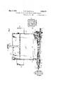
- FIG. 1 is a side elevation of the complete apparatus in a portable form
- Fig. 5 is a longitudinal vertical section-O through the pressure chamber, showing the mechanism therein, certain parts being shown in elevation;
- a cover 23 as Ishown is centrally apertured for the passage of a gauge rod 24, the top of which is finished with a sturdy handle 25 of the conveying .so that the cover and a follower plate 26V4 are always removed together.
- This plate is a heavy piece of metal, with the gauge rod 24 secured to its center.
- the gauge rod may be conveniently graduated in pounds or othe ise, as most desirable.
- the pressure chamber 33 forms a continuation of the passage 31 within the base casting 14, which projects forward somewhat.
- the pressure chamber is capped by an end plate 45 bolted to the forward end of the lubricant chamber 33 and carries within it the pressure means which are shown in detail in Fig. 5, or some alternative form of such means.
- the flexible conduit 16, fastened on the outlet connection 46, conveys grease under pressure to a nozzle 47 which is adapted for engagement with the grease fittings on an automobile or other machine.
- the nozzle includes a valve 47 and motor control switch 47 the latter being connected to the motor 13 by a flexible conduit 16 here shown as fastened to the conduit 16.
- cording to the nature of the material to be handled.
- a wiper mechanism for removing grease from the forward surface of the screw 48 and for passing it to the discharge conduit is reciprocally mounted in a longitudinal bore 54 which extends from the front of the pressure chamber through the cap 45. This bore is parallel to but below the axis of the feed screw.
- the plunger and wiper mechanism is held up against the thread face of the screwf48 by a follower spring 55 which in the present embodiment extends forward of the pressure chamber for some distance and is housed in a cap 56.
- the wiper and plunger may be made either integral of built up.
- a convenient two-piece form is shown in detail in Fig. 6, and comprises a short cylindrical plunger 57, the end 58 of which may be slightly convex to clear the screw.
- a straight longitudinal bore ⁇ 59 goes part way into the plunger parallel to the axis but olf center.
- the forward part of one side of the plunger is flattened, as indicated at 60, to allow passage of grease into the bore 54.
- a port 61- connects the bore 59 with the flat face 60.
- the wiper element may conveniently be in the form of a U-shaped yoke having a square edge 62 across the bottom, and legs 62 engaging slots in the sides of the plungrer.
- the edge 62 bears against the threads of the pressure screw 48, and the legs 62 are guided in vslots formed by the gap between the edges 63 of two semi-cylindrical liner sections which make a sliding fit with the plunger 57.
- the feed channel is closed by/a member 130 having a stationary wiper 131 which may preferably'be formed' integrally therewith.
- the rear end of the feed screw 132. is reciprocably connected, as at 133, with a rotatable power shaft 134, and the rear end of the feed screw is surrounded by a compression spring 135 to move the feed screw forward after' the front ⁇ of the thread passes ofi' the wiper.
- the feed passage 136 is closed on top to t the conveyor tightly for some distance back from the delivery end, as indicated at 137 Itis believed that the operation of our apparatus will be suiciently apparent from the foregoing description, so that only a brief review is now necessary.
- the reservoir 12 being loaded, for example, with grease, the follower plate 26 will rest on top of the grease, and just below the hooks on the upper ends of the rods 19, Fig. 2.
- the power lead 17 being connected to a power or lighting circuit the operator applies the nozzle 47 to a lubricant fitting, opening the valve 47 and closing the switch 47, thus starting the motor 13 and causing the feed screw 32 to rotate.
- Grease is thus drawn into the space 35 and thereby given a mixing or kneading action while being drawn into the screw, thus reincorporating any constituents which may have become separated'.
- the feed screw carries the grease to the pressure mechanism, where it is operated upon according to the nature of the particular type of mechanism employed as hitherto described in detail.
- the pressure mechanism forces it through the hose 16 to the nozzle 47 and so to the point of delivery.
- the valve closes and the switch opens, thus cutting oil'l the iow of grease and also stopping the supply.
- a screw conveyor for causing agitation of said material and imparting spiral translatory movement thereto, and means coacting with said conveyor to remove a portion of the material therefrom and simultaneously subject it to increased pressure.
- Means for feeding plastic material by application of continuous pressure comprising in combination, a screw conveyor, means for rotating the conveyor, a housing for the conveyor. means to subject the mater1al to pressure including a wiper to remove the material from the conveyor and pocket it between the end turn of the screw and the wiper, thereby subjecting it to squeezing ac@ tion.
- A. force feed lubricator comprising 1 n combination a reservoir, a passage of approximately cylindrical cross section across the bottom of said reservoir, said passage being open at the top only to said reservoir, a helical conveyor operating in said passage, a pressure chamber at the end of said passage, means in said chamber for applying pressure to lubricant conveyed thereto by said s crew conveyor, said means comprising a hellx of larger'R4 diameter than said conveyor and of a single convolution, an annular groove 1n which the outer end of said helix travels, and a wiper positoned for longitudinal reciprocation in the path of said helix and engagmg the end thereof to entrap and exert pressure upon the material.
- a force feed lubricator comprlslng 1n Vcombination a reservoir, a passage of approximately cylindrical cross section across the bottom of saidlreservoir, said passage being open at the top only to said reservoir, a helical conveyor operating in said passage, a pressure chamber at the end of said passage, means in said chamber for applying pressure to lubricant conveyed thereto by said screw conveyor, said means comprising a helix of larger diameter than said conveyor and ber adapted to reciprocate. in said bore and carrying said wiper, a spring in said bore urging said member towards the face of the helix, a lubricant passage through said cylindrical member into said bore and a second lubricant passage from said bore, a bys pass also leading away from said bore, and
- a lubricating device in combination vwith a container, screw-propulsion means for removal of lubricant from said container and a booster mechanism associated with said screwk and operated by the threads of the screw.
- screw means for moving a material and a booster mechanism for increasing pressure upon the material associated with the screw and operated by the threads of the screw.
- a convolute conveyor for moving a material, means operable by a convolution of the conveyor for increasing pressure on the material.
- a reservoir for iuent materials a substantially cylindrical channel at the bottom of the reservoir, a screw .rotatable in said channel for moving a material therethrough, a booster operated by the last convolution of said screw adaptedV to remove the material from the screw and subject the same to increased ressure.
- a device for dispensing fluent materials a housing, a chamber in the housing, a rotatable 4convolute conveyor for moving a material disposed in the housing extending into the chamber, a booster co-operable with said conveyor extending into the chamber,
Landscapes
- Engineering & Computer Science (AREA)
- General Engineering & Computer Science (AREA)
- Mechanical Engineering (AREA)
- Processing And Handling Of Plastics And Other Materials For Molding In General (AREA)
Description
May 9, 1933.AI K. s. CLAPP Er AL 1,908,117
APPARATUS AND METHOD FOR HANDLING FLUENT MATERIAL f Filed March 28, 1929 5 sheets-sheet 1` AT ORNEY May 9; 1933- K. s. cLAPP Er AL 1,908,117
` APPARATUS ANDl METHOD FOR HANDLING FLUET MATERIALS Filed Maron 28. 1929 s sheets-sheet 2 INVENTORS 5. CLJ/P 00ans H. E/clrfmrf-- ATTORNEY M HHTH# May 9, 1933. A v vK CLAVPP ET AL 1,908,117
APPARATUS AND METHOD FOR HANDLING FLUENT MATERIALS Filed March 2s, 19:29 s sheets-sheet :s
INVENTORS /E/vmsT/f 5. CL4/P BY Manowar H E/c/fffoFF d? www ATTORNEY Patented May 9, 1933 KENNETH S..CLAJ?P AND THEODORE H. EICQKHOFF, OF CLEVELAND, OHIO APPARATUS AND METHGD FOR HANDLING FLUENT MATERIALS Application led March 28, 1929. Serial No. 350,561.. j
This invention, in its broader aspects, relates to apparatus and a method for moving fluent materials in situations where the nal delivery must be under considerable pressure. In certain embodiments it is of particular value in the handling of plastic compositions, although not inapplicable to liquids, and has among its objects the provision of apparatus of this nature which will 1o be simple in construction, durable and dependable in service, capable of being economically built and operated, and a substantial advance in the art.
TWhile the embodiment herein shown as the preferred form is described with particular reference'to use as a lubricating unit with a self-contained source of supply, for apply ing grease or other heavylubricants to ma-l chine parts in automobile service stations, 2o factories and the like, it is to be understood that such restricted description is resorted to for convenience and' that the principles of the invention are of broader scope and are adaptable for use in other fields. Apparatus of this general type, heretofore available has embodied air compressors; booster pumps, and valves. assembled to gether in a unit by which the grease is delivered through a flexible hose to the ma 3c chine parts to be lubricated, but such devices have given rise to serious objections for several reasons. Thegrease is forced into the cylinder of the booster pump by air lpressure from the compressor. or gravity flow or sucf tion, and frequently such devices become air bound because the air Works its Way through and past the grease and into the booster pump. Furthermore, they are frequently rendered inoperative or ineiiicient because 40 'foreign substances become lodged in the valve seats, interfering- With the proper func# tioning of the valves. Also, because of structural complications, the cost of manufacture of such prior devices has been comparatively high. These and other objectionable features of the prior art are overcome by the present invention. Y
The present application is a continuation in part of pending application, Serial No. tl, filed August 21, 1928, by Kenneth S..
app. v
Specifically, the invention as hereinafter described contemplates two-stagemeans for moving lubricant material, the first stage of such means including a conveying screw rotatable in a housing at the bottom of a reservoir, this screw being associated with the apparatus of the second stage; which applies additional force whereby the lubricant is driven to its destination. For convenience 60 the apparatus for accomplishing the first stage is termed feeding means, and that for the second stage is called presure means, although some latitude is necessary in the interpretation of these terms, for the reason that certain of the elements of our invention may be common to both stages.
When used asa lubricator our invention may be conveniently constructed in the form of a lubricant reservoir the bottom of which 70 constitutes a housing for the feeding and pressure means. Thisreservoir bottom and a driving element, which may conveniently be an electric motor, are `preferably mounted on a single bed plate, and this in turn may be supported upon a wheeled frame if the apparatus is to be made portable.
A preferred embodiment of our invention is illustrated in the accompanying drawings, wherein Fig. 1 is a side elevation of the complete apparatus in a portable form; j
Fig. 2 is a vertical longitudinal central section through the screw casing, lubricant reservoir and pressure chamber, showing one form of pressure pump;
Fig. 3 is a transverse cross section through the bottom casing of the lubricant reservoir showing the relation thereto of the conveying channel and screw;
Fig. 4 is a side elevation screw in detail;
Fig. 5 is a longitudinal vertical section-O through the pressure chamber, showing the mechanism therein, certain parts being shown in elevation;
Fig. 6 is a detail in perspective of the wiper and plunger elements of the type of pressure mechanism shown in Fig. 5;
Fig. 7 illustrates a modified conveyor screw ang pressure means corresponding thereto; an I Figs. 8 and 9 are sectional views taken on planes represented hy the hhes ld-lt and lll-ll of ig l.
Referring now particularly to Figs. 1 and 2, the'present embodiment of our invention includes a bed plate 10, suitably mounted on wheels 11, a lubricant reservoir 12 and motor 13 being secured to the bed plate. The reservoir 12 is herein shown as a rectangular tank having a base 14 in the form of a casting supported by legs 15. A flexible conduit 16 conveys lubricant to the point of application, and a flexible cable 17 connects the motol to a suitable source of current.
Referring to Fig. 2, the reservoir may conveniently comprise sheet metal sides 18 held downto the base 14 by hooked tie rods 19, the bottoms of the sides surrounding an interior base flange 20 and being clamped thereto by straps 21. In the form shown, tool boxes 22 are fastened to each side of the reservoir to provide convenient holding places for wrenches, spare fittings and similar articles.
A cover 23 as Ishown is centrally apertured for the passage of a gauge rod 24, the top of which is finished with a sturdy handle 25 of the conveying .so that the cover and a follower plate 26V4 are always removed together. This plate is a heavy piece of metal, with the gauge rod 24 secured to its center. The gauge rod may be conveniently graduated in pounds or othe ise, as most desirable. To serve as a check upon the attendant we fasten a counter 27 beneath the lid 23 to' be operated by the descent of the gauge rod, which is serrated along one edge to engage an operating member on the counter.`
The bottom 30 of the base 14, viewed transversely as in Fig. 3, slopes down to a median line below which a lengthwise lubrican channel in the nature of a tube 31 open a ong its upper side crosses the entire bottom. Thus the lubricant flows by its own weight and that of the follower plate 26 into the channel 31, in which it is kneaded and stirred and through `which it is carried by a screw conveyor 32 into the pressure chamber 33. L"
Referring particularly to Fig. 3 it will be seen that the screw channel 31 is closed on all but the upper part of its circumference and has a. relatively sharp edge 34 on the side toward which the screw 32 rotates, the side of the channel closing in on an eccentric cylindrical surface 35 from this edge to a close fit with the screw at the bottom, so that the grease is somewhat wedged in against the reservoir is also carried somewhat over the screw channel, so as to retard any tendency of the grease to work up and out of the channel.
The feed screw 32 comprises al coarse pitched thread er lend ht hitting t ththttht edge to prov1de a bearing surface, around a central shaft 37. The rear end of this shaft carries a hub 38 of the same diameter as the thread, behind which the shaft 37 extends rearwardly beyond the base, terminating in a connection to the power shaft. The hub 38 rotates in a bore of suitable diameter in a rearward extension 39 of the screw channel and bears at its end against a shoulder 40 in the bottom of the bore, thus'sustaining the end thrust of the conveyor 32. The rear extension of the shaft 37 passes out through a grease-tight stuffing box 41. The forward end of the screw shaft terminates in a tongue 42 to connect with the pressure apparatus, hereinafter described.
The pressure chamber 33 forms a continuation of the passage 31 within the base casting 14, which projects forward somewhat. The pressure chamber is capped by an end plate 45 bolted to the forward end of the lubricant chamber 33 and carries within it the pressure means which are shown in detail in Fig. 5, or some alternative form of such means. The flexible conduit 16, fastened on the outlet connection 46, conveys grease under pressure to a nozzle 47 which is adapted for engagement with the grease fittings on an automobile or other machine. In the present embodiment the nozzle includes a valve 47 and motor control switch 47 the latter being connected to the motor 13 by a flexible conduit 16 here shown as fastened to the conduit 16.
It will be understood that 'other fittings might be substituted for the nozzle 47, ac-
cording to the nature of the material to be handled. For example, it is within the purview of this invention to use our apparatus for spraying paint, whitewash, insecticides,
yand the like, inasmuch as the conveyor, either Figs. 2, 5 and 6 consists of a screw 48, whichv in the particular embodiment shown herein i is of larger diameter than the conveying screw and has only a single convolution. This screw is keyed to the end of the conveying screw shaft 38 at 42 and consequently 'is rotated thereby, turning in a chamber 49 closed by a cylindrical block 50 having a shouldered inner end against which the outer end of the screw 48 bears and through which a ournal 51 on the forward end of the screw passes. The block 50 is suitably secured against rotation, as by means of a key 45. The forward end of the block 50 is recessed as at 52 to allow space for a washer and nut 53 which hold the journal 51 against withdrawal. The
- block 50 lis held in place by the cap 45, which also closes the recess 52.
A wiper mechanism for removing grease from the forward surface of the screw 48 and for passing it to the discharge conduit, is reciprocally mounted in a longitudinal bore 54 which extends from the front of the pressure chamber through the cap 45. This bore is parallel to but below the axis of the feed screw.
. The plunger and wiper mechanism is held up against the thread face of the screwf48 by a follower spring 55 which in the present embodiment extends forward of the pressure chamber for some distance and is housed in a cap 56. The wiper and plunger may be made either integral of built up. A convenient two-piece form is shown in detail in Fig. 6, and comprises a short cylindrical plunger 57, the end 58 of which may be slightly convex to clear the screw. A straight longitudinal bore `59 goes part way into the plunger parallel to the axis but olf center. The forward part of one side of the plunger is flattened, as indicated at 60, to allow passage of grease into the bore 54. A port 61- connects the bore 59 with the flat face 60.
The wiper element may conveniently be in the form of a U-shaped yoke having a square edge 62 across the bottom, and legs 62 engaging slots in the sides of the plungrer. The edge 62 bears against the threads of the pressure screw 48, and the legs 62 are guided in vslots formed by the gap between the edges 63 of two semi-cylindrical liner sections which make a sliding fit with the plunger 57. Thus the plunger and wiper assembly reciprocates without turning, the edge 62 is always square against the thread face of the screw 48 and the -flat 60 is always turned in the same direction, being shown in Figure 5Y as turned away from the observer, Thus the perspective view, Fig. 6 sh'ows the assembly rotated on its axis 90 from the working position of Fig. 5, inasmuchas the perspective view shows the wiper edge 62 horizontal whereas in use it is mounted vertically as shown in Fig. 5. It will thus be seen that the turning of the screw 48 forces the wiper outward, compressing the spring 55, until the end of the thread passes from under the wiper, whereupon the spring pressure forces the wiper and plunger inward until thewiper strikes the face of the thread at av position somewhat less than one turnfrom the end. The exact position this contact will depend upon the relative speeds of the screw and of the plunger. The cycle during each revo lution thus comprises removal of grease by the wiper from the front face of something less than a full turn of the screw.
It is a matter of choice but not of neceslsty to-have the pressure screw 48 of larger diameter than the feed screw 32, since 'this permits the use of larger elements in the pressure mechanism, ofa convenient size to make and handle.. However, the wiper or equivalent member may bear directly against the last turn of the feed screw, or kthe pres- -sure screw may be smaller than the feed It will be seen from the foregoing that pressure caused by the wedging or pinching effect in the annular space at the front of the pressure chamber, l this lubricant 1s forced out through the passage 59 1n the plunger, and escapes through the port 61 and between the 'flat 60 and the liner 63, fills the spaces behind the plunger and builds up a pressure which opens a ball check valve 65 in the hose connection 46. To prevent bursting ofthe hose 16 or damage to the apparatus in Case of clogging and the buildlng up of undue pressures, a by-pass 66 is provided which is fitted with a ball check 67 arranged to liftat a predetermined pressure controlled by an adjusting screw 68, thus permittmg recirculation vof the grease through a return port 6 9.
In the modification illustrated by Figs. 7, 8 and 9, the feed channel is closed by/a member 130 having a stationary wiper 131 which may preferably'be formed' integrally therewith. To take, care of thenecessary longitudinal movement between the Wlper and the screw threads, the rear end of the feed screw 132.is reciprocably connected, as at 133, with a rotatable power shaft 134, and the rear end of the feed screw is surrounded by a compression spring 135 to move the feed screw forward after' the front` of the thread passes ofi' the wiper. To prevent escape of grease to the rear during the forward travel of the screw 132,. the feed passage 136, corresponding to the passage 31, Figs. 2 and 3, is closed on top to t the conveyor tightly for some distance back from the delivery end, as indicated at 137 Itis believed that the operation of our apparatus will be suiciently apparent from the foregoing description, so that only a brief review is now necessary.
The reservoir 12 being loaded, for example, with grease, the follower plate 26 will rest on top of the grease, and just below the hooks on the upper ends of the rods 19, Fig. 2. Thus the gauge rod 24 will stand Well up above the cover 23. The weight of the grease and of the plate 26 will causethe former to keep the channel 31illed. The power lead 17 being connected to a power or lighting circuit the operator applies the nozzle 47 to a lubricant fitting, opening the valve 47 and closing the switch 47, thus starting the motor 13 and causing the feed screw 32 to rotate. Grease is thus drawn into the space 35 and thereby given a mixing or kneading action while being drawn into the screw, thus reincorporating any constituents which may have become separated'. The feed screw carries the grease to the pressure mechanism, where it is operated upon according to the nature of the particular type of mechanism employed as hitherto described in detail.
The pressure mechanism forces it through the hose 16 to the nozzle 47 and so to the point of delivery. When the nozzle is removed from the fitting, the valve closes and the switch opens, thus cutting oil'l the iow of grease and also stopping the supply.
Our invention is adaptable, by the proper employment of suitable embodiments to be used in a wide variety of forms, employed for many different uses and for the handling of various materials. The use of any particular wording, either as to mechanism or as to the material handled is to be taken in the sense of an example, and not as a limitation.
It will be seen from the foregoing that we have invented an apparatus for handling fluent material which is of compact and sturdy construction and which may be readily manufactured with a minimum of special parts, which maintains a constant flow of we1l-mixed material to a self-contained device where it is subjected to direct pressure without the use of compressed air to force it to the point of applicationfwhich contains no elements whereby the material may become air bound, which is equally adaptable for portable or stationary use, which is simple in operation and not likely to get out of repair, and does not require expert attention. When used with our nozzle, ourapparatus prevents waste of material or dirtying of the surroundings by iiow no longer needed, and permits the operator to readily actuate it with only one hand, thus leaving the other hand free for other uses. Our follower plate and cover arrangement measures the. amount of material dispensed and also shows thel amount left in the container, is so constructed that it is impossible for a tank wagon driver or other employee to make a mistake in haste tion, it is to be understood that this description does not exclude the use of other modifications or other forms which come within the scope of the appended claims.
What we claim is:
1. In an apparatus for moving fluent material, a screw conveyor for causing agitation of said material and imparting spiral translatory movement thereto, and means coacting with said conveyor to remove a portion of the material therefrom and simultaneously subject it to increased pressure.
2. Means for feeding plastic material by application of continuous pressure, comprising in combination, a screw conveyor, means for rotating the conveyor, a housing for the conveyor. means to subject the mater1al to pressure including a wiper to remove the material from the conveyor and pocket it between the end turn of the screw and the wiper, thereby subjecting it to squeezing ac@ tion.
3. In an apparatus for moving fluent materials and applying pressure thereto, a screw conveyor, a wiper, means to press the wiper against the lateral surface of the thread of said conveyor and bring said wiper again into contact with said thread after it has passed of the end of the thread. i
4. A. force feed lubricator comprising 1 n combination a reservoir, a passage of approximately cylindrical cross section across the bottom of said reservoir, said passage being open at the top only to said reservoir, a helical conveyor operating in said passage, a pressure chamber at the end of said passage, means in said chamber for applying pressure to lubricant conveyed thereto by said s crew conveyor, said means comprising a hellx of larger'R4 diameter than said conveyor and of a single convolution, an annular groove 1n which the outer end of said helix travels, and a wiper positoned for longitudinal reciprocation in the path of said helix and engagmg the end thereof to entrap and exert pressure upon the material.
5. A force feed lubricator comprlslng 1n Vcombination a reservoir, a passage of approximately cylindrical cross section across the bottom of saidlreservoir, said passage being open at the top only to said reservoir, a helical conveyor operating in said passage, a pressure chamber at the end of said passage, means in said chamber for applying pressure to lubricant conveyed thereto by said screw conveyor, said means comprising a helix of larger diameter than said conveyor and ber adapted to reciprocate. in said bore and carrying said wiper, a spring in said bore urging said member towards the face of the helix, a lubricant passage through said cylindrical member into said bore and a second lubricant passage from said bore, a bys pass also leading away from said bore, and
means in said by-pass permitting the escape of lubricant therethrough when a predetermined pressure in said bore is exceeded.
6. In a lubricating device, in combination vwith a container, screw-propulsion means for removal of lubricant from said container and a booster mechanism associated with said screwk and operated by the threads of the screw.
7. In an apparatus for handling iiue'nt materials the combination of screw propulsion means for imparting an initial impulse to said material and means to increase pressure on said material by imparting thereto, an increased impulse and operated by the threads of the screw. i
8. In a device for dispensing liuent material, including a screw conveyor and means operable thereby and co-operating therewith to increase pressure upon a material being conveyed by the conveyor.
9. In a lubricating device, screw means for moving a material and a booster mechanism for increasing pressure upon the material associated with the screw and operated by the threads of the screw.
10. In alubricating device, a convolute conveyor for moving a material, means operable by a convolution of the conveyor for increasing pressure on the material.
11. In a lubricating device, a convolute conveyor for moving a material, means operable by the last convolution of the conveyor for increasing pressure on the material.
12. In a lubricator, a reservoir for iuent materials, a substantially cylindrical channel at the bottom of the reservoir, a screw .rotatable in said channel for moving a material therethrough, a booster operated by the last convolution of said screw adaptedV to remove the material from the screw and subject the same to increased ressure.
13. In a device or dispensing fluent materials, a housing, a reservoir supported thereby, a channel through the housing, a chamber formed at one end of the channel, a convolute conveyorv disposed in the channel with the end extending into the chamber, a booster mechanism in the chamber operated by the conveyor.
142 In a device terials, .al housing, a reservoir supported for dispensingv fluent mathereby, a channel through the housing, a chamber formed at one end ofthe channel, a convolute conveyor disposed in the channel with the end extending into the chamber, a booster mechanism in the chamber operated by the last convolution of the conveyor.
15. In a device for dispensing fluent materials, a reservoir, a channel in the bottom of the reservoir, a chamber at the end of the channel, a screw conveyor rotatable in the channel and extending into the chamber, thelands of the screw having a running fit with the wall of said chamber a booster mechanism operable by the last convolution of the walls of said chamber, and the land of the i conveyor defining a closed chamber and said .95
reciprocable member adapted to impede the progress of a material being moved by the conveyor.
17. In a device for dispensing fluent materials, a housing, a chamber in the housing, a rotatable 4convolute conveyor for moving a material disposed in the housing extending into the chamber, a booster co-operable with said conveyor extending into the chamber,
said booster including a longitudinally recip` rocable member adapted to bear against the land of the conveyor, the Walls of the chamber, the land of the conveyor and the reciprocable member defining a chamber and impeding the progress of a material -bein carried thereby and an outlet inthe cham er to permit the material impeded to escape from the chamber.
18. In a device for dispensing fluent materials, a housing, a chamber in the housing, a rotatable convolute conveyor for moving a material disposed in the housing and extending into the chamber, a booster operable by' said conveyor disposed in the chamber, said booster including a longitudinally reciprocable member adapted to bear against the land of the conveyor andeentrap the material being moved there by said member, the walls of the chamber and the land of the conveyor deining a chamber.
19. In a device for dispensing iuent materials, a housing, a chamber in the housing, a screw conveyor disposed-in the housing with one end'extendinglinto the chamber, a wiper4 carried by the housing extending into the chamber against the side of the screw land,
said wiper including a cylindrical body adapted to reciprocate in the outlet and a duct through the body to allow\ the material to pass therethrough, spring means to force said wiper into resilient contact with said convolution.
20. In a device for dispensing fluent materials, a housing, a chamber in the housing, a rotatable convolute conveyor for moving a material extending into the chamber, a booster disposed in the chamber, said booster 1 ncluding an abutment reciprocable longitudinally relative to the conveyor, and means to hold'the abutment in engagement with the' side of the land forming the convolutions of the conveyor, said abutment co-operating with the conveyor and the 'walls of the chamber to form a closed chamber "which upon rotation of the conveyor diminishes in volume.
21. In a device for dispensing liuent materials, a housing, a chamber in the housing, a rotatable screw disposed in the housing and extending into the chamber, a wiper disposed in the chamber in engagement with the side of the land of the last convolution of the screw, said screw, chamber wall, and wiper forming a chamber capable of diminishingl in volume in which a material is entrapped and is extruded when the chamber becomes smaller.
22. In a device for dispensing fluent materials, a housing, a chamber in the housing having an inlet and an outlet, a screw carried by the housing and rotatable therein to move a material along the housing, one
end of said screw extending into the chambery to conduct a material thereto, a wiper carried by the housing and extending into the chamber adapted to impede the progress of the material carried by the conveyor, the chamber walls, the land of the screw, and the Wiper defining a chamber of gradually decreasing volume for extruding the material therefrom under pressure.
23. In a device for dispensing fluent materials, a housing, a chamber in the housing, an inlet and an outlet for the chamber, a convolute conveyor rotatably supported by the housing and extending into the chamber, the land of the conveyor providing a running fit with the wall of the chamber, means to impede the progress of a material carried by the conveyor including a wiper extending into the chamber, said wiper including a member adapted to ride upon the lateral side of the land', the wiper, the chamber wall and Ythe land forming a chamber of continuously diminishing volume adapted to forcibly extrude the material therefrom.
24. In a device for dispensing fluent materials, a housing, a channel in the bottom of the housing, a chamber atv the end of the channel having an inlet opening to the channel and an outlet, a screwconveyo-r rotatably impede the progress of the material being moved by the screw, the land of the screw, the wall of the chamber and the wiper forming a chamber which gradually decreases in area from a maximum to aminimum during one revolution to extrude entrapped material 'f forcibly through the outlet.
25. In a device for dispensing fluent materials, a housing, a reservoir supported thereby, a channel in the bottom of the housing, a chamber at the end of the channel, an inlet for the chamber opening into the channel and an outlet from the chamber, means connected to the outlet to dispense a material, a. screw conveyor rotatably disposed in the bottom of the vchannel with one end extending into the chamber and the other endadapted to be driven, the land forming the convolution upon the end of the screw having a running lit with the wall of said chamber, said screw adapted to move a material along the channel into the chamber, means to entrap the material in thev chamber including a wiper disposed in the housing extending into the chamber against the last convolution of said screw, the wall of said chamber and the wiper delining a chamber in which the material is entrapped, said chamber decreasing from maximum volume during one revolution of the screw to forcibly extrude the material entrapped through said outlet.
26. In a device for dispensing fluent materials, a housing, a reservoir supported thereby, a channel in the bottom of the housing, a chamber at the end of the channel, an inlet for the chamber opening into the channel and an outlet from the chamber, means connected to the outlet to dispense a material, a screw conveyor rotatably disposed in the bottom of the channel, with one end extending into the chamber and the other end adapted to be driven, the land forming the convolution upon the .end of the screw having a running fit with the wall of said chamber, said screw adapted to mix and move a material along the channel into the chamber, means to entrap the material in the chamber including a longitudinally reciprocable wiper disposed in the outlet of the housing and extending into the chamber against the last convolution of said screw, the wall of said chamber and the wiper defining a chamber in which the material is entrapped, said chamber decreasing from maximum volume tominimum volume during rotation of the screw to forcibly extrude the material entrapped through said outlet.
27. In a device for dispensing fluent materials including a low pressure moving means and-a high pressure moving means, said low pressure means including a conveyor to move the material to the high pressure means, said high pressure means including a movable chamber, a movable abutment disposed in' said chamber and adapted to impede the progress of material carried by the chamber, and an outlet from said chamber.
' 28. In a device for dispensing fluent materials, a housing, a reservoir supported on the housing, a channel in the bottom of the housing opening to the reservoir, a cylindrical chamber at the end of the channel, a screw conveyor rotatably disposed in the channel and extending into the chamber, said chanl nel providing a greater clearance between the lands of the conveyor andvwall of the channel at the opening of the reservoir and of diminishing clearance toward the direction of rotation, the end of the screw which extends into the said chamber providing a close running fit with the wall of the chamber, an outlet for the chamber, means to entrap and intercept the progress of a material carried by the land of the screw comprising a longitudinally reciprocable abutment Supfl ported by the housing and extending into the chamber and means to press said abutmenty into resilient engagement with the lateral wall of said land..
29. A means for conveying and mixing fluent material comprising a rotatable helical conveyor, a housing, a channell in the housing for the conveyor, the wall of said channel being spaced from the conveyor at the edge toward which the conveyor rotates and converging inward to a close running fit against the conveKoI-on the oppositeY edge. In testimony w ereof we hereunto ailix our signatures this 9th and 14th day of March, 1929, respectively. v
KENNETH S. CLAPIE. l THEODORE I-LEICKHOFF.
Priority Applications (1)
| Application Number | Priority Date | Filing Date | Title |
|---|---|---|---|
| US350561A US1908117A (en) | 1929-03-28 | 1929-03-28 | Apparatus and method for handling fluent materials |
Applications Claiming Priority (1)
| Application Number | Priority Date | Filing Date | Title |
|---|---|---|---|
| US350561A US1908117A (en) | 1929-03-28 | 1929-03-28 | Apparatus and method for handling fluent materials |
Publications (1)
| Publication Number | Publication Date |
|---|---|
| US1908117A true US1908117A (en) | 1933-05-09 |
Family
ID=23377256
Family Applications (1)
| Application Number | Title | Priority Date | Filing Date |
|---|---|---|---|
| US350561A Expired - Lifetime US1908117A (en) | 1929-03-28 | 1929-03-28 | Apparatus and method for handling fluent materials |
Country Status (1)
| Country | Link |
|---|---|
| US (1) | US1908117A (en) |
Cited By (7)
| Publication number | Priority date | Publication date | Assignee | Title |
|---|---|---|---|---|
| US2566702A (en) * | 1949-03-26 | 1951-09-04 | Chieftain Ind Inc | Grease pump with high-pressure pulsating means |
| US2720055A (en) * | 1948-09-02 | 1955-10-11 | Morris Milo Ward | Mechanism for packaging christmas trees |
| US2964219A (en) * | 1956-09-18 | 1960-12-13 | Louis A M Phelan | Cylindrical freezer cover |
| US3598286A (en) * | 1969-04-14 | 1971-08-10 | Gaston County Dyeing Mach | Apparatus for automatically and uniformly feeding nonliquid material |
| US4109831A (en) * | 1977-03-31 | 1978-08-29 | General Enterprises, Inc. | Portable self-contained lubricating apparatus |
| US5609275A (en) * | 1993-06-21 | 1997-03-11 | Gencorp Inc. | Metering apparatus having a screw member |
| US20170119199A1 (en) * | 2015-10-30 | 2017-05-04 | A.C.Dispensing Equipment Inc. | Dispenser for granular material with a valve assembly |
-
1929
- 1929-03-28 US US350561A patent/US1908117A/en not_active Expired - Lifetime
Cited By (8)
| Publication number | Priority date | Publication date | Assignee | Title |
|---|---|---|---|---|
| US2720055A (en) * | 1948-09-02 | 1955-10-11 | Morris Milo Ward | Mechanism for packaging christmas trees |
| US2566702A (en) * | 1949-03-26 | 1951-09-04 | Chieftain Ind Inc | Grease pump with high-pressure pulsating means |
| US2964219A (en) * | 1956-09-18 | 1960-12-13 | Louis A M Phelan | Cylindrical freezer cover |
| US3598286A (en) * | 1969-04-14 | 1971-08-10 | Gaston County Dyeing Mach | Apparatus for automatically and uniformly feeding nonliquid material |
| US4109831A (en) * | 1977-03-31 | 1978-08-29 | General Enterprises, Inc. | Portable self-contained lubricating apparatus |
| US5609275A (en) * | 1993-06-21 | 1997-03-11 | Gencorp Inc. | Metering apparatus having a screw member |
| US20170119199A1 (en) * | 2015-10-30 | 2017-05-04 | A.C.Dispensing Equipment Inc. | Dispenser for granular material with a valve assembly |
| US9782034B2 (en) * | 2015-10-30 | 2017-10-10 | A.C. Dispensing Equipment Inc. | Dispenser for granular material with a valve assembly |
Similar Documents
| Publication | Publication Date | Title |
|---|---|---|
| DE102019106681B4 (en) | lubricator | |
| US1908117A (en) | Apparatus and method for handling fluent materials | |
| US2387233A (en) | Dispensing pump | |
| US4955792A (en) | Drive for a lubrication pump | |
| US2731173A (en) | Grease pump | |
| US1828317A (en) | Lubricator | |
| US2634885A (en) | Lubricating apparatus | |
| US2431534A (en) | Container mounted pump | |
| US1659950A (en) | Grease-dispensing device | |
| US1956144A (en) | Lubrication apparatus | |
| US2982231A (en) | Apparatus for filling baked products | |
| US1980984A (en) | Lubricating apparatus | |
| US1898815A (en) | Lubricator pump | |
| US1889822A (en) | Pump | |
| US1902750A (en) | Dispensing apparatus | |
| US1871291A (en) | Dispensing device | |
| WO2021078876A1 (en) | Pump unit, storage device equipped with same, and method for operating the storage device | |
| US1943605A (en) | Greasing apparatus | |
| US4413957A (en) | Portable, hand held, high pressure pump | |
| US1902822A (en) | Grease dispensing device | |
| DE202015100703U1 (en) | Lubricant dispenser head, lubricant dispenser and application element | |
| US1880857A (en) | Lubricant dispensing device | |
| US2224502A (en) | Lubricating apparatus | |
| US2507888A (en) | Tamping device for semiplastic pumps | |
| US1384310A (en) | Machine for dispensing semisolid substances |