US190718A - Improvement in lifting-jacks - Google Patents
Improvement in lifting-jacks Download PDFInfo
- Publication number
- US190718A US190718A US190718DA US190718A US 190718 A US190718 A US 190718A US 190718D A US190718D A US 190718DA US 190718 A US190718 A US 190718A
- Authority
- US
- United States
- Prior art keywords
- frame
- bar
- supporting
- lever
- pin
- Prior art date
- Legal status (The legal status is an assumption and is not a legal conclusion. Google has not performed a legal analysis and makes no representation as to the accuracy of the status listed.)
- Expired - Lifetime
Links
- 230000000994 depressogenic effect Effects 0.000 description 2
- 238000010276 construction Methods 0.000 description 1
- 230000003028 elevating effect Effects 0.000 description 1
- 238000000034 method Methods 0.000 description 1
- 230000000630 rising effect Effects 0.000 description 1
Images

Classifications
-
- B—PERFORMING OPERATIONS; TRANSPORTING
- B66—HOISTING; LIFTING; HAULING
- B66F—HOISTING, LIFTING, HAULING OR PUSHING, NOT OTHERWISE PROVIDED FOR, e.g. DEVICES WHICH APPLY A LIFTING OR PUSHING FORCE DIRECTLY TO THE SURFACE OF A LOAD
- B66F1/00—Devices, e.g. jacks, for lifting loads in predetermined steps
- B66F1/02—Devices, e.g. jacks, for lifting loads in predetermined steps with locking elements, e.g. washers, co-operating with posts
- B66F1/04—Devices, e.g. jacks, for lifting loads in predetermined steps with locking elements, e.g. washers, co-operating with posts the posts being toothed
- B66F1/06—Devices, e.g. jacks, for lifting loads in predetermined steps with locking elements, e.g. washers, co-operating with posts the posts being toothed and the devices being actuated mechanically
Definitions
- the drawing represents a narrow box-frame, A, open in front, except a short distance from the top, which is made closed to stiiien the frame and keep the supporting-bar G in position.
- B is a base for the frame A to stand D
- D D represent niches with concave bearings formed in the sides of the frame A, by which the fulcrum F can be raised or lowered to suit wagons of diierent heights.
- E E E E E represent horizontal bars placed across the inside of the frame A, one above another, like the rounds in a ladder, the purpose of which is to stiiien the frame, and form catches for the hook H to gripe upon.
- F represents an adjustable fulcrum, the upper end being constructed like an open mortise, so as to form a hinge-like joint when connected with the short arm K of the lever I.
- G Near the lower end it is provided with a trunnion-pin, G, which is rigidly fixed in the shaft of the fulcrum F.
- the pin is made round, so as to fit in the bearings D D D D, which are made to correspond.
- H is a hook formed on the lower end of the shaft of the fulcrum F, and so arranged that when the upper end of the fulcrum F is drawn from within the frame A, (by elevating the lever I, as shown in Fig.
- I represents a lever with two short arms, J and K, standing at nearly right angles to the handle L. These arms are rounded at the ends, and form tenons that correspond with mortises made in the end of the fulcrum F and supporting-bar O, with which they are connected.
- C is a supporting-bar made to operate in the frame A.
- a cross-head, M to receive the carriage-axle or weight to be lifted.
- an open mortise to receive the short arm J of the lever I,and form a hinge-like joint.
- this joint is another mortise, in which the tenon P on the bracket O is inserted.
- N is a slot formed in the back of the frame A for the bracket O to glide in when the supporting-bar C is being raised or lowered.
- O is a bracket placed at the back of the frame A. It is constructed with an elongated tenon, P, at one end, which is made to pass loosely through the slot N, and rigidly fastened in the supporting-bar C.
- B. represents a pin-hole passing through the sides ofthe frame A and a short distance from the top, the object of which is to enable me to secure a connection between the lower end of the supporting-bar C and the short arinJ of the lever I. This is accomplished by first placing the supporting-bar C within the frame A and bringing the hole in the center of the joint directly inline with the pin-hole R; then insert the short arm J of the lever in the mortise, and drop in a pin that will just reach through the joint, press down the supporting-bar in the frame, and it will be secure.
- S is a circular stop rigidly xed to the crosshead M, which prevents the lever I from rising beyond a certain height, and also serves as a hold by which to lift the machine.
- the adjustable fulcrum F provided with the round trunnion-pin G and hook H, in combination with the cross-bars E E and frame A, having the niches D D, substantially as and for the purpose described.
- the frame A having the pin-hole R near its top to allow the connection to be made between the lower end of the supporting-bar C and the short arm of the lever I by means of the pin T, substantially as described.
Landscapes
- Life Sciences & Earth Sciences (AREA)
- Engineering & Computer Science (AREA)
- Geology (AREA)
- Mechanical Engineering (AREA)
- Structural Engineering (AREA)
- Mutual Connection Of Rods And Tubes (AREA)
Description
I. D. JOHNSON.
LIFTING-JACK. No. 190,718. .Patented May15,1s77.
N.PETERS, PHOTDLITH0GPAFHERl WASHINGTON. D C.
' upon.
UNITED STATES PATENT (')EEIGEC ISAAC D. JOHNSON, OF KENNETTS SQUARE, PENNSYLVANIA.
IMPROVEMENT IN LIFTING-JACKS.
Specification forming part of Letters Patent No. 190,7 lS, dated May 15, 1877; application filed March 7, 1877.
To all whom it may concer/n.
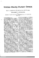
Be it known that I, IsAAc D. J oENsoN, of Kennetts Square, in the county oi' Chester and State of Pennsylvania, have invented a new and Improved Mode of Raising Oarriages, Wagons, Snc.; and I do hereby declarethat the following is a full and exact description thereof, reference being had to the accompanying drawing, which makes part of this speciiication, and in which- Figure 1 represents a side elevation of a machine embodying my invention. Fig. 2 represents a vertical section of the same, showing the internal arrangement and mode of operation. Fig. 3 represents a side view of a bracket belonging to the machine.
The nature and object of my invention consist in a novel device for raising carriages, and all vehicles, when it is necessary to remove the wheels in the process of oiling, Src.; and
To enable others skilled in the art to make and use my improvement, I will proceed to describe its construction and operation.
The drawing represents a narrow box-frame, A, open in front, except a short distance from the top, which is made closed to stiiien the frame and keep the supporting-bar G in position. B is a base for the frame A to stand D D D D D represent niches with concave bearings formed in the sides of the frame A, by which the fulcrum F can be raised or lowered to suit wagons of diierent heights. E E E E E represent horizontal bars placed across the inside of the frame A, one above another, like the rounds in a ladder, the purpose of which is to stiiien the frame, and form catches for the hook H to gripe upon.
F represents an adjustable fulcrum, the upper end being constructed like an open mortise, so as to form a hinge-like joint when connected with the short arm K of the lever I. Near the lower end it is provided with a trunnion-pin, G, which is rigidly fixed in the shaft of the fulcrum F. The pin is made round, so as to fit in the bearings D D D D D, which are made to correspond. H is a hook formed on the lower end of the shaft of the fulcrum F, and so arranged that when the upper end of the fulcrum F is drawn from within the frame A, (by elevating the lever I, as shown in Fig. 1,) it catches under the horizontal bars E E E E E, and keeps the trunnion-pin G securely in the bearings D D D D D; but when the lever I is depressed, as shown in Fig. 2, and the upper end of lthe fulcrum F carried within the frame A, the hook H is detached, and the fulcrum F can be raised or lowered at pleasure.
I represents a lever with two short arms, J and K, standing at nearly right angles to the handle L. These arms are rounded at the ends, and form tenons that correspond with mortises made in the end of the fulcrum F and supporting-bar O, with which they are connected.
C is a supporting-bar made to operate in the frame A. On the upper end is a cross-head, M, to receive the carriage-axle or weight to be lifted. At the lower end is an open mortise to receive the short arm J of the lever I,and form a hinge-like joint. Just above this joint is another mortise, in which the tenon P on the bracket O is inserted.
N is a slot formed in the back of the frame A for the bracket O to glide in when the supporting-bar C is being raised or lowered. O is a bracket placed at the back of the frame A. It is constructed with an elongated tenon, P, at one end, which is made to pass loosely through the slot N, and rigidly fastened in the supporting-bar C. By this contrivance the lower end of the supporting-bar Gis kept strictly in line within the frame A when the machine is being operated, and I am enabled to place the bracket under very low wagons and lift them without difliculty.
B. represents a pin-hole passing through the sides ofthe frame A and a short distance from the top, the object of which is to enable me to secure a connection between the lower end of the supporting-bar C and the short arinJ of the lever I. This is accomplished by first placing the supporting-bar C within the frame A and bringing the hole in the center of the joint directly inline with the pin-hole R; then insert the short arm J of the lever in the mortise, and drop in a pin that will just reach through the joint, press down the supporting-bar in the frame, and it will be secure.
S is a circular stop rigidly xed to the crosshead M, which prevents the lever I from rising beyond a certain height, and also serves as a hold by which to lift the machine.
I now construct the parts by uniting the upper end of the f'ulcrum F with the short arm K of the lever, and secure it with a rivet. I
. then place the supporting-bar C in the frame A, adjust the bracket O in the slot N, and secure it firmly to the supportingbar C by the tenon P. The short arm J of the lever is then connected with the lower end of the supporting-bar C, as heretofore described, and it is finished.
If, now, (the machine being in its normal position, Fig. 1.) the lever I be depressed, the supporting-bar C will rise, and the upper end of the fulcrum F carried forward and under the ends ofthe short arms J and K of the lever I, where it will remain steadfast until the lever be reversed.
I am aware that the trunnion-pin above described is somewhat like that shown in the patent of I. D. Johnson, December l2, 1871; but it differs in this, that the pin is made round and fits in bearings formed in the sides of the frame to correspond, and is held in place by a hook underneath, whereas the pin in the patent referred to is not round, but has a projection on one side intended to catch in niches cut in the sides of the frame to hold, it in place.
What I claim as-my invention is- 1. The adjustable fulcrum F, provided with the round trunnion-pin G and hook H, in combination with the cross-bars E E and frame A, having the niches D D, substantially as and for the purpose described.
2. The frame A. having the pin-hole R near its top to allow the connection to be made between the lower end of the supporting-bar C and the short arm of the lever I by means of the pin T, substantially as described.
3. In combination with the frame A, having the slot N, the supporting-bar, and the bracket 0, provided with the guide-faces X, which slide on the frame A and keep the supporting-bar U strictly in line with the frame A.
In testimony whereof I have hereunto subscribed my name.
ISAAC D. JOHNSON. M. D.
Witnesses:
E. T. SWAYNE, J. P. HANNUM.
Publications (1)
| Publication Number | Publication Date |
|---|---|
| US190718A true US190718A (en) | 1877-05-15 |
Family
ID=2260125
Family Applications (1)
| Application Number | Title | Priority Date | Filing Date |
|---|---|---|---|
| US190718D Expired - Lifetime US190718A (en) | Improvement in lifting-jacks |
Country Status (1)
| Country | Link |
|---|---|
| US (1) | US190718A (en) |
Cited By (1)
| Publication number | Priority date | Publication date | Assignee | Title |
|---|---|---|---|---|
| US7611160B1 (en) * | 2006-06-09 | 2009-11-03 | Ignacio Roy M | Retractable single-motion lever jack |
-
0
- US US190718D patent/US190718A/en not_active Expired - Lifetime
Cited By (1)
| Publication number | Priority date | Publication date | Assignee | Title |
|---|---|---|---|---|
| US7611160B1 (en) * | 2006-06-09 | 2009-11-03 | Ignacio Roy M | Retractable single-motion lever jack |
Similar Documents
| Publication | Publication Date | Title |
|---|---|---|
| US130449A (en) | Improvement in lifting-jacks | |
| US348480A (en) | Lifting-jack | |
| US408568A (en) | Stove-truck | |
| US116232A (en) | Improvement in lifting-jacks | |
| US121721A (en) | Improvement in lifting-jacks | |
| US255820A (en) | Carriage-jack | |
| US750287A (en) | Lifting-jack | |
| US363038A (en) | Wagon-jack | |
| US500689A (en) | Lifting-jack | |
| US189468A (en) | Improvement in lifting-jacks | |
| US404223A (en) | Wagon-jack | |
| US349698A (en) | Lifting-jack | |
| US257281A (en) | Adam boens | |
| US212806A (en) | Improvement in wagon-jacks | |
| US666642A (en) | Lifting-jack. | |
| US111942A (en) | Improvement in lifting-jacks | |
| US349179A (en) | Vehicle-jack | |
| US134086A (en) | Improvement in lifting-jacks | |
| US510230A (en) | Lifting-jack | |
| US238792A (en) | Wagon-jack | |
| US614777A (en) | Stoddard | |
| US209635A (en) | Improvement in lifting-jacks | |
| US138078A (en) | Improvement in lifting-jacks | |
| US957308A (en) | Wagon-jack. | |
| US382807A (en) | Eozell haeeis |