US1906363A - Can lid stamping mechanism - Google Patents
Can lid stamping mechanism Download PDFInfo
- Publication number
- US1906363A US1906363A US556059A US55605931A US1906363A US 1906363 A US1906363 A US 1906363A US 556059 A US556059 A US 556059A US 55605931 A US55605931 A US 55605931A US 1906363 A US1906363 A US 1906363A
- Authority
- US
- United States
- Prior art keywords
- lid
- dies
- guideway
- marking
- members
- Prior art date
- Legal status (The legal status is an assumption and is not a legal conclusion. Google has not performed a legal analysis and makes no representation as to the accuracy of the status listed.)
- Expired - Lifetime
Links
- 230000007246 mechanism Effects 0.000 title description 10
- 230000001360 synchronised effect Effects 0.000 description 5
- 101150091111 ACAN gene Proteins 0.000 description 1
- 230000000712 assembly Effects 0.000 description 1
- 238000000429 assembly Methods 0.000 description 1
- 238000010276 construction Methods 0.000 description 1
- 230000000694 effects Effects 0.000 description 1
- 238000004049 embossing Methods 0.000 description 1
Images
Classifications
-
- B—PERFORMING OPERATIONS; TRANSPORTING
- B41—PRINTING; LINING MACHINES; TYPEWRITERS; STAMPS
- B41F—PRINTING MACHINES OR PRESSES
- B41F17/00—Printing apparatus or machines of special types or for particular purposes, not otherwise provided for
- B41F17/08—Printing apparatus or machines of special types or for particular purposes, not otherwise provided for for printing on filamentary or elongated articles, or on articles with cylindrical surfaces
- B41F17/14—Printing apparatus or machines of special types or for particular purposes, not otherwise provided for for printing on filamentary or elongated articles, or on articles with cylindrical surfaces on articles of finite length
- B41F17/16—Printing apparatus or machines of special types or for particular purposes, not otherwise provided for for printing on filamentary or elongated articles, or on articles with cylindrical surfaces on articles of finite length on end or bottom surfaces thereof
Definitions
- This invention relates to can machinery and particularly to means for marking or embossing the lids of the cans for any puroses.
- An object of the invention is to provide for positively advancing can lids or ends to and through the marking dies and for so arranging the operation of the cooperating dies and lid feeding means that the lid feeding means may pass between the marking dies during periods before and after the marking operation.
- Another object is to provide rotating dies which are synchronized with the associated mechanism to permit of continuous operation of the marking means or dies.
- Another object is to provide means of the class described which are simple and eflicient in construction and operation. 1 r
- FIG. 1 is a plan view of a can feeding and lid feeding assembly normally associated with the means for attaching the lids to the cans.
- Fig. 2 is a view taken on the line 22 of Fig.1.
- Fig. 3 is a cross-sectional View taken on the line 33 of Fig.
- the can feeding assembly comprises a rotatable disc 6 overhanging a second rotatable disc 7 which in turn overhangsa circular table member 8.
- the discs 6and 7 are rotatable in the direction indicated by'the small arrows for the purpose of carrying cans toward the table member 8. This purpose is further achieved by the use of a can spacing means 9 positioned above the disc 7 and by a plate 10 positioned above the table member 8 and having aguide strip 11 attached thereto and extending above the discs 6 and'7.
- a suitable rotary conveyor 12 is positioned upon the table member 8 and serves to carry the filled cans along the surface of said table member between the edge of the plate member 10 and a suitable guide strip 18.
- a star wheel 14 comprising suitable semi-cylindrical can receiving members 15 receives the cans as delivered by the conveyor 12 and moves'the cans over to the lid feeding assembly to be described.
- the means just set forth may be any of several well known mechanisms used for such purpose, and need not] be further detailed. i
- the lid feeding assembly comprises a table portion 16 having an enlarged transversely extending aperture 17 provided intermediatelythereof and opening upon the inner edge '18 of the table member 16 adjacent the point at which the cans are delivered to the lid feeding mechanism.
- the aperture 17 has associated therewith means for providing a guideway'through which can lids are fed in synchronism with the delivery of the cans.
- This guideway begins beneath the lid stacking rack 19 and the'lid aperture 20 and comprises an arcuate' strip member '21 positioned atone side of the aperture 17 and a similarly curved ledge portion 22 formed uponthe bottom face of the table member 16 and adapted to support the edge of the lid, at one side, while the strip member 21 supports the lid at the other side.
- a swivel arm 23 is pivotally mounted upon the under face of the table 16 behind the lid aperture 20.
- the arm 23 is provided at its ends with lid sup-' porting members 24 adapted to cooperate with and support the lid and to effect move-' ment of the lid through the guideway as the arm 23 is rotated upon its pivotal mounting.
- the lid holding members 24 are adapted to move through the aperture 17 of the lid guideway.
- the members 24 are broughtinto abutment with the rear edge of each lid as its passes downwardly through the lidaperture 20, thereafter pushing the lid before it through the guideway.
- a supplementary plate which projects in the direction of the guideway as indicated at 26.
- the under face of plate 25 is provided with a lid supporting ledge 27 which forms a continuation of the ledge As the lid moves from the guideway it is received by the ledge 27 along one side while the rear portion of the lid is supported by one of the members 21.
- the marking means of the present invention are provided adjacent and in connection with the lid guideway heretofore described. These means comprise a pair of elongated die holders 29 and 30 positioned intermediatelyof and in alignment with the guideway aperture 17.
- the holder 29 is positioned above the plane of the lids moving through the. guideway and the holder 30, is in substantially the same relative position below the plane of the lids.
- Members 29 and 30 are; each rotatably mounted on central transverse axes by means of shafts 31 and 32 which are journaled in the gear casings 33and 31 attached to. the upper and under face respectively, of a table member 16.
- the inner ends of shafts 31 and 32 may be provided with worms and are designed to be driven by gears 35 and 36 fixed upon the vertical drive shaft 37.
- the die holders 29;and 30 are adapted to receive the dies 38 which may be suitably and removably attached within said holders.
- Thedetails of the die holding means form subject matter of a separate application for patent and areclaimed therein;
- suitable F means may be provided for elfecting release or non-release of a lid depending on whether or not acan is received by one of the members 15 of the star wheel 1 1.
- Said means comprises a trip arm 40 positioned above the circular conveyor 12 and adapted to be actuated through contact with each can. as the latter is received by one of the members 15.
- the trip arm 10 is fixed upon a shaft 41 (Fig. 2) said shaft at its lower end being provided with an arm .12 adapted to cooperate with a cam43 carried at the lower end of the shafted. 'The latter at its upper end
- the mechanical details o1 cooperating parts just described may likewise be effected in any desirable manner, and the particular mechanism employed may be varied as. desired.
- the trip arm 40 may be operated by can bodies for-operating a can lid feed mechanism for releasing a canlid to the action of arm 23 that may rotate con.- tinuously, or the trip arm may control intermittent rotation of the arm 23, or any other suitable cooperating mechanism, of which there are numerous disclosures in patents in this art.
- the means of this invention incorporates the step of can marking into the uninterrupted movement of the various mechanical assemblies forming a can feeding and heading structure.
- the device is simple and eflicient in operation. It is intended that the dies 38,may be quickly removed and substituted by other dies containing diiferent identification marks or numbers, and the disclosed mechanism permits such changes.
Landscapes
- Closing Of Containers (AREA)
Description
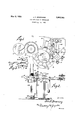
May 2, 1933. J. K. BROWNING CAN LID STAMPING MECHANISM Filed Aug. 10, 1931 Patented May 2, 1933 UNITED "STATES PAT N Q .ToHN K. BROWNING, or CINCINNATI, onio, AssIeNoR TO THE HEEKIN GAN'COMPANY;
or CINCINNATI, 0310,14 CORPORATION or onro oAN LID STAMPING MEcnAN-isir Application filed August 10, 1931i Serial No. 556,059.
This invention relates to can machinery and particularly to means for marking or embossing the lids of the cans for any puroses.
' An object of the invention is to provide for positively advancing can lids or ends to and through the marking dies and for so arranging the operation of the cooperating dies and lid feeding means that the lid feeding means may pass between the marking dies during periods before and after the marking operation.
Another object is to provide rotating dies which are synchronized with the associated mechanism to permit of continuous operation of the marking means or dies.
Another object is to provide means of the class described which are simple and eflicient in construction and operation. 1 r
These and other objects are attained by the means described herein and set forth in the accompanying drawing, in'which:
'Fig. 1 is a plan view of a can feeding and lid feeding assembly normally associated with the means for attaching the lids to the cans. i Fig. 2 is a view taken on the line 22 of Fig.1.
Fig. 3 is a cross-sectional View taken on the line 33 of Fig. With reference to the drawing: The can feeding assembly comprises a rotatable disc 6 overhanging a second rotatable disc 7 which in turn overhangsa circular table member 8. The discs 6and 7 are rotatable in the direction indicated by'the small arrows for the purpose of carrying cans toward the table member 8. This purpose is further achieved by the use of a can spacing means 9 positioned above the disc 7 and by a plate 10 positioned above the table member 8 and having aguide strip 11 attached thereto and extending above the discs 6 and'7. A suitable rotary conveyor 12 is positioned upon the table member 8 and serves to carry the filled cans along the surface of said table member between the edge of the plate member 10 and a suitable guide strip 18. A star wheel 14 comprising suitable semi-cylindrical can receiving members 15 receives the cans as delivered by the conveyor 12 and moves'the cans over to the lid feeding assembly to be described. The means just set forth may be any of several well known mechanisms used for such purpose, and need not] be further detailed. i
' The lid feeding assembly comprises a table portion 16 having an enlarged transversely extending aperture 17 provided intermediatelythereof and opening upon the inner edge '18 of the table member 16 adjacent the point at which the cans are delivered to the lid feeding mechanism. The aperture 17 has associated therewith means for providing a guideway'through which can lids are fed in synchronism with the delivery of the cans.
This guideway begins beneath the lid stacking rack 19 and the'lid aperture 20 and comprises an arcuate' strip member '21 positioned atone side of the aperture 17 and a similarly curved ledge portion 22 formed uponthe bottom face of the table member 16 and adapted to support the edge of the lid, at one side, while the strip member 21 supports the lid at the other side. A swivel arm 23. is pivotally mounted upon the under face of the table 16 behind the lid aperture 20. The arm 23 is provided at its ends with lid sup-' porting members 24 adapted to cooperate with and support the lid and to effect move-' ment of the lid through the guideway as the arm 23 is rotated upon its pivotal mounting. It will be observed by reference'to Fig. 1 that the lid holding members 24 are adapted to move through the aperture 17 of the lid guideway. In operation the members 24 are broughtinto abutment with the rear edge of each lid as its passes downwardly through the lidaperture 20, thereafter pushing the lid before it through the guideway. At the inner side of the table 16 is provided a supplementary plate which projects in the direction of the guideway as indicated at 26. The under face of plate 25 is provided with a lid supporting ledge 27 which forms a continuation of the ledge As the lid moves from the guideway it is received by the ledge 27 along one side while the rear portion of the lid is supported by one of the members 21. At this point the star wheel 14 in its operation, is in a position to receive one side of the lid upon the arcuate ledge 28 provided in each of the semi-cylindrical can receiving members 15. Said members 15 thereafter carry the lid over to the can heading mechanism (not shown), the lid being moved along the supporting ledge 27 The guideway means just described are likewise known in the art and need no further. detailing. i
The marking means of the present invention are provided adjacent and in connection with the lid guideway heretofore described. These means comprise a pair of elongated die holders 29 and 30 positioned intermediatelyof and in alignment with the guideway aperture 17. The holder 29 is positioned above the plane of the lids moving through the. guideway and the holder 30, is in substantially the same relative position below the plane of the lids. Members 29 and 30 are; each rotatably mounted on central transverse axes by means of shafts 31 and 32 which are journaled in the gear casings 33and 31 attached to. the upper and under face respectively, of a table member 16. The inner ends of shafts 31 and 32 may be provided with worms and are designed to be driven by gears 35 and 36 fixed upon the vertical drive shaft 37. The die holders 29;and 30 are adapted to receive the dies 38 which may be suitably and removably attached within said holders. Thedetails of the die holding means form subject matter of a separate application for patent and areclaimed therein;
t will be seen by reference to Fig. 3 that the marking dies 38 project outwardly of the die holders. Said holders are so positioned relative to one another, that when they are rotated to endwise alignmentas indicated,
indottedlines in Fig. 3, they are adapted to mark a lid 39 passed between the dies, The die holders are adapted to becontinuously rotated and the movement thereof is so synchronized with the action of the lid movarm 23 that the endwise alignment of the dies. occurs at that moment when the lid iscentrally disposed between the dies. v It will be understood that said endwise alignment is but a momentary relationship and that the dies immediately return toward the horizontal whereby ample space is provided for movementof the lid. holding members 2 1 and the, outer portions of arm 23 between the dies. In this way a continuous and smooth flow of mechanical motion may be attained which is particularly desirable not only for etficiencyin operation but likewise for attaining the maximum of speed.
As indicated in Figs. 1 and 2, suitable F means may be provided for elfecting release or non-release of a lid depending on whether or not acan is received by one of the members 15 of the star wheel 1 1. Said means comprises a trip arm 40 positioned above the circular conveyor 12 and adapted to be actuated through contact with each can. as the latter is received by one of the members 15. The trip arm 10 is fixed upon a shaft 41 (Fig. 2) said shaft at its lower end being provided with an arm .12 adapted to cooperate with a cam43 carried at the lower end of the shafted. 'The latter at its upper end The mechanical details o1 cooperating parts just described may likewise be effected in any desirable manner, and the particular mechanism employed may be varied as. desired. For example, the trip arm 40 may be operated by can bodies for-operating a can lid feed mechanism for releasing a canlid to the action of arm 23 that may rotate con.- tinuously, or the trip arm may control intermittent rotation of the arm 23, or any other suitable cooperating mechanism, of which there are numerous disclosures in patents in this art.
As suggested above, the means of this invention incorporates the step of can marking into the uninterrupted movement of the various mechanical assemblies forming a can feeding and heading structure. The device is simple and eflicient in operation. It is intended that the dies 38,may be quickly removed and substituted by other dies containing diiferent identification marks or numbers, and the disclosed mechanism permits such changes.
' .It willbe understood, that the synchronism of the lid moving means with the lid stamping means or dies may be attained by any suitable means or gearing which herein is merely indicated by the driving gears 45 andlG. a
\Vhat is claimed is: v
1. Thecombination with a horizontal can lid guideway adapted to contact lateral portions only of the lids and: means movable in the guide-way for eliecting passage of the lids.
tioned in the guideway, said dies being adapt.-v
ed when in endwise alignment tomark a lid passing therebetween, and means for continuously rotating the dies, such rotation being synchronized with the lid moving means whereby the dies are actuated into endwise alignment upon each passage of a lid therebetween and are then moved out of such alignment at which time the lid-moving means pass between the dies.
2. The combination with a horizontal can lid guideway and means for effecting passage of lids therethrough, of a pair of vertically aligned marking members rotatably mounted one above and one below the guideway and adapted to mark'lids successively passed therebetween, and means for continuously rotating the marking members in synchronism with the lid moving means, portions of said marking members during rotation being adapted for successive approach and withdrawal relative to one another the marking members marking the lids during said approach relationship.
3. The combination with a horizontal can lid guideway and means movable through the guideway for effecting passage of lids therethrough, of a pair of vertically aligned marking members rotatably mounted one above and one below the guideway, said members being provided with extended portions adapted to mark a lid passed therebetween during rotation of said members, and with restricted portions, the lid moving means passing between said restricted portions during rotation of the marking members, and means for continuously rotating marking members and synchronized with the lid moving means for effecting the indicated operative relationships.
4. The combination of guideway forming means for slidably supporting blanks movable through the guideway, a pair of rotating dies each having a marking face and a clearance face, the marking faces of the pair of dies cooperating for simultaneous contact with opposite sides of a blank passing hrough the guideway, the marking faces being spaced farther from their respective centers of rotation than are the clearance faces spaced from said centers of rotation, means for rotating the dies and for successively attaining apposition of the marking faces and apposition of the clearance faces of the dies, and blank moving means synchronized with the dies for moving blanks between the dies and for passing between the clearance faces of the dies when the clearance faces are in apposition.
5. The combination of guideway forming means for slidably supporting blanks movable through the guideway, a pair of rotating dies, together having cooperating marking faces for movement into apposition for com tacting opposite sides of a blank passing through the guideway, said dies also having cooperating clearance faces for movement into apposition for providing a recurring passageway between the dies, means for rotating the dies for attaining successive apposition of the marking faces and of the clearance faces, and means for moving blanks through the way and between the marking faces when in apposition, said means passing through the recurring passageway between the dies incident to apposition of the clearance faces.
In testimony whereof, I have hereunto subscribed my name this 29th day of July, 1931.
JOHN K. BROWNING.
Priority Applications (1)
| Application Number | Priority Date | Filing Date | Title |
|---|---|---|---|
| US556059A US1906363A (en) | 1931-08-10 | 1931-08-10 | Can lid stamping mechanism |
Applications Claiming Priority (1)
| Application Number | Priority Date | Filing Date | Title |
|---|---|---|---|
| US556059A US1906363A (en) | 1931-08-10 | 1931-08-10 | Can lid stamping mechanism |
Publications (1)
| Publication Number | Publication Date |
|---|---|
| US1906363A true US1906363A (en) | 1933-05-02 |
Family
ID=24219735
Family Applications (1)
| Application Number | Title | Priority Date | Filing Date |
|---|---|---|---|
| US556059A Expired - Lifetime US1906363A (en) | 1931-08-10 | 1931-08-10 | Can lid stamping mechanism |
Country Status (1)
| Country | Link |
|---|---|
| US (1) | US1906363A (en) |
Cited By (3)
| Publication number | Priority date | Publication date | Assignee | Title |
|---|---|---|---|---|
| US2435215A (en) * | 1944-12-29 | 1948-02-03 | Herbert P Hintz | Reciprocating work carrier for marking machines |
| US2551633A (en) * | 1946-06-26 | 1951-05-08 | American Can Co | Changeable marking mechanism |
| US2601922A (en) * | 1945-08-20 | 1952-07-01 | Shellmar Products Corp | Device for separating cartons of eggs |
-
1931
- 1931-08-10 US US556059A patent/US1906363A/en not_active Expired - Lifetime
Cited By (3)
| Publication number | Priority date | Publication date | Assignee | Title |
|---|---|---|---|---|
| US2435215A (en) * | 1944-12-29 | 1948-02-03 | Herbert P Hintz | Reciprocating work carrier for marking machines |
| US2601922A (en) * | 1945-08-20 | 1952-07-01 | Shellmar Products Corp | Device for separating cartons of eggs |
| US2551633A (en) * | 1946-06-26 | 1951-05-08 | American Can Co | Changeable marking mechanism |
Similar Documents
| Publication | Publication Date | Title |
|---|---|---|
| US3204756A (en) | Apparatus for the intermittent transport of workpieces, especially for the feeding of wrappers, labels, or the like in wrapping machines | |
| NO173858B (en) | MACHINE FOR APPLYING AN EXTENSIVE MATERIAL STRAP ON A WALKING SUBSTRATE | |
| US1906363A (en) | Can lid stamping mechanism | |
| US3556909A (en) | Apparatus for label cutting and application | |
| US4072117A (en) | Canister indexing spout-inserting machine | |
| US2761545A (en) | Conveying means for a marking apparatus | |
| US3200027A (en) | Apparatus for applying body and neck labels to bottles | |
| US1025926A (en) | Combined printing and addressing machine. | |
| US2175177A (en) | Article feeder for can making machines | |
| DE965384C (en) | Labeling machine for upright objects | |
| US4833864A (en) | Method and apparatus for closing containers | |
| US2406151A (en) | Can end marking means | |
| US1880662A (en) | Printing and cap forming machine | |
| US1972858A (en) | Friction plug inserting apparatus | |
| US2096346A (en) | Bottle cap-making and applying machine | |
| US2358026A (en) | Spot forming means for crown cap spotting machines | |
| US1719230A (en) | Thread-rolling machine | |
| US2436821A (en) | Feeding and gauging mechanism | |
| US1436761A (en) | Machine for positioning and clinching ends upon can bodies | |
| US2277597A (en) | Machine for printing on cylindrical glassware | |
| US2330235A (en) | Notching mechanism | |
| US1178357A (en) | Automatic flanging-machine. | |
| US429872A (en) | Can forming and soldering machine | |
| US1818557A (en) | Cover lining apparatus | |
| US3448601A (en) | Rotary forging apparatus |