US1900722A - Method of and machine for forming metal plates - Google Patents
Method of and machine for forming metal plates Download PDFInfo
- Publication number
- US1900722A US1900722A US576054A US57605431A US1900722A US 1900722 A US1900722 A US 1900722A US 576054 A US576054 A US 576054A US 57605431 A US57605431 A US 57605431A US 1900722 A US1900722 A US 1900722A
- Authority
- US
- United States
- Prior art keywords
- plate
- shaft
- channels
- rolls
- lever
- Prior art date
- Legal status (The legal status is an assumption and is not a legal conclusion. Google has not performed a legal analysis and makes no representation as to the accuracy of the status listed.)
- Expired - Lifetime
Links
Images


Classifications
-
- B—PERFORMING OPERATIONS; TRANSPORTING
- B21—MECHANICAL METAL-WORKING WITHOUT ESSENTIALLY REMOVING MATERIAL; PUNCHING METAL
- B21D—WORKING OR PROCESSING OF SHEET METAL OR METAL TUBES, RODS OR PROFILES WITHOUT ESSENTIALLY REMOVING MATERIAL; PUNCHING METAL
- B21D13/00—Corrugating sheet metal, rods or profiles; Bending sheet metal, rods or profiles into wave form
- B21D13/04—Corrugating sheet metal, rods or profiles; Bending sheet metal, rods or profiles into wave form by rolling
- B21D13/045—Corrugating sheet metal, rods or profiles; Bending sheet metal, rods or profiles into wave form by rolling the corrugations being parallel to the feeding movement
Definitions
- This invention relates to a method of forming metal plates, and has reference more particularly to a method of forming continuous and noncontinuous ribs in a metal sheet.
- the invention also relates to a machine suitable for carrying out the above described method.
- This roof deck is composed of a metal sheet in which is formed a plural- ,ity of continuous, longitudinal grooves or channels and between the continuous channels are located non-continuous channels or grooves so arranged as to permit overlapping of the-roof deck plates as they are supported upon the framework of the roof. It is desirable to form the roof deck plates continuously and to accomplish the method with the machine disclosed in such a way that the non-continuous channels are formed vat about the same time that the continuous channels are formed.
- An object of this invention is to provide a method of forming continuous and non-continuous grooves or channels in a metal sheet.
- Another object of the invention is to pro.- vide an apparatus for accomplishing the method, in which the movement of the form- 50 ing rolls for the non-continuous channels Serial No. 576,054.
- Fig. 4 is a side elevation of the delivery end of the machine with parts broken away to disclose the construction
- Fig. 5 is a transverse sectional view through the machine taken on line 5-5 of Fig. 4,
- Fig. 6 is a sectional elevation through the machine taken on line 6-6 of Fig. 4, and
- Fig. 7 is an elevation of a portion of the mechanism looking in the direction of line 77 of Fig. 5. 76
- our improved roof deck comprises a metal plate 10, which is preferably composed of steel but may be of any other suitable metal.
- a plurality of channels 11 are formed in said plate in spaced parallel relation, said channels being preferably few in number and spaced com paratively far apart so as to provide a deck plate surface 12 in which the distance between channels is great compared to thewidth of the channels.
- the centers of the channels 11 are preferably equi-distant the entire length of the plate 10.
- These channels have upwardly extending legs 13 which are substantially parallel adjacent oneend of the deck plate 12, said legs flaring only slightly outwardly to permit satisfactory rolling during the fabrication of said plate.
- the ribs or channels 14 are rolled in substantially the center of each of the plate surfaces 12, said ribs extending from one extreme end of the plate to a point materially short of 100 the opposite end of the plate 10.
- the rib 14 serves the purposes of drawing together the le s 13 of adjacent channels so that said legs are upwardly at a substantial angle to the vertical, thus permitting the parallel legs of the adjoining plate to telescope slightly into the flared legs of a deck plate with the overlapping deck plate surfaces 12 in face to face abutting relation.
- the ribs 14 also serve to give longitudinal stiffness and strength to the entire deck plate construction. By actual test, we have found that these ribs 14 make the deck plate in excess of 10% stronger than it is without the formation of said ribs 14.
- One edge of the deck plate 10 is provided with a downwardly extending flange 15, and the opposite edge of said plate is provided with a downwardly extending L-shaped channel 16.
- the flange 15 of one deck plate is adapted to engage in or interlock with the L-shaped channel 16 of the adjoining deck plate.
- Suitable clips are provided for attaching the deck plates to the supporting framework or purlins, as has been more fully described in said copending application.
- the sheets of metal to be corrugated or.
- a pair of rolls 33 and 34 is provided, the latter being movable substantially vertically so as to move into and out of engagement with the moving metal plate.
- the roll 33 is rovided with annular grooves 35, and the r0 1 34 is provided with annular shoulders 36 for engaging in the grooves 35.
- the en agement of the shoulders 36 with the dec plate forces said plate downwardly into the grooves 35 to form the channels 14.
- Annular shoulders 37 formed on roll 34 engage the channels 11 previously formed in the plate 12, so as to accurately position the plate 12 relative to the shoulders 36.
- the roll 33 is provided with annular grooves 38, which register with the annular flanges 37.
- the roll 33 is keyed onto a shaft 39 and the roll 34 onto a shaft 40.
- Each of the shafts 39 and 40 is provided with an annular shoulder 41 and a spacing collar 42 extending between said shoulder 41 and each of the rolls.
- Lock-nuts 43 are provided on each of the shafts 39 and 40 to rigidly position the rolls 33 and 34 on their shafts with the forming shoulders and grooves in accurate registry position.
- the shaft 39 is rotatably and rigidly supported in stationary bearings 44, 45 and 46, which are preferably of the ball-bearing type and are mounted in suitable cast framework 47 which serves to support the moving parts of the machine.
- a bevel gear 48 is provided on the end of shaft 39 and engages with a bevel gear 49 on the longitudinal shaft 26 so as to accomplish the continuous rotation of shaft 39 and roll 33 at the exact speed of the deck plate.
- one end of said shaft 40 is rotatably mounted in vertically movable bearings 50 and 51, each of which is supported by a bifurcated bell-crank lever between the arms of which is positioned a spur gear 53 which is rigidly secured to the shaft 40.
- Two arms 54 of the lever 52 extend rearwardly of the machine and are pivotally mounted upon a shaft 55 by means of bearings 56, one being provided for each of said arms 54.
- the ends of shaft 55 are rigidly mounted in the walls of the machine housing 57, and a spur gear 58 is secured to said shaft between the lever arms 54.
- the gear 58 meshes with the gear 53 and also meshes with an idler spur gear 59, which in turn meshes with a spur gear 60 which is rigidly secured on the shaft 39.
- the end of the shaft 40 opposite the bearings 50 and 51 is rotatably mounted in a bearing 62 which is formed intermediate the ends of a bell-crank lever 63.
- One end of the lever 63 is pivot-ally mounted by means of pin 64 to a rigid bracket 65. the latter also serving to support the bearing 46 for shaft 39.
- a cam shaft 67 is rotatably mounted in bearings 68 which are formed on bearin brackets 69, the latter being secured by bolts 70 to the framework of the machine.
- a bearing bracket 71 also serves to support the outer end of shaft 67.
- lever 76 and the roller 75 is mounted upon the outer end of a similar of pin 81 to the free end of lever 52.
- lever 87 on the opposite side of the machine.
- the end of the lever 76 opposite the roller 74 is pivotally secured by means of pin 77 to a bracket 78.
- a rod 79 is pivotally connected by means of pin 80 to the lever 76 intermediate its ends, and the upper end of the rod 79 is pivotally secured by mealns T 10' rod 79 passes loosely upwardly through a bottom 82 formed on the housing 57, and a spring 83 is mounted on the rod 79 between a .nut 84 on said rod and the bottom '82, so as to urge the rod 79- and lever 76 upwardly to maintain the roller 74 in contact with the cam 72.
- a similar rod 85 is positioned on the opposite side of the machine, being pivotally connected at its upper end to the lever 63 by means of pin 86. The lower end of rod 85 is pivotally connected to a lever 87'similar to lever 76.
- bracket 78 With a face in sliding contact with a slide way 89 formed on a bracket 90.
- a screw 91 is rotatably mounted in a vertical position in the bracket 90, and shoulder 92 formed on the bracket 78 is threaded to receive the screw 91.
- the upper end of the screw 91 is provided with a worm wheel 93 which meshes with a worm 94 secured to a shaft 95, the latter being provided with a hand-wheel 96 for manually adjusting the vertical position of the pin
- the shaft 67 is caused to rotate intermittently for a single revolution, so as to cause the non-continuous channels 14 to be formed in the deck plate. For rotating the shaft 67,
- a spur gear 98 is secured to the outer end. of a shaft 99 which is rotatably mounted in bearings 100, 101 and 102 secured to the framework of the machine.
- a bevel gear 103 is secured to the shaft 99 and meshes with a bevel gear 104a on the forward end of longitudinalshaft 26;
- An idler spur gear 104 is rotatably mounted upon a stub shaft 105, secured to the framework of the machine.
- the gear 104 meshes with a spur gear 106, which in turn is secured to a sleeve 107 mounted for rotary movement on the shaft 67.
- a clutch disc, 109 is operated by toggle arms 110 from a collar 1'11. Ears 112 are secured to the collar 111 and a ring 113 embraces the collar 111, having outstanding integral pins 114 for receiving the ends of push rods 115.
- a collar 116 is rigidly secured to the shaft 67, and a compression spring 117 is mounted upon the shaft 67' between the collar 116 and a collar 118. Outstanding ears 119 are formed on the collar 118 for receiving the endsof rods 115, said rods being threaded to ,,receive lockin nuts 120.
- the clutch disc 109 and the co lars 111 and 118 are secured to the shaft 67 by means of feather keys so as to have free sliding movement on said shaft.
- the spring 117 normally tends to hold the clutch disc 109 out of engagement with the clutch drum 108 so that shaft 67 does not rotate.
- a bell-crank lever is pivoted on a pin 121, said pin being secured to a bracket 122.
- One arm 123 of said lever extends downwardly and engages against the annular surface of the collar 118.
- a counter-clockwise movement of the bell-crank lever, as seen inFig. 3 causes the lever arm 123 to move the collar-118 to the right, so that a shoulder 124 on said collar 118 rides up on an annular shoulder 125 formed on the bracket 122, thus causing clutch disc 109 to engage the clutch drum 108 and rotate the shaft 67 through one revolution, after which the shoulder 124 again drops into place, thereby releasing the clutch.
- a second arm 126 of the bell-crank lever is pivotally connected by a rod 127.to a spring not shown contained in a spring cylinder 128, the latter being pivotally anchored at one end to a rod 129 secured to the framework of the machine or other fixed point.
- the spring and cylinder 128 normally tend to move the lever arm 126 in a counter-clockwise direction as seen in Fig. 3, against the action of spring 117.
- a catch 130 is pivotally mounted on pin 131 securedto bracket 122, said catch normally tending to engage behind a-shoulder 132 formed on a lever 133.
- the lever 133 is pivotally mounted on a pin 134- secured to the bracket 122, and an arcuate connecting link 135 is pivotally connected to the catch 130 and the lever arm 126, said link tending to cause the catch 130 to follow the movements of lever arm 126.
- a flat spring 137 is secured at one end to the bracket 122 and presses downwardly on top of the catch arm-133 so as to securely ,hold the catch 130 in locked position.
- lever arm 126 The downward movement of lever arm 126 is also limited by a stop 147.
- the clutch is engaged and shaft 67 makes one complete revolution until the large diameter section on said cam 146 again raises the lever arm 126 so that catch 130 again engages behind catch shoulder 132 ready for a new cycle of operation.
- the solenoid is released, the armature 142 moves downwardly so that a shoulder 148 formed on the rod 143 rests upon a flat leaf spring 149 which is secured to a bracket 150.
- an ironing roll 151 is mounted securely upon the shaft 99 in the same general manner that the roll 33 is mounted upon the shaft 39.
- a co-operating ironing roll 152 is mounted upon a shaft 153 which is rotatably supported in bearings 154, 155 and 156, these bearings being arranged for vertical adjustment by means of adjusting screws 157, 158 and 159 respectively, so that the pressure of the rolls upon the metal plate can be accurately adjusted.
- the switch arm 139 is pivotally supported upon a bracket 162 by a pin 163.
- the bracket 162 has a collar 164 which is slidably mounted upon a bar 165.
- the collar 164 is provided with a catch handle 166 so that a catch 167 will engage suitable recesses in the upper surface of the bar 165, thus permitting the collar 164 to be located in any desired position along said bar 165.
- the bar 165 is slidably mounted in a pair of bearings 168 and 169.
- a bracket 170 is associated with the bearing 169 and has an outstanding flange 171 for receiving a micrometer adjusting screw 172.
- the section of the bar 165 extending beyond the bearing 169 is graduated and a pointer 173 on the bracket 170 indicates the position of the bar 165- and switch arm 139.
- the flat metal plates to be formed into shape are moved manually along the table 17 between the guides 18 until the plate is gr pped between the first pair of forming rolls 19 and 20.
- These rolls and subsequent forming rolls are caused to rotate continuously by a motor 22a operating through speed reducer 23, chain 24, shaft 26 and bevel gears 27 and 28.
- the first ten pairs of forming rolls shown in Fig. 2 serve to form the continuous channels 11 and 16 and the flange 15 in the plate.
- the plate For forming the non-continuous channels 14 in the plate, as the plate moves outwardly .from the last pair of continuous forming rolls, it passes between the non-continuous forming rolls 33 and 34 with the cams 72 and 73 in the position shown in Fig. 4 in which the large radius section of the cams press the levers 76 and 87 downwardly against the action of springs 83 so that said rolls 33 and 34 firmly grip the plate and form the non-continuous grooves or channels 14.
- the plate passes between ironing rolls 151 and 152 which serve to straighten out any irregularities existing in the plate and then the forward end of the plate engages switch arm 139.
- switch arm 139 serves to close the electric current 140 and actuates the solenoid 141 so as to raise the solenoid armature 142 and rod 143.
- the raising of shoulder 144 releases the catch lever 133 so that catch 130 is disengaged from the catch shoulder 132 and lever 126 swings downwardly under the action of a spring in spring cylinder 128 so that roller 145 engages the cam 146.
- the lever arm 123 pushes the collar 118 to the right as seen in Fig. 3, thus causing the clutch disc 109 to engage the clutch drum 108.
- the clutch drum 108 has been continuously rotated with its sleeve 107 to which is secured the spur gear 106 meshing with idler gear 104, which in turn meshes with gear 98 on the end of driven shaft 99.
- the actuation of the clutch 109 causes the shaft 67 to rotate so that the rollers 74 and engage the small radius section of the cams 72 and 73, respectively, and the forming roll 152 is moved upwardly by the action of springs 83 on the levers 52 and 63.
- the cams 72 and 73 are so shaped that the raising of levers 76 and 87 and forming roll 152 occurs gradually so that the end of the discontinuous channels 14 gradually taper off into the flat deck plate 12, leaving the end of the deck plate in a fiat condition so that overlapping of the deck plate in roof construction is possible.
- the shoulder 124 again drops into position in the recess in the bracket 125 so that the clutch is released and at the same time the large radius section of cam 146 engages the roller 145 and raises the lever 126 and catch lever 130 so that the latter engages behind the catch shoulder 132 ready for a new cycle of operation.
- the pressure of the forming rolls 19 and 20 is adjusted by means of hand-wheels 31 and the pressure between the ironing rolls 151 and 152 is adjusted by means of screws 157, 158 and 159.
- the location of the fulcrum pins 77 of levers 76 and 87, and therefore the pressure of the non-continuous roll 34 on roll 33, is adjusted by means of handwheels 96.
- the position of the switch arm 189 is regulated by actuating the catch lever 166 and moving the collar 164 along the bar 165 to the desired position.
- a micrometer adjustment of the switch arm 139 is secured by sliding the bar 165 axially through the bearings 168 and 169 by means of micrometer screw 172.
- a roof deck plate comprising the formation of a plurality of spaced parallel channels therein coextensive with the length thereof, and having substantially parallel sides, then forming ribs in said plate intermediate said channels and extending from one end of the plate but terminating short of the opposite end thereof to cause the sides of the channels in the ribbed portion of the plate to flare.
- a roof deck plate comprising the formation of a plurality of spaced parallel channels therein coextensive with the length thereof and hav ing substantially parallel sides, said channels being so spaced that the width of the plate between adjacent channels will be materially greater than the width of each channel, then forming a relatively shallow rib in said plate intermediate said channels and extending from one end of the plate but terminating short of the opposite end thereof, to cause the sides of the channels in the ribbed portion of the plate to flare.
- a pair of rolls for rollin non-continuous channels in said plates uring the continuous movement thereof, and meanscontrolled by the movement of the lates to move one of said rolls away from t e other of said rolls so as to discontinue the forming action of said rolls on said plates.
- a machine for forming metal plates means for moving said plates along a predetermined path, a pair of non-continuous forming rolls arranged to intermittently engage a plate so as to roll a non-continuous ,channel in the face thereof, a lever for moving one of said rolls relative to the other of said rolls cam means for actuating said lever, a shaft for rotating said cam, and a one-revolution clutch controlled by the movement of said plate for rotating said arranged to form a non-continuous channel in said plate, a lever for separating said rolls so that the channels in said plate extend less than the full length of said plate, and means for automatically actuating said lever at predetermined intervals.
- a machine for forming metal plates means for moving a plate along a predetermined path, a pair of forming rolls arranged to operate upon said plate so as to form a non-continuous channel in said plate, a solenoid associated with said rolls, means associated with said rolls for actuation of said solenoid at predetermined intervals depending upon the movement of said plate, and means associated with said solenoid to. separate said rolls when said solenoid is actuated.
Description
March 7, 1933.
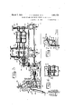
F. A. MANSKE El AL METHOD OF AND MACHINE FOR FORMING METAL PLATES Filed Nov. 19, 1931 3 Sheets-Sheet 1,
INV ENTOR S FEED 4 Minus/ 5. EUGENE NODENM/fll BYOLIVEIE E -.G/50o-.
March 7, 933- F. A. MANSKE ET AL METHOD OF AND MACHINE FOR FORMING METAL PLATES Filed Nov. l9, 1951 3 Sheets-Shee't 2 March 7, 1933. F, A, MA r AL 1,900,722
METHOD OF AND MACHINE FOR FORMING METAL PLATES Filed NOV. 1.9, 1931- 3 Sheets-Sheet 3 EUGENE oeAlmL'or OLIVE? -($Iasou.
A'r-ronus gj Patented Mar. 7, 1933 UNITED STATES PATENT OFFICE FRED A. MANSKE, EUGENE W. ODENWALDT, AND OLIVER E. GIBSON, OF CHICAGO, ILLINOIS, ASSIGNORS TO UNITED STATES GYPSUM COMPANY, OF CHICAGO, ILLINOIS,
A CORPORATION OF ILLINOIS METHOD OF AND MACIEIINE FOR FORMING METAL PLATES Application filed November 19, 1931.
This invention relates to a method of forming metal plates, and has reference more particularly to a method of forming continuous and noncontinuous ribs in a metal sheet.. The invention also relates to a machine suitable for carrying out the above described method.
This application is a continuation in part of an application by the same inventors, Serial No. 562,522, filed September 12, 1931, entitled Roof and floor construction In this copending application is disclosed a plate having longitudinal continuous and non-continuous grooves or channels for the purpose of forming a roof deck having great longitudinal strength, and a method of manufacturing this roof deck was disclosed. The present application deals more specifically with this method of manufacture of the roof deck or any type of corrugated plate, and discloses in detail a machine suitable for carrying out the method.
' While the method and machine disclosed in the present application is suitable for use on a wide variety of sheet-metal products, or products of a non-metallic nature, it is especially useful in forming the metal roof deck disclosed in the aforementioned copending application. This roof deck is composed of a metal sheet in which is formed a plural- ,ity of continuous, longitudinal grooves or channels and between the continuous channels are located non-continuous channels or grooves so arranged as to permit overlapping of the-roof deck plates as they are supported upon the framework of the roof. It is desirable to form the roof deck plates continuously and to accomplish the method with the machine disclosed in such a way that the non-continuous channels are formed vat about the same time that the continuous channels are formed.
An object of this invention, therefore, is to provide a method of forming continuous and non-continuous grooves or channels in a metal sheet.
Another object of the invention is to pro.- vide an apparatus for accomplishing the method, in which the movement of the form- 50 ing rolls for the non-continuous channels Serial No. 576,054.
-machine taken on line 3-3 of Fig. 2,
Fig. 4 is a side elevation of the delivery end of the machine with parts broken away to disclose the construction,
Fig. 5 is a transverse sectional view through the machine taken on line 5-5 of Fig. 4,
Fig. 6 is a sectional elevation through the machine taken on line 6-6 of Fig. 4, and
Fig. 7 is an elevation of a portion of the mechanism looking in the direction of line 77 of Fig. 5. 76
As disclosed in our aforementioned copending application, our improved roof deck comprises a metal plate 10, which is preferably composed of steel but may be of any other suitable metal. A plurality of channels 11 are formed in said plate in spaced parallel relation, said channels being preferably few in number and spaced com paratively far apart so as to provide a deck plate surface 12 in which the distance between channels is great compared to thewidth of the channels. The centers of the channels 11 are preferably equi-distant the entire length of the plate 10. These channels have upwardly extending legs 13 which are substantially parallel adjacent oneend of the deck plate 12, said legs flaring only slightly outwardly to permit satisfactory rolling during the fabrication of said plate.
After the channels 11 have been rolled with substantially parallel sides 13, the ribs or channels 14 are rolled in substantially the center of each of the plate surfaces 12, said ribs extending from one extreme end of the plate to a point materially short of 100 the opposite end of the plate 10. The rib 14 serves the purposes of drawing together the le s 13 of adjacent channels so that said legs are upwardly at a substantial angle to the vertical, thus permitting the parallel legs of the adjoining plate to telescope slightly into the flared legs of a deck plate with the overlapping deck plate surfaces 12 in face to face abutting relation. The ribs 14 also serve to give longitudinal stiffness and strength to the entire deck plate construction. By actual test, we have found that these ribs 14 make the deck plate in excess of 10% stronger than it is without the formation of said ribs 14.
One edge of the deck plate 10 is provided with a downwardly extending flange 15, and the opposite edge of said plate is provided with a downwardly extending L-shaped channel 16. The flange 15 of one deck plate is adapted to engage in or interlock with the L-shaped channel 16 of the adjoining deck plate. Suitable clips are provided for attaching the deck plates to the supporting framework or purlins, as has been more fully described in said copending application.
The sheets of metal to be corrugated or.
formed into roof plates or other desired articles of manufacture, are placed upon a table 17 between longitudinal guides 18, and are advanced between an upper roll 19 and a lower roll 20 of a rolling machine having side frames 21 supported on standards 22. Several pairs of these rolls similar to the rolls 19 and 20 are required as seen in Fig. 2, the pairs of rolls differing slightly in shape so as to gradually form the plate with channels 11 and 16 and the flange .15. Power for turning the rolls 19 and 20 and the following pairs of rolls is supplied from a motor 22a connected to a speed reducer 23. A chain 24 connects the speed reducer 23 to a sprocket wheel 25 secured to a shaft 26 which runs longitudinally the full length of the machine. A series of bevel gears 27 are secured to the shafts 29 which carry the rolls 20. Suitable screws 30 are provided with adjusting handwheels 31, so that the pressure between the rolls 19 and 20 can be easily adjusted to give the proper forming action on the metal sheet.
One of the salient features of our invention resides in the forming of the noncontinuous grooves or channels 14 in the deck plate 12. In order to form these grooves, a pair of rolls 33 and 34 is provided, the latter being movable substantially vertically so as to move into and out of engagement with the moving metal plate. The roll 33 is rovided with annular grooves 35, and the r0 1 34 is provided with annular shoulders 36 for engaging in the grooves 35. The en agement of the shoulders 36 with the dec plate, forces said plate downwardly into the grooves 35 to form the channels 14. Annular shoulders 37 formed on roll 34 engage the channels 11 previously formed in the plate 12, so as to accurately position the plate 12 relative to the shoulders 36. The roll 33 is provided with annular grooves 38, which register with the annular flanges 37.
The roll 33 is keyed onto a shaft 39 and the roll 34 onto a shaft 40. Each of the shafts 39 and 40 is provided with an annular shoulder 41 and a spacing collar 42 extending between said shoulder 41 and each of the rolls. Lock-nuts 43 are provided on each of the shafts 39 and 40 to rigidly position the rolls 33 and 34 on their shafts with the forming shoulders and grooves in accurate registry position. The shaft 39 is rotatably and rigidly supported in stationary bearings 44, 45 and 46, which are preferably of the ball-bearing type and are mounted in suitable cast framework 47 which serves to support the moving parts of the machine. A bevel gear 48 is provided on the end of shaft 39 and engages with a bevel gear 49 on the longitudinal shaft 26 so as to accomplish the continuous rotation of shaft 39 and roll 33 at the exact speed of the deck plate.
In order to accomplish the substantially vertical movement of the shaft 40, relative to the shaft 39, one end of said shaft 40 is rotatably mounted in vertically movable bearings 50 and 51, each of which is supported by a bifurcated bell-crank lever between the arms of which is positioned a spur gear 53 which is rigidly secured to the shaft 40. Two arms 54 of the lever 52 extend rearwardly of the machine and are pivotally mounted upon a shaft 55 by means of bearings 56, one being provided for each of said arms 54. The ends of shaft 55 are rigidly mounted in the walls of the machine housing 57, and a spur gear 58 is secured to said shaft between the lever arms 54. The gear 58 meshes with the gear 53 and also meshes with an idler spur gear 59, which in turn meshes with a spur gear 60 which is rigidly secured on the shaft 39. The end of the shaft 40 opposite the bearings 50 and 51 is rotatably mounted in a bearing 62 which is formed intermediate the ends of a bell-crank lever 63. One end of the lever 63 is pivot-ally mounted by means of pin 64 to a rigid bracket 65. the latter also serving to support the bearing 46 for shaft 39.
In order to accomplish the substantially vertical movement of the shaft 40, relative to the shaft 39, a cam shaft 67 is rotatably mounted in bearings 68 which are formed on bearin brackets 69, the latter being secured by bolts 70 to the framework of the machine. A bearing bracket 71 also serves to support the outer end of shaft 67. A
end of a lever 76 and the roller 75 is mounted upon the outer end of a similar of pin 81 to the free end of lever 52.
Since the vertical position of the lever fulcrum pin 77 determines the position of the roll 34 with respect to the roll 33, it is desirable to have means for vertically adjusting the fulcrum pin 77. For this purpose, we provide the bracket 78 with a face in sliding contact with a slide way 89 formed on a bracket 90. A screw 91 is rotatably mounted in a vertical position in the bracket 90, and shoulder 92 formed on the bracket 78 is threaded to receive the screw 91. The upper end of the screw 91 is provided with a worm wheel 93 which meshes with a worm 94 secured to a shaft 95, the latter being provided with a hand-wheel 96 for manually adjusting the vertical position of the pin The shaft 67 is caused to rotate intermittently for a single revolution, so as to cause the non-continuous channels 14 to be formed in the deck plate. For rotating the shaft 67,
a spur gear 98 is secured to the outer end. of a shaft 99 which is rotatably mounted in bearings 100, 101 and 102 secured to the framework of the machine. A bevel gear 103 is secured to the shaft 99 and meshes with a bevel gear 104a on the forward end of longitudinalshaft 26; An idler spur gear 104 is rotatably mounted upon a stub shaft 105, secured to the framework of the machine. The gear 104 meshes with a spur gear 106, which in turn is secured to a sleeve 107 mounted for rotary movement on the shaft 67.
A clutch disc, 109 is operated by toggle arms 110 from a collar 1'11. Ears 112 are secured to the collar 111 and a ring 113 embraces the collar 111, having outstanding integral pins 114 for receiving the ends of push rods 115. A collar 116 is rigidly secured to the shaft 67, and a compression spring 117 is mounted upon the shaft 67' between the collar 116 and a collar 118. Outstanding ears 119 are formed on the collar 118 for receiving the endsof rods 115, said rods being threaded to ,,receive lockin nuts 120. The clutch disc 109 and the co lars 111 and 118 are secured to the shaft 67 by means of feather keys so as to have free sliding movement on said shaft. The spring 117 normally tends to hold the clutch disc 109 out of engagement with the clutch drum 108 so that shaft 67 does not rotate.
A bell-crank lever is pivoted on a pin 121, said pin being secured to a bracket 122. One arm 123 of said lever extends downwardly and engages against the annular surface of the collar 118. A counter-clockwise movement of the bell-crank lever, as seen inFig. 3, causes the lever arm 123 to move the collar-118 to the right, so that a shoulder 124 on said collar 118 rides up on an annular shoulder 125 formed on the bracket 122, thus causing clutch disc 109 to engage the clutch drum 108 and rotate the shaft 67 through one revolution, after which the shoulder 124 again drops into place, thereby releasing the clutch.
A second arm 126 of the bell-crank lever is pivotally connected by a rod 127.to a spring not shown contained in a spring cylinder 128, the latter being pivotally anchored at one end to a rod 129 secured to the framework of the machine or other fixed point. Thus the spring and cylinder 128 normally tend to move the lever arm 126 in a counter-clockwise direction as seen in Fig. 3, against the action of spring 117.
A catch 130 is pivotally mounted on pin 131 securedto bracket 122, said catch normally tending to engage behind a-shoulder 132 formed on a lever 133. The lever 133 is pivotally mounted on a pin 134- secured to the bracket 122, and an arcuate connecting link 135 is pivotally connected to the catch 130 and the lever arm 126, said link tending to cause the catch 130 to follow the movements of lever arm 126. A flat spring 137 is secured at one end to the bracket 122 and presses downwardly on top of the catch arm-133 so as to securely ,hold the catch 130 in locked position.
As the metal plates emerge from the machine, they pass along a table 138 until the forward end of the plate strikes against an electrical switch arm 139ivhich closes the circuit 140 and'energizes a solenoid 141. An armature 142 inside said solenoid is then lifted when the solenoid is energized and a rod 143 suspended from said armature has an outstanding shoulder 144 formed on its so as to lift said catch arm and release the catch 130 from catch shoulder 132, thus permitting the lever arm 126 to swing downwardly in a counter-clockwise direction as seen in Fig. 3, until a roller 145, rotatably mounted on said lever arm 126, engages with a cam 146 which is rigidly secured on the outer end of shaft 67. The downward movement of lever arm 126 is also limited by a stop 147. As the lever arm 126 swings downwardly, the clutch is engaged and shaft 67 makes one complete revolution until the large diameter section on said cam 146 again raises the lever arm 126 so that catch 130 again engages behind catch shoulder 132 ready for a new cycle of operation. When the solenoid is released, the armature 142 moves downwardly so that a shoulder 148 formed on the rod 143 rests upon a flat leaf spring 149 which is secured to a bracket 150.
In order to iron out the metal plate after the corrugations are complete and insure that the surface of said plate is smooth and even, an ironing roll 151 is mounted securely upon the shaft 99 in the same general manner that the roll 33 is mounted upon the shaft 39. A co-operating ironing roll 152 is mounted upon a shaft 153 which is rotatably supported in bearings 154, 155 and 156, these bearings being arranged for vertical adjustment by means of adjusting screws 157, 158 and 159 respectively, so that the pressure of the rolls upon the metal plate can be accurately adjusted.
It is desirable that the location of the switch 139 be adjustable so that the length of the non-continuous channel 14 can be accuratelyset. For this reason, the switch arm 139 is pivotally supported upon a bracket 162 by a pin 163. The bracket 162 has a collar 164 which is slidably mounted upon a bar 165. The collar 164 is provided with a catch handle 166 so that a catch 167 will engage suitable recesses in the upper surface of the bar 165, thus permitting the collar 164 to be located in any desired position along said bar 165. In order to give a micrometer or fine adjustment of the position of the switch arm 139, the bar 165 is slidably mounted in a pair of bearings 168 and 169. A bracket 170 is associated with the bearing 169 and has an outstanding flange 171 for receivinga micrometer adjusting screw 172. The section of the bar 165 extending beyond the bearing 169 is graduated and a pointer 173 on the bracket 170 indicates the position of the bar 165- and switch arm 139.
In the operation of the machine, the flat metal plates to be formed into shape are moved manually along the table 17 between the guides 18 until the plate is gr pped between the first pair of forming rolls 19 and 20. These rolls and subsequent forming rolls are caused to rotate continuously by a motor 22a operating through speed reducer 23, chain 24, shaft 26 and bevel gears 27 and 28. The first ten pairs of forming rolls shown in Fig. 2 serve to form the continuous channels 11 and 16 and the flange 15 in the plate.
For forming the non-continuous channels 14 in the plate, as the plate moves outwardly .from the last pair of continuous forming rolls, it passes between the non-continuous forming rolls 33 and 34 with the cams 72 and 73 in the position shown in Fig. 4 in which the large radius section of the cams press the levers 76 and 87 downwardly against the action of springs 83 so that said rolls 33 and 34 firmly grip the plate and form the non-continuous grooves or channels 14. The plate passes between ironing rolls 151 and 152 which serve to straighten out any irregularities existing in the plate and then the forward end of the plate engages switch arm 139.
The actuation of switch arm 139 serves to close the electric current 140 and actuates the solenoid 141 so as to raise the solenoid armature 142 and rod 143. The raising of shoulder 144 releases the catch lever 133 so that catch 130 is disengaged from the catch shoulder 132 and lever 126 swings downwardly under the action of a spring in spring cylinder 128 so that roller 145 engages the cam 146. At the same time the lever arm 123 pushes the collar 118 to the right as seen in Fig. 3, thus causing the clutch disc 109 to engage the clutch drum 108. The clutch drum 108 has been continuously rotated with its sleeve 107 to which is secured the spur gear 106 meshing with idler gear 104, which in turn meshes with gear 98 on the end of driven shaft 99. The actuation of the clutch 109 causes the shaft 67 to rotate so that the rollers 74 and engage the small radius section of the cams 72 and 73, respectively, and the forming roll 152 is moved upwardly by the action of springs 83 on the levers 52 and 63. The cams 72 and 73 are so shaped that the raising of levers 76 and 87 and forming roll 152 occurs gradually so that the end of the discontinuous channels 14 gradually taper off into the flat deck plate 12, leaving the end of the deck plate in a fiat condition so that overlapping of the deck plate in roof construction is possible. Upon the continued rotation of shaft 67, the shoulder 124 again drops into position in the recess in the bracket 125 so that the clutch is released and at the same time the large radius section of cam 146 engages the roller 145 and raises the lever 126 and catch lever 130 so that the latter engages behind the catch shoulder 132 ready for a new cycle of operation.
The pressure of the forming rolls 19 and 20 is adjusted by means of hand-wheels 31 and the pressure between the ironing rolls 151 and 152 is adjusted by means of screws 157, 158 and 159. The location of the fulcrum pins 77 of levers 76 and 87, and therefore the pressure of the non-continuous roll 34 on roll 33, is adjusted by means of handwheels 96. The position of the switch arm 189 is regulated by actuating the catch lever 166 and moving the collar 164 along the bar 165 to the desired position. A micrometer adjustment of the switch arm 139 is secured by sliding the bar 165 axially through the bearings 168 and 169 by means of micrometer screw 172.
lVe would state in conclusion that while the illustrated example constitutes a practical embodiment of our invention, we do not wish to limit ourselves precisely to these details, since manifestly, the same me be considerably varied without departing from the spirit of the invention as defined in the appended claims.
Having thus described our invention, we claim as new and desire to secure by Letters Patent 2- 1. The method of forming a roof deck plate, comprising the formation of a plu-' rality of spaced parallel channels therein coextensive with the length thereof, then forming ribs in said plate intermediate said channels and extending from one end of the plate but terminating short of the opposite end thereof, thereby spreading the sides of said channels in the ribbed portion of the plate.
2. The method of forming a roof deck plate comprising the formation of a plurality of spaced parallel channels therein coextensive with the length thereof, and having substantially parallel sides, then forming ribs in said plate intermediate said channels and extending from one end of the plate but terminating short of the opposite end thereof to cause the sides of the channels in the ribbed portion of the plate to flare.
3. The method of forming a roof deck plate, comprising the formation of a plurality of spaced parallel channels therein coextensive with the length thereof and hav ing substantially parallel sides, said channels being so spaced that the width of the plate between adjacent channels will be materially greater than the width of each channel, then forming a relatively shallow rib in said plate intermediate said channels and extending from one end of the plate but terminating short of the opposite end thereof, to cause the sides of the channels in the ribbed portion of the plate to flare.
4. The method of making a roof and floor plate, which comprises rolling flanges on the edges of said plate and longitudinal channels in the body of said plate, said channels having substantially parallel sides, and then rolling longitudinal ribs in said plate between said channels by a roll which interterminating short of the opposite end there- 6. In a machine for forming metal plates, means for moving said plates along a predetermined path, rolls for forming non-continuous ribs in said plates, a switch arm positioned in the path of travel of said plates, and means associated with said switch arm for controlling the intermittent en agement of said rolls with said plates.
In a machine for forming metal plates, a pair of rolls for rollin non-continuous channels in said plates uring the continuous movement thereof, and meanscontrolled by the movement of the lates to move one of said rolls away from t e other of said rolls so as to discontinue the forming action of said rolls on said plates.
8. In a machine for forming metal plates, means for moving said plates along a predetermined path, a pair of non-continuous forming rolls arranged to intermittently engage a plate so as to roll a non-continuous ,channel in the face thereof, a lever for moving one of said rolls relative to the other of said rolls cam means for actuating said lever, a shaft for rotating said cam, and a one-revolution clutch controlled by the movement of said plate for rotating said arranged to form a non-continuous channel in said plate, a lever for separating said rolls so that the channels in said plate extend less than the full length of said plate, and means for automatically actuating said lever at predetermined intervals.
11. In a machine for forming metal plates, means for moving a plate along a predetermined path, a pair of forming rolls arranged to operate upon said plate so as to form a non-continuous channel in said plate, a solenoid associated with said rolls, means associated with said rolls for actuation of said solenoid at predetermined intervals depending upon the movement of said plate, and means associated with said solenoid to. separate said rolls when said solenoid is actuated.
FRED A. MANSKE.
EUGENE W. ODENWALDT.
OLIVER E. GIBSON.
Priority Applications (1)
| Application Number | Priority Date | Filing Date | Title |
|---|---|---|---|
| US576054A US1900722A (en) | 1931-11-19 | 1931-11-19 | Method of and machine for forming metal plates |
Applications Claiming Priority (1)
| Application Number | Priority Date | Filing Date | Title |
|---|---|---|---|
| US576054A US1900722A (en) | 1931-11-19 | 1931-11-19 | Method of and machine for forming metal plates |
Publications (1)
| Publication Number | Publication Date |
|---|---|
| US1900722A true US1900722A (en) | 1933-03-07 |
Family
ID=24302775
Family Applications (1)
| Application Number | Title | Priority Date | Filing Date |
|---|---|---|---|
| US576054A Expired - Lifetime US1900722A (en) | 1931-11-19 | 1931-11-19 | Method of and machine for forming metal plates |
Country Status (1)
| Country | Link |
|---|---|
| US (1) | US1900722A (en) |
Cited By (5)
| Publication number | Priority date | Publication date | Assignee | Title |
|---|---|---|---|---|
| US2708958A (en) * | 1949-11-15 | 1955-05-24 | Robertson Co H H | Method of and apparatus for making a steel floor |
| US3421353A (en) * | 1967-10-12 | 1969-01-14 | Robertson Co H H | Method and apparatus for making corrugated building sheets |
| US3435652A (en) * | 1966-02-09 | 1969-04-01 | Spidem Ste Nle | Mounting of shafts for a machine for shaping metallic bands |
| US4411146A (en) * | 1980-04-15 | 1983-10-25 | Outokumpu Oy | Method and apparatus for the straightening and stiffening of starting sheets in electrolytic refining plants |
| US4959986A (en) * | 1989-09-01 | 1990-10-02 | Dana Corporation | Apparatus for cutting a wide sheet of metal material into a plurality of narrow strips |
-
1931
- 1931-11-19 US US576054A patent/US1900722A/en not_active Expired - Lifetime
Cited By (5)
| Publication number | Priority date | Publication date | Assignee | Title |
|---|---|---|---|---|
| US2708958A (en) * | 1949-11-15 | 1955-05-24 | Robertson Co H H | Method of and apparatus for making a steel floor |
| US3435652A (en) * | 1966-02-09 | 1969-04-01 | Spidem Ste Nle | Mounting of shafts for a machine for shaping metallic bands |
| US3421353A (en) * | 1967-10-12 | 1969-01-14 | Robertson Co H H | Method and apparatus for making corrugated building sheets |
| US4411146A (en) * | 1980-04-15 | 1983-10-25 | Outokumpu Oy | Method and apparatus for the straightening and stiffening of starting sheets in electrolytic refining plants |
| US4959986A (en) * | 1989-09-01 | 1990-10-02 | Dana Corporation | Apparatus for cutting a wide sheet of metal material into a plurality of narrow strips |
Similar Documents
| Publication | Publication Date | Title |
|---|---|---|
| US1900722A (en) | Method of and machine for forming metal plates | |
| US2280564A (en) | Uncoiling device | |
| US1928811A (en) | Manipulating mechanism | |
| US2163504A (en) | Processing machine | |
| US2266067A (en) | Coil feeding apparatus | |
| US2030816A (en) | Feed table for sheets | |
| US3129489A (en) | Splicer | |
| US2580502A (en) | Method and apparatus for welding the longitudinal seams of barrel blanks and the like | |
| US2644416A (en) | Apparatus for forming tubes | |
| US2022154A (en) | Machine and method for making piston rings | |
| US1588817A (en) | Bending machine | |
| US1899143A (en) | Tube manufacture | |
| US1932504A (en) | Machine for pressing slabs for rolling | |
| US1142242A (en) | Apparatus for forming sheet metal into shapes. | |
| US402140A (en) | Machine for shaping sheet-metal pipes | |
| US3236396A (en) | Workpiece manipulator | |
| US2857036A (en) | Pusher mechanism | |
| US2327844A (en) | Apparatus for making metallic surfacing sheets | |
| US3020624A (en) | Apparatus for cleaning and processing metal strip | |
| US1920389A (en) | Shearing mechanism | |
| US2539205A (en) | Peening machine | |
| US1936689A (en) | Metal treatment and apparatus | |
| US1988344A (en) | Method of and apparatus for treating metal sheets | |
| US2633893A (en) | Apparatus for and method of curling longitudinal edges of strips of deformable strip material | |
| US1856686A (en) | Metal lath expander |