US1897759A - Heating system - Google Patents
Heating system Download PDFInfo
- Publication number
- US1897759A US1897759A US324544A US32454428A US1897759A US 1897759 A US1897759 A US 1897759A US 324544 A US324544 A US 324544A US 32454428 A US32454428 A US 32454428A US 1897759 A US1897759 A US 1897759A
- Authority
- US
- United States
- Prior art keywords
- riser
- heating
- radiator
- air
- casings
- Prior art date
- Legal status (The legal status is an assumption and is not a legal conclusion. Google has not performed a legal analysis and makes no representation as to the accuracy of the status listed.)
- Expired - Lifetime
Links
Images


Classifications
-
- F—MECHANICAL ENGINEERING; LIGHTING; HEATING; WEAPONS; BLASTING
- F24—HEATING; RANGES; VENTILATING
- F24D—DOMESTIC- OR SPACE-HEATING SYSTEMS, e.g. CENTRAL HEATING SYSTEMS; DOMESTIC HOT-WATER SUPPLY SYSTEMS; ELEMENTS OR COMPONENTS THEREFOR
- F24D3/00—Hot-water central heating systems
- F24D3/12—Tube and panel arrangements for ceiling, wall, or underfloor heating
- F24D3/14—Tube and panel arrangements for ceiling, wall, or underfloor heating incorporated in a ceiling, wall or floor
- F24D3/147—Tube and panel arrangements for ceiling, wall, or underfloor heating incorporated in a ceiling, wall or floor arranged in facades
-
- Y—GENERAL TAGGING OF NEW TECHNOLOGICAL DEVELOPMENTS; GENERAL TAGGING OF CROSS-SECTIONAL TECHNOLOGIES SPANNING OVER SEVERAL SECTIONS OF THE IPC; TECHNICAL SUBJECTS COVERED BY FORMER USPC CROSS-REFERENCE ART COLLECTIONS [XRACs] AND DIGESTS
- Y02—TECHNOLOGIES OR APPLICATIONS FOR MITIGATION OR ADAPTATION AGAINST CLIMATE CHANGE
- Y02B—CLIMATE CHANGE MITIGATION TECHNOLOGIES RELATED TO BUILDINGS, e.g. HOUSING, HOUSE APPLIANCES OR RELATED END-USER APPLICATIONS
- Y02B30/00—Energy efficient heating, ventilation or air conditioning [HVAC]
Definitions
- the radiator elements enclosed by the casing 1 comprise to and bottom header members 6, 6' to whic are welded or otherwise connected tubular elements 7, 7 and 7". These latter elements are each provid ed with a series of obliquely extending fins or vanes 8, 8 and 8", the series 8 extending upwardly to the left at an acute angle, the middle series 8 extending upwardly and rearwardly at a similar angle and the series 8" extending upwardly to the right at alike angle, though obviously the exact angles of inclination are not essential but may vary.
Landscapes
- Engineering & Computer Science (AREA)
- Physics & Mathematics (AREA)
- Thermal Sciences (AREA)
- Chemical & Material Sciences (AREA)
- Combustion & Propulsion (AREA)
- Mechanical Engineering (AREA)
- General Engineering & Computer Science (AREA)
- Domestic Hot-Water Supply Systems And Details Of Heating Systems (AREA)
Description
' D. D. KIMBALL ET AL Feb. 14, 1933.
HEATING SYSTEM Filed Dec. 7, 1928 s Sheets-Sheet l fFeb. 14, 1933. .0. D. KIMBALL ET AL ,7
HEATING SYSTEM Filed Dec. 7. 9 8 5 Sheets-Sheet 2 Feb. 14, 1933.
D, D. KIMBALL ET AL' HEATING SYST Filed Dec. 1928 3 Sheets-Sh 3 ZIP-l0 SOURCE- h of P ff ATTORNEY.
Patented Feb. 14,1933
UNITED STATES PATENT OFFICE DWIGHT D. KIMBALL, OF NEW YORK, AND VICTOR J. GUCCI, OF BROOKLYN, NEW YORK,
ASSIGNORS TO COLUMNAR HEAT, INCORPORATED, OF NEW YORK,
TION' OF NEW YORK N. Y., A. CORPORA- HEATING SYSTEM Application med December 7, 1928. Serial No. 824,544.
ings in which it is installed and has for its' particular objects the provision of an efiicient concealed heating system which is of simple construction, is relatively inexpensive in first cost and is economical to install and to maintain. V
The principal features of our improved system are its compactness and the absence of any return riser, which is an integral part of practically all of the present heating systems, the absence of radiator valves, air valves, and radiator branches with the consequent elimination of the danger of leaks and of damage to the building and contents, the improvement in the cleanliness of the room and its draperies by virtue of the elimination of the radiators and their tendency to collect dirt, the absence of the ordinary expansion joint and the riser .anchors as used in multi-story buildings and a considerable portion of piping required in the present systems, the simplification of the building construction due to the fact that no provision is necessary for the installation of radiator branches in the floor construction or elsewhere, andthe very. considerable economizing of floor space, besides other advantages hereinafter enumerated.
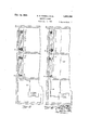
Our invention is full set forth in the following detailed speci cations and drawings forming a part thereof in which latter Figure 1 is a fragmentary vertical section of several floors of a building equipped with our improved system and showing the same in elevation;
Fig. 2 is a fragmentary vertical section partly in elevation of the column enclosing one of the heating units;
Fig. 3 is a transverse section on the line 33 of Fig. 1;
Fig. 4 is a plan view showing one of the radiator elements;
Fig. 5 is a transverse verticalsection' on the line 55 of Fig. 4; v
Fig. 6 is a longitudinal vertical section on the line 6-6 of Fig. 4;
Fig. 7 is a fragmentary horizontal section corresponding-to the line 3-3 of Fig. 1, but showing a modification wherein the heating untiit is applied to a corner of a building; an
'Fig. 8 is a transverse section of a tubular element equipped with vertical radially ex tending fins;
Fig. 9 is a diagrammatic view illustrative of the hook-up of the source of supply of vapor heating medium with the riser carrying the radiator elements interposed therein, whereinbut a single main riser is employed, which is more especially adapted for residential and small oflice buildings, wherein.
the single riser pipe serves both as a supply riser and return flow riser; and
Fig. 10 is a corresponding diagrammatic view illustrative of the hook-up of the source of supply of vapor heating medium with the main rlser carrylng the radiator elements interposed therein, wherein a supply riser is employed to conduct the vapor heating medium to the top of the building and thence the said heating medium is conducted into the top of the said main riser.
Referring to the drawings and the constructure shown therein, a series of casings l which completely enclose the radiator elements hereinafter described are located in recesses 2 preferably formed between the inner and outer walls of the building. Preferably the outer plate a of said casing constitutes a removable cover which is not secured in place when the system is first installed until after the system has been tested. At the bottom and top of the cover plate are an air inlet 3 and an air outlet 4, respectively, which openings admit of the circulation through the casing of air taken directly from the adjacent room which may be freshened if desired by fresh air admitted to the bottom of the ducts through conduits b. The upper air outlet is preferably provided with a register having shutters 5 of the well known construction, adapted to be operated simultaneously to control the amount of air which circulates through the heating unit. v
The radiator elements enclosed by the casing 1 comprise to and bottom header members 6, 6' to whic are welded or otherwise connected tubular elements 7, 7 and 7". These latter elements are each provid ed with a series of obliquely extending fins or vanes 8, 8 and 8", the series 8 extending upwardly to the left at an acute angle, the middle series 8 extending upwardly and rearwardly at a similar angle and the series 8" extending upwardly to the right at alike angle, though obviously the exact angles of inclination are not essential but may vary.
Preferably these fins consist of discs sol dered to or having a forced fit with the tubular elements carrying the same. A convenient form of fin which we preferably employ comprises a disc having a central aperture surrounded by a struck-up flange 9 which projects at oblique angles to the plane of the fin and is adapted to have a snug fit with the tubular element to which the fins are obliquely a plied.
Preferably the top and bottom headers are identical but reversed the same comprising two metal stampings, the upper one having a central aperture surrounded by a marginal struck-up flange 10 which serves for connecting the same to a flared fitting 11 and the other one having three alined apertures surrounded by the struck-up mar- 1nal flanges 12, 12 and 12" which serve or connecting the same to the tubular elements 7, 7 and 7 respectively.
The said fittings 11 serve to connect the respective ends of the radiator elements to the sections 13 or 13 res ectively of the steam riser which, except or the interruptions due to the inter osed heating element projects from the boi er or steam mains in the basement to the uppermost radiator element.
Said riser sections are interconnected with each other by means of flanged tapped unions 14, the respective ends of the abutting sections having opposite threads thereon which admit of the same being threaded into said union. The flanges l4 serve as supports for the various heating units and also to anchor the respective riser sections. Preferably also the riser sections are enclosed in jackets 15 and 15 which are spaced therefrom and afi'ord a layer of air insulation that retards the radiation of heat from the riser sections as such.
While the principal use for our improved system is for heating purposes, it lends itself for employment in summer weather as a cooling system, since it merely requires that the riser pipe be connected also to a source of cooled water or brine supply. In such an event, the metal casing is constructed so as to be water-tight and a drain not shown is provided to draw 03 the water due to atmospheric condensation, the same being either conducted to a common drain Our improved heating system while possessing all of the advantages above enumerated, is extremely simple in construction and consequently of light weight and cheap and is both cheap and easy to install in new buildings or to replace the present types of heating systems in old buildings.
The arrangement of the fins on the tubular elements as herein disclosed effects a thorough distribution of the air as it passes through the radiator element and a maximum of contact between such air and the tubular elements and fins carried thereby. Furthermore, tubular members 7, 7 and 7 may be made from brass or copper or other metal of high heat conductivity, without greatly increasin the cost of manufacture, the heating efi ciency obtainable from our improved system is indeed remarkable.
While we preferably employ obliquely extending fins on the tubular members 7, 7' and 7" and may obviousl employ one or more of such tubular mem rs, nevertheless our invention in its broadest aspect, except insofar as required by certain specific claims is not to be understood as restricted to the particular directions in which the fins extend or as to the number, whether one or more, of tubular radiator elements employed. Furthermore, either transversely extending horizontal or oblique fins or even vertical fins or vanes, such as shown in Fig. 8, may be employed without departing from the spirit of our invention. And so far as the system is concerned, any other form of air modifying units arranged in series in a single riser pipe may be employed within the purview of the invention.
Preferably in the case of large oflice or loft buildings, we conduct the aqueous fluid medium directly from the basement to either the top floor or to an upper intermediate floor level of the building, through a riser 20 and thence from the top of the building or such upper intermediatefloor level, the temperature regulating medium, such for example, as steam or brine, is conducted into the top riser section 13' connecting with the upper header of one of the radiators at such upper level from which it flows downwardly through the other interconnected heating units, in lieu of supplying the temperature regulating medium into the riser 13 communicating with the lowermost radisince the fins, as well as the ator of a series of ertically arranged heating units.
Various other modifications within the scope of the appended claims may also be 5 made without departing from the spirit of our invention.
Having thus described our invention, we claim:
1. In a heating system for multi-story buildings, the combination of a plurality of superposed finned radiators, an upright riser pipe in which said radiators are connected at top and bottom in series, at least one radiator being disposed at each of several of the story levels, and casings for the flow of air enclosing said radiators, each of said casings being formed with intake and discharge openings communicating with the room served thereby.
2. In a heating system for multi-story buildings, the combination of a plurality of finned radiators, a riser pipe in which said radiators are connected in series, at least one radiator being disposed at each of several of the story levels, casings for the flow of air enclosing said radiators, each of said casings formed with upper and lower openings communicating with the room served thereby and means to control the volume of air flowing through each of said casings.
3. In a heating system for multi-story buildings, the combination of a plurality of radiators, each radiator having a plurality of tubular members in communication with each other at their upper and lower ends and each of which tubes is individually equipped with a series of inclined fin elements, a' riser pipe in which said radiators are connected in series, at least one radiator being disposed at each storylevel, casings, for inducing the flow of air, enclosing said radiators, each of said casings being provided with upper and lower openings communicating with an adjacent room served thereb and means to control the volume of air owing through each of said casings. a
4. In a heating system for multi-story buildings, the combination with a source of supply of a vapor heating medium of a vertical riser extending upwardly through the by and means to control the volume of air flowing through each of said casings.
5. In a heating system for multi-story buildings, the combination of a source of aqueous fluid heating medium, a vertical riser extending upwardly through the building, a conduit connecting one end of said riser to said source of supply, a plurality of radiator elements directly interposed in said riser at a plurality of difierent story levels of said building, at least one radiator being disposed at each of several of the story levels, casings enclosing said radiators for inducing the flow of air thereover, each of said casings being provided with upper and lower openings for affording communication with an adjacent room served thereby, means to control the volume of air flowing through each of said casings and a conduit connecting the other end of said riser with said source of supply for returning spent heating medium to said source.
Signed at New York, in the city, county and State of New York, this fifth day of December, 1928.
' DWIGHT D. KIMBALL.
VICTOR J. GUCCI.
building, means for connecting said riser to said source and serving to supply a vapor heating medium to the riser and to return heating medium condensate to said source, a plurality of radiator elements directly interposed in said riser at a plurality of different stories of said building, at least one radiator being disposed at each of several of the story levels, casings enclosing said radiators for inducing the flow of air there'over, each of said casings being provided with upper 'and lower openings for afiording communication with an adjacent room served there-
Priority Applications (1)
| Application Number | Priority Date | Filing Date | Title |
|---|---|---|---|
| US324544A US1897759A (en) | 1928-12-07 | 1928-12-07 | Heating system |
Applications Claiming Priority (1)
| Application Number | Priority Date | Filing Date | Title |
|---|---|---|---|
| US324544A US1897759A (en) | 1928-12-07 | 1928-12-07 | Heating system |
Publications (1)
| Publication Number | Publication Date |
|---|---|
| US1897759A true US1897759A (en) | 1933-02-14 |
Family
ID=23264054
Family Applications (1)
| Application Number | Title | Priority Date | Filing Date |
|---|---|---|---|
| US324544A Expired - Lifetime US1897759A (en) | 1928-12-07 | 1928-12-07 | Heating system |
Country Status (1)
| Country | Link |
|---|---|
| US (1) | US1897759A (en) |
Cited By (1)
| Publication number | Priority date | Publication date | Assignee | Title |
|---|---|---|---|---|
| US2639900A (en) * | 1948-12-11 | 1953-05-26 | Henry G Schaefer | Simplified space heating radiator mounted on pipe |
-
1928
- 1928-12-07 US US324544A patent/US1897759A/en not_active Expired - Lifetime
Cited By (1)
| Publication number | Priority date | Publication date | Assignee | Title |
|---|---|---|---|---|
| US2639900A (en) * | 1948-12-11 | 1953-05-26 | Henry G Schaefer | Simplified space heating radiator mounted on pipe |
Similar Documents
| Publication | Publication Date | Title |
|---|---|---|
| US3526361A (en) | Heating system | |
| US1897759A (en) | Heating system | |
| US2038347A (en) | Air conditioned heating and cooling | |
| US1942432A (en) | Heating apparatus | |
| US2021583A (en) | Device fob conditioning air | |
| US1830719A (en) | Heating device | |
| US2255956A (en) | Dual service heating system | |
| US2176586A (en) | Heating apparatus | |
| US1874940A (en) | Cabinet type unit heater | |
| US1861484A (en) | Concealed heater | |
| US2065708A (en) | Water heater | |
| US2247796A (en) | Heating boiler | |
| US2184095A (en) | Heating and air conditioning apparatus | |
| US1745401A (en) | Water heater | |
| US2588723A (en) | Method of converting air conditioning systems | |
| US2962266A (en) | Air circulating system for cooling | |
| US2307422A (en) | Cooling system for buildings | |
| US2190998A (en) | Air conditioning apparatus | |
| US1768992A (en) | Water-heating apparatus | |
| US1410706A (en) | Heating system | |
| US2087147A (en) | Air conditioning system for | |
| US3236226A (en) | Combined air and water heaters | |
| US1810721A (en) | Heating apparatus | |
| US3315733A (en) | Air conditioning apparatus | |
| US2090208A (en) | Heat exchanger |