US1897453A - Low resistance fluid flow switch - Google Patents
Low resistance fluid flow switch Download PDFInfo
- Publication number
- US1897453A US1897453A US519832A US51983231A US1897453A US 1897453 A US1897453 A US 1897453A US 519832 A US519832 A US 519832A US 51983231 A US51983231 A US 51983231A US 1897453 A US1897453 A US 1897453A
- Authority
- US
- United States
- Prior art keywords
- mercury
- inlead
- switch
- bellows
- fluid flow
- Prior art date
- Legal status (The legal status is an assumption and is not a legal conclusion. Google has not performed a legal analysis and makes no representation as to the accuracy of the status listed.)
- Expired - Lifetime
Links
- 239000012530 fluid Substances 0.000 title description 21
- QSHDDOUJBYECFT-UHFFFAOYSA-N mercury Chemical compound [Hg] QSHDDOUJBYECFT-UHFFFAOYSA-N 0.000 description 42
- 229910052753 mercury Inorganic materials 0.000 description 42
- PXHVJJICTQNCMI-UHFFFAOYSA-N Nickel Chemical compound [Ni] PXHVJJICTQNCMI-UHFFFAOYSA-N 0.000 description 18
- 229910052751 metal Inorganic materials 0.000 description 12
- 239000002184 metal Substances 0.000 description 12
- 229910052759 nickel Inorganic materials 0.000 description 9
- RYGMFSIKBFXOCR-UHFFFAOYSA-N Copper Chemical compound [Cu] RYGMFSIKBFXOCR-UHFFFAOYSA-N 0.000 description 8
- 229910052802 copper Inorganic materials 0.000 description 8
- 239000010949 copper Substances 0.000 description 8
- 239000000463 material Substances 0.000 description 6
- VYZAMTAEIAYCRO-UHFFFAOYSA-N Chromium Chemical compound [Cr] VYZAMTAEIAYCRO-UHFFFAOYSA-N 0.000 description 5
- 229910052804 chromium Inorganic materials 0.000 description 5
- 239000011651 chromium Substances 0.000 description 5
- 238000010276 construction Methods 0.000 description 5
- XEEYBQQBJWHFJM-UHFFFAOYSA-N iron Substances [Fe] XEEYBQQBJWHFJM-UHFFFAOYSA-N 0.000 description 5
- 239000007789 gas Substances 0.000 description 4
- VYPSYNLAJGMNEJ-UHFFFAOYSA-N Silicium dioxide Chemical compound O=[Si]=O VYPSYNLAJGMNEJ-UHFFFAOYSA-N 0.000 description 3
- 230000003247 decreasing effect Effects 0.000 description 3
- 239000005350 fused silica glass Substances 0.000 description 3
- 229910052742 iron Inorganic materials 0.000 description 3
- 150000002739 metals Chemical class 0.000 description 3
- WFKWXMTUELFFGS-UHFFFAOYSA-N tungsten Chemical compound [W] WFKWXMTUELFFGS-UHFFFAOYSA-N 0.000 description 3
- 229910052721 tungsten Inorganic materials 0.000 description 3
- 239000010937 tungsten Substances 0.000 description 3
- 230000008602 contraction Effects 0.000 description 2
- 238000010438 heat treatment Methods 0.000 description 2
- 239000001257 hydrogen Substances 0.000 description 2
- 229910052739 hydrogen Inorganic materials 0.000 description 2
- -1 iron Chemical compound 0.000 description 2
- 238000000034 method Methods 0.000 description 2
- 230000004048 modification Effects 0.000 description 2
- 238000012986 modification Methods 0.000 description 2
- 229910000497 Amalgam Inorganic materials 0.000 description 1
- 101150106671 COMT gene Proteins 0.000 description 1
- UFHFLCQGNIYNRP-UHFFFAOYSA-N Hydrogen Chemical compound [H][H] UFHFLCQGNIYNRP-UHFFFAOYSA-N 0.000 description 1
- 229910000831 Steel Inorganic materials 0.000 description 1
- 238000005267 amalgamation Methods 0.000 description 1
- 230000015572 biosynthetic process Effects 0.000 description 1
- 239000005388 borosilicate glass Substances 0.000 description 1
- 239000004020 conductor Substances 0.000 description 1
- 230000006378 damage Effects 0.000 description 1
- 239000011521 glass Substances 0.000 description 1
- 150000002431 hydrogen Chemical class 0.000 description 1
- 238000007689 inspection Methods 0.000 description 1
- 238000007747 plating Methods 0.000 description 1
- 229910052573 porcelain Inorganic materials 0.000 description 1
- 239000011819 refractory material Substances 0.000 description 1
- 239000010959 steel Substances 0.000 description 1
- 238000006467 substitution reaction Methods 0.000 description 1
Images
Classifications
-
- H—ELECTRICITY
- H01—ELECTRIC ELEMENTS
- H01H—ELECTRIC SWITCHES; RELAYS; SELECTORS; EMERGENCY PROTECTIVE DEVICES
- H01H29/00—Switches having at least one liquid contact
- H01H29/004—Operated by deformation of container
Definitions
- the present invention relates to fluid ilow switches, and especially to switches which are adapted for use in circuits carrying relatively large currents.
- the invention consists in a fluid flow switch of novel construction, and in a novel method of operating Huid flow switches, as herein; after set forth and claimed.
- a particular object of the invention is to provide a fluid flow switch having a relatively high current capacity.
- Anotherpbject of the invention is to provide a switch having a low internal resistance.
- Still another object of the invention is to provide a novel method of operating a fluid flow switch.
- the current rating of electrical switches is determined, as is well known, by two factors; the current which they can safely interrupt, and the current which they can continuously carry without undue heating due to the re- H sistance thereof.
- switches of the fluid flow type the emphasis has been on the rst of these factors, hence in this type of switch the metallic inleads have invariably been spaced a considerable distance apart, in order to permit the arc of rupture to be drawn out sufficiently to extinguish it.
- This construction obviously necessitates the use of a relatively long fluid path to complete the circuit through the switch when it is in a closed cir- "cuit-position. A long fluid pathis, however,
- any of the fluids which are ordinarily used have a relatively high specific r'esistance.
- mercury the fluid almost universally used, has a specific resistance which is approximately twenty times as great as that of tungsten, which is one of the metals commonly used for the inleads of fluid flow and sixty times that of copper.
- the cir,- cuitv is opened or closed in the usual manner by means of fluid flow, and in addition one or more of the electrodes is moved lto reduce the fluid path after the circuit' is closed, and to increase said path again before the circuit is opened, asingle operating means causing these operations to take place in the desired sequence.
- the fluid flow first closes the circuit through a long Huid path and then upon f further movement closes the circuit through a short Huid path of low resistance, these circuits being opened in the reverse order so that the rupturing capacity of the switch is unimpaired. lMy new construction also permits this result to be attained in a switch in which the break occurs between fluid pools.
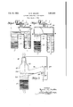
- Fig. 1 is yan elevational view, in part section, of a mercury switch having electrodes which are movable to reduce the distance therebetween during the interval that the circuit through said switch is closed, said switch being shown in a closed circuit position,
- Fig. 2 is a similar view. of the switch of F 1 with the .circuit therethrough open,
- Fig. 3 is an elevational view of a modification of the switchof Figs. 1 and2, which operates in a preferred manner, shown in an" open circuit position.
- a mercury switch having a horizontal tubular body 1 of glass, fused silica or other suitable material.
- tubular extensions or chambers 2 are the tubular extensions or chambers 2 of the same material.
- a sylphon bellows 3 hermetically closes the lower end of each of said extensions. Said bellows is made i vof any iexible metal which will not readily amalgamate with mercury, such as iron,
- nickel, or the like can be made of a metal such as copper, and plated on ⁇ the inside with chromium, nickel, or other metal which does not readily amalgamate with mercury. Due to the thinness of the ⁇ metal it can befused to the lower end of the v'vitreous chambers 2 in a well known manner y regardless of var1at1ons 1n the coeiiiclents of expansion. Where the fusing temperature of 'the vitreous material used for the chambers' 2 is so high that destruction of the meta-l' into the chambers 2.
- inleads may be made of any metal which will not contami nate the mercury, such as tungsten or nickel, but I prefer to use copper which has been plated or otherwise 'coated with chromium, nickel or other metal which will not appreciably contaminate the mercury, due to the relatively low specific resistance thereof.
- tubulation 5 extends from the top of the tubular body 1 to a suitable valve 6, said valve being adaptedgto connect said body 1 either through the tube 7 to a source of an arc suppressing gas such as hydrogen, under pressure, orto the' atmosphere through the pressure relief valve 8.
- a suitable valve 6 said valve being adaptedgto connect said body 1 either through the tube 7 to a source of an arc suppressing gas such as hydrogen, under pressure, orto the' atmosphere through the pressure relief valve 8.
- a quantity of mercury 9 which is suiiicient tocompletely cover the inleads 4 when the sylphon bellows 3 is comt pressed is enclosed within the tubular body 1 and its appendages.
- a lining 10of refractory material such as fused silica, porcelain, or the like Vis placed within the tubular body 1 to shield said body from the arcs of rupture, said lining preferably Jhaving suitable openings therein for movement of the electrodes 4 therethrough, and for the passage of as to or from the tubulation 5.
- a suitable pac g is also provided when desired, between the lining 10 and the bottom of the tubular body 1 to prevent mercury flow therebetween.
- a vertical tubular vchamber 15 of a suitable vitreous material such as fused silica, a .borosilicate glass or the like
- a thin'cup 16 of any suitable metal such as copper whichV has been nickel or chromium plated on the inside to prevent the 195 formation of an amalgam, said cup'being fused to said chamber in a well known manner.
- ⁇ '.lhe lower end of said ,chamber is closed by the sylphon bellows 17, which likewise may be'made of copper or the like, coated on ythe interior. with nickel or chromium; or, if it is desired, said bellows may be made of iron.
- a side chamber 18, of the same material as the chamber 15, extends outwardly and preferably upwardly from the llower part of said chamber 15, a cup 19 being formed in the bottom thereof at the outer end. Said cup retains la mercury pool20,
- Thetubular chamber 15 is likewise filled with mercury 22 to a level, indicatedrby the dashline, which is above that of the pool 20 when said bellows 17 is compressed, the propor- ⁇ tions of the various parts of the device being jsuch that said mercury level is below that of the pool 20, as shown, when said bellows is expanded.
- a heavy inlead 23 which passes through the cup 16 and whichis weldedor otherwise hermetically sealed thereto, extends downwardly to apoint which is below the level of 'the mercury 22 when in its upper position, but slightly above the level of the mercury pool 20.
- a second heavy inlead 24 passes through the sylphon bellows 17, being welded or otherwise hermeticallyr sealed to the closed end thereof, said inlead extending upwardly as far as is consistent with its remaining below the' surface of the mercury 22.
- said inleads 23 and 24 they are preferably formed of copper andl then plated or otherwise coated with chromium, nickel or other metal which resists amalgamation.
- the inlead 23 is connected by the wire 25 with the inlead 21, which may be of appreciableresistance,
- a further rise of the mercury 22 causes it to come into contact with the inlead 23, thereby .establishing a relatively short Huid path from the inlead 23 to the inlead 24. Still further collapse of the bellows 17 causes the inlead 24 to move into contact with the inlead 23, ⁇ as indicated by the dash lines in Fig. 3, the mercury 22 forming a perfect contact therebetween.
- the internal resistance of the switch is negligible and its current carrying capacity with a given temperature rise is extremely large, of the order of hundreds of amperes.
- I claim as my invention: lfA mercury switch comprising a sealed envelope, a sylphon bellows forming a cup sealed into the lower wall thereof, an inlead extending within said cup, a second inlead sealed into another part of said envelope, and mercury in said cup by which said inleads l0 may be connected at will by flexing said bellows, said 'bellows being sufficiently flexible to permit further movement thereof to reduce the iluid path between said inleads. 2.
- 'A mercury switch comprising a sealed 15 envelope, a sylphon bellows forming a cup sealed into the lower wall of said envelope, -an inlead extending within said cup, a side chamber sealed to said envelope, an inlead in said side chamber, mercury in said envelope by which saidrinleads may be connected at will bv iexing said bellows, a third inlead ,extending into said envelope and extending downwardly to a point which is just above the level of said mercury when it makes contact with the inlead in. said side chamber, said bellows being sufliciently flexible to'permit x said mercury to be moved into contact with said third inlead at will, said third inlead being permanently connected to the inlead in said side chamber.
- a mercury switch comprising a sealed envelope, a sylphon bellows forming a. cup
Landscapes
- Circuit Breakers (AREA)
Description
Feb. 14, 1933. w. R. WALKER 1,897,453
LOW RESISTANCE FLUID FLOW SWITCH Filed March 3, 1931 INVENTOR Patented vFeb. 14, 1933 UNITED gs'r-A'lEs PATENT OFFICE WARREN R. WALKER, 0F SHORT HILLS, NEW JERSEY, ASSIGNOR TO GENERAL ELECTRIC VAPOR LAMP COMPANY, 0F HOBOKEN,
JERSEY NEW JERSEY, A CORPORATION OF NEW LOW RESISTANCE FLUID FLOW SWITCH Application led March 3, 1931. Serial No. 519,832.
The present invention relates to fluid ilow switches, and especially to switches which are adapted for use in circuits carrying relatively large currents. o
' The invention consists in a fluid flow switch of novel construction, and in a novel method of operating Huid flow switches, as herein; after set forth and claimed.
A particular object of the invention is to provide a fluid flow switch having a relatively high current capacity. Anotherpbject of the invention is to provide a switch having a low internal resistance. l Still another object of the invention is to provide a novel method of operating a fluid flow switch. Other objects and advantages of the invention will appear from the following detailed specification, or from an inspection of thevaccompanying drawing.
, The current rating of electrical switches is determined, as is well known, by two factors; the current which they can safely interrupt, and the current which they can continuously carry without undue heating due to the re- H sistance thereof. In switches of the fluid flow type the emphasis has been on the rst of these factors, hence in this type of switch the metallic inleads have invariably been spaced a considerable distance apart, in order to permit the arc of rupture to be drawn out sufficiently to extinguish it. This construction obviously necessitates the use of a relatively long fluid path to complete the circuit through the switch when it is in a closed cir- "cuit-position. A long fluid pathis, however,
highly undesirable from the standpoint of the second factor mentioned above, due to the fact that any of the fluids which are ordinarily used have a relatively high specific r'esistance. For example, mercury, the fluid almost universally used, has a specific resistance which is approximately twenty times as great as that of tungsten, which is one of the metals commonly used for the inleads of fluid flow and sixty times that of copper. Hence from the standpoint of minimum internal resistance, and thus of minimum heating, it -is obvious that the fluid path between inleads should be as short as possible, especially since the effective conducting area of the for this purpose heretofore I have now discovered that thislimitatioii can be overcome by means of a novel construction of my invention, which operates in a unique manner to give a minimum fluid path without necessitating any corres onding reduction ofthe path of the arc o rupture. Accordingvto my new invention the cir,- cuitv is opened or closed in the usual manner by means of fluid flow, and in addition one or more of the electrodes is moved lto reduce the fluid path after the circuit' is closed, and to increase said path again before the circuit is opened, asingle operating means causing these operations to take place in the desired sequence. According to another `feature of my invention the fluid flow first closes the circuit through a long Huid path and then upon f further movement closes the circuit through a short Huid path of low resistance, these circuits being opened in the reverse order so that the rupturing capacity of the switch is unimpaired. lMy new construction also permits this result to be attained in a switch in which the break occurs between fluid pools.
Tolfattain the maximum reduction in the internal resistance of these switches it is necessary to utilize a good electrical conductor for the inleads. In the 'past the metal used for these inleads has invariably been one which would not amalgamate with, andl thereby deleteriously affect, the mercury. Nickel, tungsten, chrome-iron and nickel-steel may be mentioned as examples of the metals used Unfortunately each of these metals has a, relatively high specific resistance, while copper, which is extremely desirable from the standpoint of low resistance, so rapidly contaminates the mercury that it has been impossible to use it. VI have'now discovered, however, that copper may be used in these switches by t-he simple expedient of plating it with a metal, such as nickel orchromium, which does not re y amalgamate with the mercury. Such inleads are especially desirable in switches of my novel construction, where there is never any ydanger of an arc striking thereto.
For the purpose of illustrating my invenl tion I have shown two embodiments thereof in the accompanying drawing in which Fig. 1 is yan elevational view, in part section, of a mercury switch having electrodes which are movable to reduce the distance therebetween during the interval that the circuit through said switch is closed, said switch being shown in a closed circuit position,
Fig. 2 is a similar view. of the switch of F 1 with the .circuit therethrough open,
Fig. 3 is an elevational view of a modification of the switchof Figs. 1 and2, which operates in a preferred manner, shown in an" open circuit position. Y
In the drawing, with particular reference to Figs. 1 and 2, there "is shown` a mercury switch having a horizontal tubular body 1 of glass, fused silica or other suitable material. 'Depending from each ejnd of the aforesaid body are the tubular extensions or chambers 2 of the same material. A sylphon bellows 3 hermetically closes the lower end of each of said extensions. Said bellows is made i vof any iexible metal which will not readily amalgamate with mercury, such as iron,
nickel, or the like; or, if desired, it can be made of a metal such as copper, and plated on `the inside with chromium, nickel, or other metal which does not readily amalgamate with mercury. Due to the thinness of the `metal it can befused to the lower end of the v'vitreous chambers 2 in a well known manner y regardless of var1at1ons 1n the coeiiiclents of expansion. Where the fusing temperature of 'the vitreous material used for the chambers' 2 is so high that destruction of the meta-l' into the chambers 2. These inleads may be made of any metal which will not contami nate the mercury, such as tungsten or nickel, but I prefer to use copper which has been plated or otherwise 'coated with chromium, nickel or other metal which will not appreciably contaminate the mercury, due to the relatively low specific resistance thereof. A
In the'modicationshown in Fig. 3 a vertical tubular vchamber 15 of a suitable vitreous material, such as fused silica, a .borosilicate glass or the like, is closed at its upper end by a thin'cup 16 of any suitable metal, such as copper whichV has been nickel or chromium plated on the inside to prevent the 195 formation of an amalgam, said cup'being fused to said chamber in a well known manner. `'.lhe lower end of said ,chamber is closed by the sylphon bellows 17, which likewise may be'made of copper or the like, coated on ythe interior. with nickel or chromium; or, if it is desired, said bellows may be made of iron. A side chamber 18, of the same material as the chamber 15, extends outwardly and preferably upwardly from the llower part of said chamber 15, a cup 19 being formed in the bottom thereof at the outer end. Said cup retains la mercury pool20,
which covers the inlead 21, which is of anysuitable material, such as tungstens' Thetubular chamber 15 is likewise filled with mercury 22 to a level, indicatedrby the dashline, which is above that of the pool 20 when said bellows 17 is compressed, the propor-` tions of the various parts of the device being jsuch that said mercury level is below that of the pool 20, as shown, when said bellows is expanded. A heavy inlead 23 which passes through the cup 16 and whichis weldedor otherwise hermetically sealed thereto, extends downwardly to apoint which is below the level of 'the mercury 22 when in its upper position, but slightly above the level of the mercury pool 20. A second heavy inlead 24 passes through the sylphon bellows 17, being welded or otherwise hermeticallyr sealed to the closed end thereof, said inlead extending upwardly as far as is consistent with its remaining below the' surface of the mercury 22. In order to minimize thel resistance of said inleads 23 and 24 they are preferably formed of copper andl then plated or otherwise coated with chromium, nickel or other metal which resists amalgamation. The inlead 23 is connected by the wire 25 with the inlead 21, which may be of appreciableresistance,
vif so desired. A hydrogen atmosphere is y connected source of suitable pressure through the tube 9, valve 6 and tubulation 5 into the tubular body 1 of the switch. As the pressure in the switch rises the sylphon bellows expand, retracting the inleads 4 into the chambers 2. A moment later` the mercury also recedes into the chambers 2, the circuit through the switch beinginterrupted as the mercury thus divides into two pools. It will thus be seen that the rupturing distance is determined solely by the spacing of the chambers 2. Furthermore, the relatively high gas pressure which is present at the time of rupture with this mode of operation materially increases the rate at which the arc is quenched. Hence this structure places no limitation on the currents which may be interrupted. In order to close the circuit again it is only necessary to again rotate the valve 6 to the position shown in Fig. 1 to disconnect the tubulation from the tube 7 and connect it with the pressure relief valve 8. The excess gas in the switch thereupon escapes through the tubulation 5, valve 6 and relief valve 8. As the pressure in the switch is thus y decreased the sylphon bellows again contract tion is also aided by the wei ht of the switchv due to their natural resilience. This contracif said switch is supported y the inleads 4, this mode of support being especially desirable since it renders flexible electrical.` connections entirely unnecessary. A spring or other means to assist the contraction of the bellows may also be used if desired. As the bellows contracts the mercury therein is obviously forced into the tubular chamber 1, whereupon the two mercury pools again merge, closing the circuit through the switch. At this moment the inleads 4 are still some distance down in the chambers 2, hence the 'fluid path is relatively long and the internal resistance of the switch relatively high. Further contraction of the bellows 3, how; ever, causes the mercury level to continue to rise, and likewise causes the inleads 4 to extend into the tubular chamber 1, .thereby materially decreasing the length of the fluid path. Since the linternal resistance of the switch is thus decreased'it is obvious that the current carrying capacity for a given tem perature rise is materially increased, despite' the fact that thecurrent rupturing capacity is unimpaired. i'
In the use and operation of the modification of Fig. 3 a somewhat greater use of this principle is permitted. Assuming this switch to be in the open circuit position, as shown, upon the application of mechanical pressure tending to move the inlead 24 toward the inlead 23 the sylphon bellows 17 is collapsed, forcing the mercury 22 upwardly into the chamber 15 and the side chamber 18, the inlead 24 following beneath the surface of said mercury. First of all the mercury 22 merges with the pool of mercury 20, closing the circuit from the inlead 23 through wire 25 and inlead 21, thence through the mercury to the inlead 24. A further rise of the mercury 22 causes it to come into contact with the inlead 23, thereby .establishing a relatively short Huid path from the inlead 23 to the inlead 24. Still further collapse of the bellows 17 causes the inlead 24 to move into contact with the inlead 23,`as indicated by the dash lines in Fig. 3, the mercury 22 forming a perfect contact therebetween. As a result the internal resistance of the switch is negligible and its current carrying capacity with a given temperature rise is extremely large, of the order of hundreds of amperes. Upon release of the pressure applied between the inleads 23 and 24, assuming the switch to be supported by the inlead-23, the resilience of the bellows, or other resilient means, if necessary, plus the weight of the mercury 22 will again expand the sylphon bellows 17, with the result that the inlead 24 is first retracted from the inlead 23,v after which the mercury recedes from the inlead 23. No arc occurs at this time, however, due to the fact that the circuit is still closed through the linlead 21.
yIf the connecting wire 25 has an appreciable while I have shown the'switch of Figs. 1 Y
and 2 as being operated by change of gas pressure, and that of Fig. 3 as being mechanically operated itis obvious that either mode of operation could be used with either switch. It is further to be understood that these switches have been described in detail for purposes of illustration only, it being obvious that various changes, substitutions and omissions, within the scope of the appended claims, ma bemade therein without departing from t e spirit of my invention.
I claim as my invention: lfA mercury switch comprising a sealed envelope, a sylphon bellows forming a cup sealed into the lower wall thereof, an inlead extending within said cup, a second inlead sealed into another part of said envelope, and mercury in said cup by which said inleads l0 may be connected at will by flexing said bellows, said 'bellows being sufficiently flexible to permit further movement thereof to reduce the iluid path between said inleads. 2. 'A mercury switch comprising a sealed 15 envelope, a sylphon bellows forming a cup sealed into the lower wall of said envelope, -an inlead extending within said cup, a side chamber sealed to said envelope, an inlead in said side chamber, mercury in said envelope by which saidrinleads may be connected at will bv iexing said bellows, a third inlead ,extending into said envelope and extending downwardly to a point which is just above the level of said mercury when it makes contact with the inlead in. said side chamber, said bellows being sufliciently flexible to'permit x said mercury to be moved into contact with said third inlead at will, said third inlead being permanently connected to the inlead in said side chamber.
A 3. A mercury switch comprising a sealed envelope, a sylphon bellows forming a. cup
sealed vinto the lower wall thereof, an inlead sealed through the end of said bellows, a side chamber sealed to said envelope, an inlead sealed into a cup in vsaid side chamber, mercury in said envelope by which said inleads may be connected at will by flexing said bellows, a third inlead extending downwardly above the first mentioned inlead to a point which is just above the level ofsaid mercury when it makes contact with the inlead in said side chamber, said bellows being suiciently flexible to permit further movement thereof to move the rstmentioned inlead into contact with said third inlead and to raise said mercury above said point' of Contact, said third) inleadA being permanently connected to the inlead in said side chamber. Signed at Hoboken in the ycounty of Hudson and Statev of New Jersey this 2nd day of n March A.D. 1931.
' WARREN R. WALKER.
Priority Applications (1)
| Application Number | Priority Date | Filing Date | Title |
|---|---|---|---|
| US519832A US1897453A (en) | 1931-03-03 | 1931-03-03 | Low resistance fluid flow switch |
Applications Claiming Priority (1)
| Application Number | Priority Date | Filing Date | Title |
|---|---|---|---|
| US519832A US1897453A (en) | 1931-03-03 | 1931-03-03 | Low resistance fluid flow switch |
Publications (1)
| Publication Number | Publication Date |
|---|---|
| US1897453A true US1897453A (en) | 1933-02-14 |
Family
ID=24069974
Family Applications (1)
| Application Number | Title | Priority Date | Filing Date |
|---|---|---|---|
| US519832A Expired - Lifetime US1897453A (en) | 1931-03-03 | 1931-03-03 | Low resistance fluid flow switch |
Country Status (1)
| Country | Link |
|---|---|
| US (1) | US1897453A (en) |
Cited By (2)
| Publication number | Priority date | Publication date | Assignee | Title |
|---|---|---|---|---|
| US2522236A (en) * | 1948-09-15 | 1950-09-12 | Gen Electric | Zero current, auto exhausting, vacuum circuit interrupter |
| US3582590A (en) * | 1969-03-14 | 1971-06-01 | Marcus P Eubank | Sequential switch devices |
-
1931
- 1931-03-03 US US519832A patent/US1897453A/en not_active Expired - Lifetime
Cited By (2)
| Publication number | Priority date | Publication date | Assignee | Title |
|---|---|---|---|---|
| US2522236A (en) * | 1948-09-15 | 1950-09-12 | Gen Electric | Zero current, auto exhausting, vacuum circuit interrupter |
| US3582590A (en) * | 1969-03-14 | 1971-06-01 | Marcus P Eubank | Sequential switch devices |
Similar Documents
| Publication | Publication Date | Title |
|---|---|---|
| US1875765A (en) | Vacuum switch | |
| US2794101A (en) | Vacuum switch | |
| US2175306A (en) | Container for hydrogen-filled electrical devices | |
| US2773954A (en) | Snap action switch | |
| US1897453A (en) | Low resistance fluid flow switch | |
| US3369094A (en) | Gallium metal contact switch | |
| US2142857A (en) | Vacuum tube | |
| US2740869A (en) | Vacuum switch | |
| US1892538A (en) | Vacuum switch | |
| US1042565A (en) | Vapor electric device. | |
| US1937746A (en) | Mercury switch | |
| US2740868A (en) | Vacuum switch | |
| US2740867A (en) | Vacuum switch | |
| US1882614A (en) | Inclosed mercury switch | |
| US1897454A (en) | Low resistance fluid flow switch | |
| US1826571A (en) | Electrical apparatus | |
| US1598875A (en) | Electrical apparatus | |
| US2303371A (en) | Mercury switch relay | |
| US2232626A (en) | Electric switch | |
| US1696023A (en) | Mercury-arc device | |
| GB1213759A (en) | Improvements in vacuum-type circuit interrupter with contacts containing a refractory metal | |
| US1951161A (en) | Mercury switch | |
| US2076162A (en) | Electric switch | |
| US1978817A (en) | Mercury switch | |
| US1951162A (en) | Time delay mercury switch |