US1859955A - Electric switching and distributing system - Google Patents
Electric switching and distributing system Download PDFInfo
- Publication number
- US1859955A US1859955A US243902A US24390227A US1859955A US 1859955 A US1859955 A US 1859955A US 243902 A US243902 A US 243902A US 24390227 A US24390227 A US 24390227A US 1859955 A US1859955 A US 1859955A
- Authority
- US
- United States
- Prior art keywords
- conductors
- switch
- connection
- sand
- conductor
- Prior art date
- Legal status (The legal status is an assumption and is not a legal conclusion. Google has not performed a legal analysis and makes no representation as to the accuracy of the status listed.)
- Expired - Lifetime
Links
- 239000004020 conductor Substances 0.000 description 67
- VYPSYNLAJGMNEJ-UHFFFAOYSA-N Silicium dioxide Chemical compound O=[Si]=O VYPSYNLAJGMNEJ-UHFFFAOYSA-N 0.000 description 30
- 239000007789 gas Substances 0.000 description 28
- 239000004576 sand Substances 0.000 description 28
- 239000007787 solid Substances 0.000 description 11
- 239000011810 insulating material Substances 0.000 description 10
- 238000009413 insulation Methods 0.000 description 5
- 239000000463 material Substances 0.000 description 4
- 239000002245 particle Substances 0.000 description 3
- 150000001875 compounds Chemical class 0.000 description 2
- 239000003517 fume Substances 0.000 description 2
- 238000012986 modification Methods 0.000 description 2
- 230000004048 modification Effects 0.000 description 2
- 238000007789 sealing Methods 0.000 description 2
- 241000252203 Clupea harengus Species 0.000 description 1
- 101000837192 Drosophila melanogaster Teneurin-m Proteins 0.000 description 1
- 239000006004 Quartz sand Substances 0.000 description 1
- 230000004888 barrier function Effects 0.000 description 1
- 238000010276 construction Methods 0.000 description 1
- 230000002950 deficient Effects 0.000 description 1
- 239000000835 fiber Substances 0.000 description 1
- 230000009969 flowable effect Effects 0.000 description 1
- 239000012530 fluid Substances 0.000 description 1
- 238000004519 manufacturing process Methods 0.000 description 1
- 238000000034 method Methods 0.000 description 1
- 230000001681 protective effect Effects 0.000 description 1
- 239000010453 quartz Substances 0.000 description 1
- 239000000126 substance Substances 0.000 description 1
- 238000013022 venting Methods 0.000 description 1
Images

Classifications
-
- H—ELECTRICITY
- H02—GENERATION; CONVERSION OR DISTRIBUTION OF ELECTRIC POWER
- H02B—BOARDS, SUBSTATIONS OR SWITCHING ARRANGEMENTS FOR THE SUPPLY OR DISTRIBUTION OF ELECTRIC POWER
- H02B1/00—Frameworks, boards, panels, desks, casings; Details of substations or switching arrangements
- H02B1/14—Shutters or guards for preventing access to contacts
Definitions
- MASSACHUSETTS ASSIGNOR TO CONDIT ELECTRICAL MANUFACTURING CORPORATION, OF SOUTH BOSTON, MASSACHUSETTS, A CORPORA- TION OF MASSACHUSETTS ELECTRIC SWITCHING AND DISTRIBUTING SYSTEM Application filed December 31, 1927. Serial No. 243,902.
- This invention relates to electric switching and distribution systems and especially to such systems operated at high potentials.
- the electric switches of the system are of the oil immersed type. When the switches are opened under abormal current conditions they sometimes expell heated oil gases and vapors and flame from the switch casing. The heated gases are fairly good conductors and, when they come in contact with a high tension conductor, establish a conducting path over which a flash over arc can pass.
- a further obj ect of the invention is to provide an insulating and protective structure for the connection between the conductor and terminal of an electric switch or other translating device which includes a mobile body of an insulating material and a container therefor, the material being flowable so that it can be poured into the container around the connection without difliculty and yet will not escape through small openings and will shield the conducting parts of the joint against access by heated gases and will act to cool the hot gases as they attempt to penetrate the mobile body.
- a further object of the invention is to provide sealing means for the connection between two conductors and particularly between a conductor and the terminal of an electric switch, which means consists of a container adapted to surround the joint and the insulated conductors on opposite sides of the joint and a body of sand which fills the container and surrounds the joint and the insulated portions of the conductors adjacent the joint, the container being characterized by being removable from the aforesaid relation so that the connection can be exposed for access.
- a yet further object is generally to improve the construction of electric distribution systems.
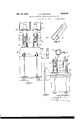
- Fig. 1 is a side elevation partly in section of an electric switching system embodying the invention, parts unnecessary to the understanding of the invention being omitted.
- Fig. 2 is a perspective view of the tubular container for the sand body in which the bare connection between the switch terminal and the conductor is embedded.
- Fig. 3 is a perspective view of one of the retaining springs for the two halves of the tubular container of Fig. 2.
- Fig. 4 is a perspective View of the inventhe conductor bushing, as shown.
- Fig. 5 is a sectional elevation through a switching system embodying the invention wherein the switch is enclosed within a cell and the circuit conductors are extended through the wall of the cell and are shielded against contact with gases and also against passage of gases along the conductors out of the cell in accordance withthis invention.
- Fig. 6 is an enlarged sectional detail of one of the conductors and its insulating shield or bushing of Fig. 5.
- Fig. 1 the oil immersed switch 10 is provided with terminals 12 which are exposed at the tops of the insulating bushings 14. Circuit conductors 16 are connected by suitable joints or connectors 18 with the switch terminals and extending upwardly through insulating bushings 20 into conductor-compartments 24.
- a tubular container 26 which preferably is composed of insulating material, as fibre, surrounds and is spaced from the exposed connector 1'8 and the switch terminal 12 and overlies the lower end of the insulating bushingQO and'the upper end of the switch bushing 14 andrests upon and is supported by the switch and specifically by the switch
- Said body 28 is preferably composed of sand, as a quartz sand, which is free from harmful amounts of forei n material such assilt and conducting metallic compounds.
- the sand is practically impervious to gas and also acts to cool any heated gas that may attempt to penetrate it so that it acts to isolate the exposed conducting elements of the system The sand against access to heated gases.
- the tube 26 is formed of two semi-circular sectionszQGaas shown .in Fig. 2, which sections are held removably in complemented relation .by a pair ofcircular spring olipsi30 which surround the two sections of the tube at the top and bottom thereof and hold them together.
- the clips can be withdrawn and the two halves of the tube separated.
- the sand within the tube can fall to the floor of the switch com artlnent and thus expose the connection.
- the conductor 16a is insulated and maies contact with the switchtenninal 12a through the connector 18a.
- the enclosing tube 26b in this instance rests upon the clamping ring 32 which attaches the bushing 14a to the switch 10a.
- the tube can be raised above its seat and along the conductor 16a. The sand falls out (Ff the bottom of the tube thus uncovering the cennection.
- the tube is placed in its position and sand is poured in through 1; e top of the tube. If necessary, the sand-can be tamped in 1308 although ordinarily this is not essent' Fig.
- FIG. 5 shows a cell enclosed switching system wherein the oil circuit breaker 1.65 is enclosed in a cell 34 provided with a door 36 through which access can be gained to the interior of the cell.
- the (all .13 vented by means of a duct .38 which communicates at one end with the upper portion oi the switdi cell and at its other end with a convenient venting s ace as "the outside atmos here.
- the bare tension conductors 1165M downwardly from an n r room of the switch house and through d: floor of said room, which floor comprises the ceiling ref the switch cell, and into the switch cell, and connect with the switch terminals 12b through connectors 186.
- any gas which may be generated within the switch cell is preventedfrnm escaping into the com partment 39 by means of tubes or shings e2, composed preferably of insulating m terial, which surround said conductors 15b and are extended through openings in and are secured to the floor 40 .anddepe-nd-into the switch cell and are tenm'inated the switch terminals.
- the lower ends cf the tubes are closed by .means of walls 44 her ing openings thereinthr h which the'conductors 161) are passed he tubes are sufficiently large in diameter to ,prevent over from the conductors .to the walls of the tube when the tubes are filled with air.
- a body 46 of sand fillseach tube andthus prevides an eifective barrier against the p: of gas upwardly through the tubes firemt switch cell.
- the connectors 181 are insulated ztram exposure to gas .by the sand filled tubes 250 which rest at their lower ends upon the switch frame and supround the switch bushings, the cmmeetors,
- the conductors 16 and 16?) can be bare since the sand bodies prevent the passage of gases to the conductors and into the upper conductor compartments, the sand body 28 of Fig. 1 sealing the lower end of the passage through the bushing 20, and the sand bodies in the tubes 42 of Fig. 5 preventing passage of gas along the length of the conductors.
- theconductor 16a has an insulating covering which prevents gas from contacting with its conductor and the sand body prevents access of gas to the ex posed elements of the conductor and switch terminal at the joint therebetween.
- the conductor can be covered with a suitable insulation to with stand full line potential.
- the sand-filled enclosing tube 42 can be made smaller in diameter than if the conductors are bare since, in this case it does not have to provide for the insulation of the conductor.
- the sand body thus need be only thick enough to prevent access of gases to the conductor. If a flash over occurs within the tube, and the insulation begins to burn, the fumes of the burning insulation will be entrapped by the sand, and only the gas may escape from the tube, and this gas will be cooled by its passage through the sand. The sand will prevent access of air to the insulation so that any flame will be immediately extinguished.
- the insulating body in the tubes surrounding the conductors preferably is a quartz sandwhich is free from harmful amounts of foreign substances and is of sufficient fineness to resist flow of gases through the sand body or, at least, to cool the gases before they reach the conductors or the atmosphere, as the case may be. 'When the passage through the sand body is long, the sand particles can 'be coarser than when the passage is short.
- sand body for general purposes, in some specific instances the sand may be replaced by an equivalent body that is composed of small discrete insulating and non-combustible solid particles.
Landscapes
- Engineering & Computer Science (AREA)
- Power Engineering (AREA)
- Gas-Insulated Switchgears (AREA)
Description
May 24, 1932.
G. A. BURNHAM ELECTRIC SWITCHING AND DISTRIBUTION SYSTEM Filed Dec. 51. 1927 2 Sheets-Sheet 1 4 Inverfiar.
May 24. 1932.
G. A. BURNHAM Y ELECTRIC SWITCHING AND DISTRIBUTION SYSTEM 2 Sheets-Sheet 2 Filed Dec. 51, 1927 Patented May 24, 1932 GEORGE A. BURN HAM, F SAUGUS,
MASSACHUSETTS, ASSIGNOR TO CONDIT ELECTRICAL MANUFACTURING CORPORATION, OF SOUTH BOSTON, MASSACHUSETTS, A CORPORA- TION OF MASSACHUSETTS ELECTRIC SWITCHING AND DISTRIBUTING SYSTEM Application filed December 31, 1927. Serial No. 243,902.
This invention relates to electric switching and distribution systems and especially to such systems operated at high potentials.
The electric switches of the system are of the oil immersed type. When the switches are opened under abormal current conditions they sometimes expell heated oil gases and vapors and flame from the switch casing. The heated gases are fairly good conductors and, when they come in contact with a high tension conductor, establish a conducting path over which a flash over arc can pass.
y reason of the arrangement of the system it is difficult to extinguish the arc, so that it can cause much damage and disable the system for a long period of time. As a consequence considerable care is exercised in isolating the various conductors ofthe system from each other to prevent the occurence of a flash over. Usually, however the switch terminals, and especially the joint or connection between the conductors and the switch terminals is exposed and, since they are located at the switch, are the most likely parts of the conductorsystem to be bridged by the heated gases and the flash over arc. The joints between the switch terminals and the conductorsare difficult to insulate or to shield from the switch or other conducting gases, for one reason because it is necessary, at times to break the joints and remove a switch. Various insulating and isolating methods have been attempted. If the joint is taped, the tape can not be quickly removed if the switch should suddenly prove defective and should immediately be replaced by a new switch. The tape is combustible and if it is set on fire by an arc burns and gives 011' hot vapors and fumes'which may cause the system to flash over at some point; Oil has been proposed but it is difiicult to make a container which will hold the oil about the joints without considerable dangeriof leakage. The oil more over is combustible and may be set on fire by the flame expelled from the switch or by a flash over in the oil. A hard insulating compound is also inflammable, can not be removed readily and is brittle and liable to crack and thus expose the conductor and provide a path for a flash overare. I
It is an object of the present invention to provide insulating means for the connection between a pair of conductors, and especially for the switch terminal and thereat, which will be free from the above enumerated disadvantages.
A further obj ect of the invention is to provide an insulating and protective structure for the connection between the conductor and terminal of an electric switch or other translating device which includes a mobile body of an insulating material and a container therefor, the material being flowable so that it can be poured into the container around the connection without difliculty and yet will not escape through small openings and will shield the conducting parts of the joint against access by heated gases and will act to cool the hot gases as they attempt to penetrate the mobile body.
A further object of the invention is to provide sealing means for the connection between two conductors and particularly between a conductor and the terminal of an electric switch, which means consists of a container adapted to surround the joint and the insulated conductors on opposite sides of the joint and a body of sand which fills the container and surrounds the joint and the insulated portions of the conductors adjacent the joint, the container being characterized by being removable from the aforesaid relation so that the connection can be exposed for access.
A yet further object is generally to improve the construction of electric distribution systems.
Fig. 1 is a side elevation partly in section of an electric switching system embodying the invention, parts unnecessary to the understanding of the invention being omitted.
Fig. 2 is a perspective view of the tubular container for the sand body in which the bare connection between the switch terminal and the conductor is embedded.
Fig. 3 is a perspective view of one of the retaining springs for the two halves of the tubular container of Fig. 2.
Fig. 4 is a perspective View of the inventhe conductor bushing, as shown.
tion applied to a modified arrangement of switch and conductor.
Fig. 5 is a sectional elevation through a switching system embodying the invention wherein the switch is enclosed within a cell and the circuit conductors are extended through the wall of the cell and are shielded against contact with gases and also against passage of gases along the conductors out of the cell in accordance withthis invention.
Fig. 6 is an enlarged sectional detail of one of the conductors and its insulating shield or bushing of Fig. 5.
In Fig. 1 the oil immersed switch 10 is provided with terminals 12 which are exposed at the tops of the insulating bushings 14. Circuit conductors 16 are connected by suitable joints or connectors 18 with the switch terminals and extending upwardly through insulating bushings 20 into conductor-compartments 24.
I In accordance with this invention a tubular container 26 which preferably is composed of insulating material, as fibre, surrounds and is spaced from the exposed connector 1'8 and the switch terminal 12 and overlies the lower end of the insulating bushingQO and'the upper end of the switch bushing 14 andrests upon and is supported by the switch and specifically by the switch A mobile body 28 of solid insulating and non-combustible material occupies the container 26 and surrounds the joint 18 and switchv terminal 12 and occupies the container about and above the lower end of the bushing 20 and also about and below the top of the switch bushing 14 for such. a distance that "any heated ases' expelled'by the switch or otherwise o1=med can not penetratesaid body and have access 'to the exposed conductor. Said body 28 is preferably composed of sand, as a quartz sand, which is free from harmful amounts of forei n material such assilt and conducting metallic compounds. The sand is practically impervious to gas and also acts to cool any heated gas that may attempt to penetrate it so that it acts to isolate the exposed conducting elements of the system The sand against access to heated gases.
' body although composed of solid particles,
is fluids'o that it can be poured into the -top of the container when the container is in the position shown and thus surround the exposed connection and, insulate it. The sand, however, cannot flow through small'crevices or channels and thus cannot escape from the tubular container'26 at the bottom thereof through amychannels caused ,by irregularitiesofoontact between the bottom of the tube and the bushing 14. V
The tube 26 is formed of two semi-circular sectionszQGaas shown .in Fig. 2, which sections are held removably in complemented relation .by a pair ofcircular spring olipsi30 which surround the two sections of the tube at the top and bottom thereof and hold them together. When the connection is to be inspected the clips can be withdrawn and the two halves of the tube separated. The sand within the tube can fall to the floor of the switch com artlnent and thus expose the connection. W hen the connection is to be recovered the tube can be in its pm vious relation and can be filled with sand.
In the modification shown in Fi l, the conductor 16a is insulated and maies contact with the switchtenninal 12a through the connector 18a. The enclosing tube 26b in this instance rests upon the clamping ring 32 which attaches the bushing 14a to the switch 10a. In this modification when it is desired to expose the connection 180., the tube can be raised above its seat and along the conductor 16a. The sand falls out (Ff the bottom of the tube thus uncovering the cennection. When the connection is recovered the tube is placed in its position and sand is poured in through 1; e top of the tube. If necessary, the sand-can be tamped in 1308 although ordinarily this is not essent' Fig. 5 shows a cell enclosed switching system wherein the oil circuit breaker 1.65 is enclosed in a cell 34 provided with a door 36 through which access can be gained to the interior of the cell. The (all .13 vented by means of a duct .38 which communicates at one end with the upper portion oi the switdi cell and at its other end with a convenient venting s ace as "the outside atmos here. The bare tension conductors 1165M downwardly from an n r room of the switch house and through d: floor of said room, which floor comprises the ceiling ref the switch cell, and into the switch cell, and connect with the switch terminals 12b through connectors 186.. Any gas which may be generated within the switch cell is preventedfrnm escaping into the com partment 39 by means of tubes or shings e2, composed preferably of insulating m terial, which surround said conductors 15b and are extended through openings in and are secured to the floor 40 .anddepe-nd-into the switch cell and are tenm'inated the switch terminals. The lower ends cf the tubes are closed by .means of walls 44 her ing openings thereinthr h which the'conductors 161) are passed he tubes are sufficiently large in diameter to ,prevent over from the conductors .to the walls of the tube when the tubes are filled with air. .A body 46 of sand fillseach tube andthus prevides an eifective barrier against the p: of gas upwardly through the tubes firemt switch cell. As before, the connectors 181 are insulated ztram exposure to gas .by the sand filled tubes 250 which rest at their lower ends upon the switch frame and supround the switch bushings, the cmmeetors,
and also the lower ends of the tubes 42 and thus prevent access of gas to said connectors in the manner above set forth. Said tubes can be moved upwardly about said tubes 4-2 to permit the sand in'said tubes 260 to run outand expose the connectors 18?). In Figs. 1 and 5, the conductors 16 and 16?) can be bare since the sand bodies prevent the passage of gases to the conductors and into the upper conductor compartments, the sand body 28 of Fig. 1 sealing the lower end of the passage through the bushing 20, and the sand bodies in the tubes 42 of Fig. 5 preventing passage of gas along the length of the conductors. In Fig. 4 theconductor 16a has an insulating covering which prevents gas from contacting with its conductor and the sand body prevents access of gas to the ex posed elements of the conductor and switch terminal at the joint therebetween.
In Figs. 5 and 6 the conductor can be covered with a suitable insulation to with stand full line potential. In the latter case, the sand-filled enclosing tube 42 can be made smaller in diameter than if the conductors are bare since, in this case it does not have to provide for the insulation of the conductor. The sand body thus need be only thick enough to prevent access of gases to the conductor. If a flash over occurs within the tube, and the insulation begins to burn, the fumes of the burning insulation will be entrapped by the sand, and only the gas may escape from the tube, and this gas will be cooled by its passage through the sand. The sand will prevent access of air to the insulation so that any flame will be immediately extinguished.
The insulating body in the tubes surrounding the conductors preferably is a quartz sandwhich is free from harmful amounts of foreign substances and is of sufficient fineness to resist flow of gases through the sand body or, at least, to cool the gases before they reach the conductors or the atmosphere, as the case may be. 'When the passage through the sand body is long, the sand particles can 'be coarser than when the passage is short.
While I prefer a sand body for general purposes, in some specific instances the sand may be replaced by an equivalent body that is composed of small discrete insulating and non-combustible solid particles.
I claim:
1. The combination of a pair of conductors having a breakable connection between them, a removable casing surrounding said connection and also said conductors thereat, and a mobile body of solid insulating material contained in said casing and enclosing said connection and the conductors thereat and constituting means to prevent access of a conducting gas to said connection and conductors.
2. The combination of a pair of conductors having a connection between them, a removable casing surrounding said connection and also said conductors thereat, and a mobile body of solid insulating material contained in said casing and enclosing said connection and the conductors thereat and said casing being removable from the aforesaid relation to expose said connection.
3. The combination of a pair of conductors having a connection between them, a remov able casing surrounding said connection and also said conductors thereat, and a body'of sand contained in said casing and enclosing said connection and the conductors thereat and constituting means to prevent access of a conducting gas to said connection and conductors.
4. The combination of a pair of vertical conductors having a connection between them, a vertical casing open at the ends surrounding said connection and also said conductors thereat, means closing the lower open end of said casing, and a mobile body of solid insulating material contained in said casing at and both above and below said connection.
5. The combination of a pair of vertical conductors having a connection between them, a vertical casing open at the ends surrounding said connection and also said conductors thereat, means closing the lower open end of said casing, and a mobile body of solid insulating material contained, in said casing at and both above and below said connection and said casing being removable from the aforesaid relation to expose said connection.
6. The combination of a pair of vertical high tension conductors having a connection between them, insulating means enclosing said conductors on opposite sides of said connection, an open-ended tube surrounding said connection and the insulating means of both conductors, a closure for the lower open end of said tube, and a mobile body of solid insulating material occupying the space in said tube between the ends thereof and about said connection and both insulating means.
7. The combination of a pair of spaced bushings, a conductor extended therebetween and exposed in the space between said bushings, a casing surrounding said exposed conductor and overlying the proximate ends of said bushings, and a mobile body of solid insulating material occupying the space between said conductor and casing and also the space between said bushings and said casing and constituting a gas seal for said conductor, said casing being movable over one of said bushings to expose the conductor extended therebetween.
8. The combination of a depending tube, an insulating bushing spaced below said tube, a conductor extended through said tube and bushing, a mobile body of insulating material contained in said tube about said conductor, a vertical casing surrounding said tube and bushing and the conductor therebetween,
and a mobile body of solid insulating material occupying the space between said casing and tube and bushing, and also between said casing and conductor, said casing being movable 5 upwardly over said tube to expose-said conduetor between said tube and bushing.
9. The combination of enclosing cell having a ceiling providing with an opening therethrough, anoil immersed electric switch contained in said cell, a'high tension conductor extended downwardly through said ceiling-opening and connected with said switch, a tube located in said ceiling-opening about Said conductor and terminated at its lower end close to said switch, and a body of discrete pieces of solid insulating non-combustible material contained in said tube between its ends and in surrounding relation with said conductor and providing a seal preventing escape of hot gases from said cell through said In testimony whereof, I have signed my name to this specification.
GEORGE A. BURNHAM.
Priority Applications (1)
| Application Number | Priority Date | Filing Date | Title |
|---|---|---|---|
| US243902A US1859955A (en) | 1927-12-31 | 1927-12-31 | Electric switching and distributing system |
Applications Claiming Priority (1)
| Application Number | Priority Date | Filing Date | Title |
|---|---|---|---|
| US243902A US1859955A (en) | 1927-12-31 | 1927-12-31 | Electric switching and distributing system |
Publications (1)
| Publication Number | Publication Date |
|---|---|
| US1859955A true US1859955A (en) | 1932-05-24 |
Family
ID=22920599
Family Applications (1)
| Application Number | Title | Priority Date | Filing Date |
|---|---|---|---|
| US243902A Expired - Lifetime US1859955A (en) | 1927-12-31 | 1927-12-31 | Electric switching and distributing system |
Country Status (1)
| Country | Link |
|---|---|
| US (1) | US1859955A (en) |
Cited By (1)
| Publication number | Priority date | Publication date | Assignee | Title |
|---|---|---|---|---|
| US3096391A (en) * | 1960-12-27 | 1963-07-02 | Gen Electric | Bus duct connection |
-
1927
- 1927-12-31 US US243902A patent/US1859955A/en not_active Expired - Lifetime
Cited By (1)
| Publication number | Priority date | Publication date | Assignee | Title |
|---|---|---|---|---|
| US3096391A (en) * | 1960-12-27 | 1963-07-02 | Gen Electric | Bus duct connection |
Similar Documents
| Publication | Publication Date | Title |
|---|---|---|
| BRPI0415386B1 (en) | vacuum switch and method for mitigating electric field distortion within a protected encapsulated vacuum switch | |
| PL202714B1 (en) | Single phase or polyphase switchgear in an enveloping housing | |
| KR920007581B1 (en) | Switch Gear | |
| US1859955A (en) | Electric switching and distributing system | |
| US2273538A (en) | X-ray apparatus | |
| US3035209A (en) | Transformer cover | |
| US3405325A (en) | High tension switching station | |
| US2186377A (en) | Electrical distribution system | |
| US2809259A (en) | Circuit interrupters | |
| US2172640A (en) | Electrical protecting device | |
| US1027404A (en) | Terminal insulator in junction-boxes or the like. | |
| US2039054A (en) | Oil circuit breaker contact | |
| US1748060A (en) | Electric high-tension switching system and apparatus | |
| US1881510A (en) | Method and apparatus for providing the casings of electrical apparatus with inert atmospheres | |
| US1843286A (en) | Switch-house | |
| US3602669A (en) | Purging and drying system for gas blast circuit interrupiers | |
| US2038507A (en) | Electric arc extinguishing medium | |
| GB2471925A (en) | Electrical switchgear | |
| US1878107A (en) | Switch house and switching system and apparatus | |
| RU2857739C1 (en) | Electric arc ionisation suppressor (eais) | |
| US2116676A (en) | Electrical distribution system | |
| US589760A (en) | tailleur | |
| EP0749187B1 (en) | Medium voltage substation with gasinsulated switchgear | |
| JPH0249326A (en) | Vacuum switch | |
| JP2005521225A (en) | Arc resistant enclosure of switchgear |