US1859947A - Rotary bit - Google Patents
Rotary bit Download PDFInfo
- Publication number
- US1859947A US1859947A US54875A US5487525A US1859947A US 1859947 A US1859947 A US 1859947A US 54875 A US54875 A US 54875A US 5487525 A US5487525 A US 5487525A US 1859947 A US1859947 A US 1859947A
- Authority
- US
- United States
- Prior art keywords
- cutter
- bit
- wings
- cutting
- revolution
- Prior art date
- Legal status (The legal status is an assumption and is not a legal conclusion. Google has not performed a legal analysis and makes no representation as to the accuracy of the status listed.)
- Expired - Lifetime
Links
- 238000005520 cutting process Methods 0.000 description 32
- 230000015572 biosynthetic process Effects 0.000 description 24
- 238000005755 formation reaction Methods 0.000 description 24
- 230000033001 locomotion Effects 0.000 description 21
- 238000005553 drilling Methods 0.000 description 14
- 238000009527 percussion Methods 0.000 description 8
- 238000007790 scraping Methods 0.000 description 8
- 239000011435 rock Substances 0.000 description 5
- XLYOFNOQVPJJNP-UHFFFAOYSA-N water Substances O XLYOFNOQVPJJNP-UHFFFAOYSA-N 0.000 description 5
- 238000010276 construction Methods 0.000 description 3
- 238000010586 diagram Methods 0.000 description 3
- 238000005096 rolling process Methods 0.000 description 3
- RTZKZFJDLAIYFH-UHFFFAOYSA-N Diethyl ether Chemical compound CCOCC RTZKZFJDLAIYFH-UHFFFAOYSA-N 0.000 description 2
- 230000003247 decreasing effect Effects 0.000 description 2
- 239000012530 fluid Substances 0.000 description 2
- 238000007689 inspection Methods 0.000 description 2
- 239000000463 material Substances 0.000 description 2
- 241000275031 Nica Species 0.000 description 1
- 241001526284 Percus <genus> Species 0.000 description 1
- 241001417524 Pomacanthidae Species 0.000 description 1
- 238000005299 abrasion Methods 0.000 description 1
- 239000011230 binding agent Substances 0.000 description 1
- 230000006835 compression Effects 0.000 description 1
- 238000007906 compression Methods 0.000 description 1
- 230000007812 deficiency Effects 0.000 description 1
- 230000018109 developmental process Effects 0.000 description 1
- 230000003116 impacting effect Effects 0.000 description 1
- 238000011835 investigation Methods 0.000 description 1
- 239000002245 particle Substances 0.000 description 1
- 230000000717 retained effect Effects 0.000 description 1
- 239000007779 soft material Substances 0.000 description 1
- 230000036346 tooth eruption Effects 0.000 description 1
Images


Classifications
-
- E—FIXED CONSTRUCTIONS
- E21—EARTH OR ROCK DRILLING; MINING
- E21B—EARTH OR ROCK DRILLING; OBTAINING OIL, GAS, WATER, SOLUBLE OR MELTABLE MATERIALS OR A SLURRY OF MINERALS FROM WELLS
- E21B10/00—Drill bits
- E21B10/08—Roller bits
- E21B10/083—Roller bits with longitudinal axis, e.g. wobbling or nutating roller bit
Definitions
- a drillpipe whichdrill pipe extends upwardly through the well and through a. rotar machine on the derr'ck floor of aderric of the well.
- This rotarymachine imparts rotation to thedrill pipe, thus rotating the rotar cutter so as to produce the well.
- the drill7 pipe isv usually supported by -a travelling block which connects with the drill pipe by means of a swivel head- Rotary mud for removing lthe cuttings from the .0 rotary cutter, and for floating the drill pipe.
- a percussion cutter or tool is secured at the lower end of a cable which extends upwardly through the well and is attached to a suitable reciprocating means situated on the lloor of a derrick of the well.
- the tool is elevated by the reciprocating means and allowed to fall sol as to percuss the bottom of the hole and to break the bottom away so as to produce the well. It is customary to keep the'.
- An important consideration of my invention is the fact that it does not produce the hole by attritional action, but produces the hole by a digging or chopping action.
- a bit of my invention cuts .throu h rock', not by scraping or attrition, but by disintegration.
- Investigation tends toV show that certain, of the harder formations are composed of particles which are heldto ether by a binder.
- the action of my bit ten s to sep-A arate'theseparticles by an impacting or percussion action, rather than by a scraping or grindingaction.
- Rotary bits also have marked disadvantages -in'very soft, gummy formations. It is found that as the bit rotates, the scraping action thereof tends to build a mass of the formation directly in front of the cuttingy edges of such bits. As the cutting continues, these masses become quite large and do not mix readily with the rotary ⁇ mud andare, therefore, not carried away from the cutting edges as they -should be or as is intended. These large masses offer enormous resistances to the rotation of the bit and seriously interfere with the cutting thereof. It is alleged that many of the twistolis, that is, a twisting olf in the drill pipe, result from the enormous re- 10o times means an entire loss of the well in hole.
- a thorough mixing of cuttings with water entirely prevents the formation of a mass-adjacent to the cutting edges and eliminates the resistance to the cuttin as in the ordinary types of fishtail bit. his also reduces the power required .tov operate the bit By thoroughl mixing the cuttings with water, they are-rea carried away, and the elcient operation il of, the bit will not ⁇ be impeded.
- the bit of my invention operates or cuts in such a manner that there 1s no side pressure against the walls of the hole as in the ordinary types of bit, and there-V fore there are no stralns placed thereon which would tend to cause cave-ins.
- the blt of my invention is of such a construction that the resistance placed against the cutter thereof is transferred to the drill pipe in such a manner thaty the drill pipe is placed under compression rather than subjected to atwisting action. It is also constructed in such' a manner that in the event the cutter becomes jammed, there will be nonoticeable twisting action on the drill pipe andthe drill pipe will move up and down as it rotates. viding a bit having a cutter which is not rigidlyhsecured vto the body.
- e percussion system of drilling wells is applicable'substantiallyentirely to hard formations, this s stem being exceptionally well suited for roc effectively penetrated by percussion.
- cable tools that is, tools employed in the percussion system of drilling wells,reach a soft formation
- the cutting action is very inellective.
- the cable tool is dropped into a softer formation,fit naturally I accomplish this by proformations which are most 'raising the cable tool, it is necessary to pull the toolfrom the formation. As the tool is raised, a considerable suction or vacuum is created below the tool, which greatly opposes an upward motion thereof.
- the fluid pressure in the well- is 3000 pounds per square inch, it is obvious that the power necessary to elevate this tool is enormous.
- the percussion of the cable tool against the soft formation would not be effective in drilling a hole, as this formation is not chipped away or disintegrated as in the case of rock.
- the blades or teeth of thecutters move in a reciprocating manner, but also have a sideward motion whicheliminates any suction that resists the raising of said blades. ⁇ It is effective in producing the hole, dueto the fact that it tends tovforce the cuttings inwardly, so lthat they-may be readily mixed with water and moved away from the cutter.
- a cutter engages the bottom of the well and is rotatably mounted on the lower end of the drill pipe on an axis oblique to that of thedrill pipe.
- the cutter is given a gyratory movement causing itto have a rolling action upon the bottom of the well.
- a large number of relatively shallow teethl provided on the rolling surfaces of the cutter are thus caused to abrade the bottom of the well and gradually wear this away.
- a gyratory cutter having a relatively small number of relatively large downward extending teeth which form a central concave depression in the bottom of the well which guides and controls the action of the bit. I have found that these teeth, if.
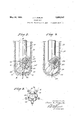
- Fig. 1 is a diagrammatic view illustrating the utility of my invention.
- Fig. 2 is an enlarged partially sectioned view of a rotaryy bit providing the features of my invention, the bit shown in Fig. 2 being a type of bit having five wings, each of which has a plurality of teeth.
- Fig. 3 is a bottoml plan view of the cutter of the bit shown in Fig. 2.
- Fig. 4 is an enlarged view ofthe bit shown in Figs. 2 and- 3, this view illustrating various positions of the ⁇ cutter of the bit,
- Fig. 5 is a plan view showing the contour of the bottom of a hole being produced by a bit of myv invention..
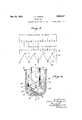
- Fig. 7 isan extremely diagrammatic development showing relative movement between .the cutter and the shank of the bit and illustrating the manner of cutting of the cutter.
- Fig. 8 isa diagrammatic view illustrating the motion of the cutting wings of the cutter bit of my invention.V
- Fig. 9 is a view of the bit of my invention being provided in an alternative form.
- Fig. 1 of the drawings show a bit 50 embodying the features of my invention attached at the lower end of a drill pipe 51 which extends upwardl througha well. 52, through the floor of a errick 53, and being supported b a suitabletravelling block 54.l A rotar ta le 55 is provided on the iioor of the errick 53 for the purpose of rotating the drill pipe 51, lthus imparting rota-- tion to the bit 50 of my inventxon. The details of construction of the bit 50 are clearly shown in Figs. 2 to 8, inclusive, of my invention.
- the bit 50 provides a body or shank which is secured at the lower end of the drill pipe 51, saidshank being concentric 5 on an axis of rotation A-A which is the axis Fig. 6 is a diagrammatic view illustrating of rotation of the drill pipe 51.
- an eccentric formation or foot 61 having an angular lower face 62.
- An angular pin 63 is threaded into an opening 64 formed in the eccentric foot 61 and extending upwardly thereinto from the lower angular face 62.
- a cutter 65 is carried by the angular pin 63.
- This cutter 65 h-as a hub or body 66 having an opening 6 7 through which the pinv .63 extends, said pin 63 having a head 68 by virtue of which the 'cutter 1s retained in place.
- VExtending ⁇ from the hub or body 66 of the cutter 65 are -a plurality ⁇ of cutter wings 70 which are preferably of radial extension and equally spaced, as shown clearly j in Fig. 3.
- the bit 50 is shown as having a cutter 65 provided ,with five cutter wings 70. Each of the cutter Wings 70 provides teeth 71 and 72.
- the axis of rotation of the cutter 65 is disposed on an axis B-B which as clearly shown in Fig. 2 is at an angle with respect to the axis of rotation ⁇ A-A of the body 60.
- the bit of my invention by virtue of its constructionv operates in such a manner as to possess various-important features.
- the cutter 65 ismov-ed through a reciprocating motion which accomplishes the cutting of the hole and passes through a rotating movement, which moves the cutting edges in such a manner that the cutter will produce a round hole.l
- the ratio of rotation between the cutter andthe body is one to five, that is to say,there willbe one revolution of the cutter at live-revolutions of the body.
- iral line 8O representsrevolutions of the bod)y 60 of the cutter
- the line 81 represents the orbit of a wing 70 of the cutter 65.
- the rotation of the bit is divided into eight equal parts by radius lines 82.
- Fig. 5 is a plan view showing the bottomof a hole cut by abit of my invention. By 1ns ection of this figure, it will be seen that t ere are outer and inner ledges 85 and 86.
- these ledges are symmetric, being of even shape and size.
- the outer ledge 85 is cut'by upper teeth 71 of the cutter wings 70 and the inner ledge 86 is cut by lowert-eeth 72 of the wings 70.
- the outer ledge 8,5 is 0f V-shaped formation, as shown, this being due to theI fact that the wings 70 pivotsubstantiall-y at the cutting edge of the teeth 71. Because of the pivoting at this oint, the lower tooth 72 of each of the wings e 0 is caused to swing through a circular path,
- Fig.,7 is solely for illlustration, and either of the ledges 85 and 86 ,indicated by points 0,4 10, 2o, 30 and 40 in Fig. 6.
- the cutter actually moves slightly less than a quarter of a revolution, as indicated by 0 to 10 in Fig. 6.
- 0 to 40 represents five revolutions of the body and one revolution of the cutter. VFive-eighths of a revolution of the body moves the cutter substantially one-eighth of a revolution or from 0 to 5, this motion constituting an upward stroke of a reciprocation.
- the cutter travels substantially another eighth of a revolution, the cutter moving through its downward stroke of a reciprocation; however, in actual practice the cutter revolves slightly less than .one-fourthof a revolution when the body has revolved one and one-fourth revolutions.
- either of the teeth '71 and 72 will cut away surfaces 88 of either of the ledges 85 or 86, as indicated by dotted lines 93 of Fig. 7. This indicates that the cutting of the ledges takes place on one side only, 4the other sidefof the ledges being formed at a termination of a toothof a wing of the cutter.
- any ofthe-teeth l also extend in a vertical direction as indicated at 100 in Fig. 8.
- a wing or tooth extends at right angles to the angle of the face 62 of the body 6 0 as indicated at 101. It is evident then that during the downward stroke of a reciprocation, a tooth swings from vertical position through a series of 'positions into the position showln in 101, and then swings again into vertical position.
- a wing or tooth swings from vertical position into an angular position 103 through a position 104 and into a vertical position 105. Further, it will be seen from Fig. 8 that the wings 70 106, this accounting'for the formation of the cavities 87. In passing through' this ⁇ swinging motion, during a complete reciprocation, the wings form the rounded portions 97 shown in Fig. 5.
- the lawful motionof a cutter connected with the body 60, as shown and described, depends upon the position ofthe cutter, and the number of wings of the cutter.
- the distance of reciprocation. of the wings of the cutter is governed by the angle between vthe axes A-A and B-'-'B.
- the reciprocating travel of the wings 70 may be increased.
- the reciprocating travel of these wings may be decreased.
- the ratio of rotation between the body 60 and the cutter 65 may be varied by changing the 'number of wings 70. In the drawsl ings the ratio between the body 60 and the cutter vis five to one, this being due to the fact that the cutter 65 has five wings 7 0.
- the ratio of rotation between the cutter and the body 60 may be varied. For example, a cutter with four wings would have a ratio of one to four; a cutter vwith six wings would have a ratio of one to six with the body 60.2 From this it is evident that by varyingA the angle and by changing the number of' wings, abit suitable for any formation may be provided.
- the wings 70 may be likened to andl described as chisels or picks in order to distinguish them from other forms of cutters on gyrating bits previously known in the art.
- gyrating bits previously devised anV exceedingly large number of cutting teeth were provided which lwere disposed close together so as'to form an abrasive or grinding surface.
- my cutters are relatively few in number and spaced a relatively large distance apart so that each operates in an independent manner entirely absent in the gyrating bits previously known.
- a bit of my invention produces a. hole by a digging or ,disintegrating action and not by a scraping or attritional action as in the case of the present types'of rotation bit. For this reason the wear thereupon ,in hard materials is a minimum and the speed at which it cuts is a maximum.
- the bit of my invention is very successful in gummy formations, due to the factthat by virtue of its motion a mass will not collect on the cutting edges, and cuttings will be readily mixed with water so that there will be no such oppoi sition to the cutting progress ofthe drill. With reference to Fig.
- a bit 115 which is very similar to the bit shown in the other fi res of the drawings. However, by inspection it will vbe seen that this bit has a cutter 116 having five wings 117, each wing having one cutting edge 118. In other words, each wing 117 comprises a tooth. The bottom of the hole being cut by the bit 115 is of slightly different contour than the bit 50.
- the cutter 116 is secured at angles to the axis of rotation of a body 119 by means of a pin 120 which extends into an eccentric foot 121 of the body 119, as shown.
- a body adapted to be secured to "a d rillpipe and to be rotated thereby; alcutter rotatably supported by said body on an axis inclined downwardly and inwardly towards the axis of rotation of said body; and cutter ⁇ b1ades projecting downwardly from said cutter, eac
- each of saidv cutter blades having a plurality of digging points and an outer curved face connecting to one of said digging points and adapted to engage the side wall of the hole.
- a body adapted to be secured to a drillpipe and to be rotated thereby; a cutter rotatably supported by said body on an axis inclined downwardly and inwardly towards the axis of rotation of said body; and cutter blades rojecting downwardly from said lli of said cutter blades having a plurality of digging points, and Aan outer curved face connecting to each of said-digging oints.
- a well drilling bit the combination of: a body adapted to-be secured to a drillpipe and to be rotated thereby; a cutter rotatably supported by said body'on an axis inclined downwardly and inwardly towards ging oints below said cutter; and means providing circumferentially spaced outer digging points below said cutter and outside said inner digging points, and outer curved faces connecting to said outer digging points, said outer curved faces being generated around a point at the center of motion of the bit and having'scraping contact with the side wall of the well being ⁇ drilled.
- each of said cutter blades projecting downwardly from said cutter, each of said cutter blades having inner and outer digging points, and an outer curved face connecting to the outer of said digging points.
- a body adapted to be secured to a drillpipe and to be rotated thereby; a cutter rotatably-supported by said body on an axis inclined downwardly and inwardly towards the axis of rotation of said body; means providing clrcumferentially spaced inner digging points below said cutter; and means provldlng circumferentially spaced outer digging points below said cutter and outside said inner digging po'ints, and ⁇ outer curved faces connecting to said outer digging points and adapted to engage the side wall of the hole". 5.
- a body adapted to be secured to a drillpipe and to be rotated thereby; a cutter rotatably-supported by said body on an axis inclined downwardly and inwardly towards the axis of rotation of said body; means providing clrcumferentially spaced inner digging points below said cutter; and means provldlng circumferentially spaced outer digging points below said cutter and outside said inner digging po'ints, and ⁇ outer curved faces connecting to said outer digging points and adapted
Landscapes
- Engineering & Computer Science (AREA)
- Life Sciences & Earth Sciences (AREA)
- Geology (AREA)
- Mining & Mineral Resources (AREA)
- Mechanical Engineering (AREA)
- Physics & Mathematics (AREA)
- Environmental & Geological Engineering (AREA)
- Fluid Mechanics (AREA)
- General Life Sciences & Earth Sciences (AREA)
- Geochemistry & Mineralogy (AREA)
- Earth Drilling (AREA)
Description
May 24, 1932- J. A. ZUBLIN 17,859,947
ROTARY BI T Original Filed Sept. 8, 1925 4 Sheets-Sheer. 1
rroffvfy.
J. A. ZUBLIN ROTARY BIT May 24, 1932.
original Filed sept. 8, 1925 `4 Sheets-Sheet 2 Jf//v i. ZaL/N,
irre/WYE?.
J. A. ZUBLIN May 24, 1932.
ROTARY BIT 4 Sheets-Sheet Original Filled Sept. 8, 1925 Patented May 24, 1932 UNITED STATES PATENT OFFICE l JOHN ZUBLIN, OF LOS ANGELES, CALIFORNIA, ASSIGNOR '10 UNIVERSAL ENGINEER- ING COMPANY, F LOS ANGELES, A CORPORATION OF CALIFORNIA 'Apalicaann nica september s, 1925, smal no. 54,875. Renewed November 16, 1929.
w of a drillpipe, whichdrill pipe extends upwardly through the well and through a. rotar machine on the derr'ck floor of aderric of the well. This rotarymachine imparts rotation to thedrill pipe, thus rotating the rotar cutter so as to produce the well. The drill7 pipe isv usually supported by -a travelling block which connects with the drill pipe by means of a swivel head- Rotary mud for removing lthe cuttings from the .0 rotary cutter, and for floating the drill pipe.
away from the sides of the hole so as to reduce friction, is introduced into the drill pipe by lmeans of'high pressure pumps which connect with the swivel head by means of a stand pipe and a flexible hose. Rotary mud' is pumped downwardly through the drill pipe and passes out of the rotary cutter or rotary drill adjacent lto. the cutting edges thereof. In the percussion system bf drilling wells a percussion cutter or tool is secured at the lower end of a cable which extends upwardly through the well and is attached to a suitable reciprocating means situated on the lloor of a derrick of the well. The tool is elevated by the reciprocating means and allowed to fall sol as to percuss the bottom of the hole and to break the bottom away so as to produce the well. It is customary to keep the'.
40 well being drilled full of rotary mud or water. l
Both of these systems have their advantages in certain formations, the rotary system being suited for softer formations and 45 the percussion system being suited for the harder rock and shale formations. Both of these systems, however, have deficiencies which are overcome in my invention.
In the rotary system the cutters or bits 5') employed cut entirely by scraping or-attritional action, that is to say, the cutting edges are moved over the surfacebeing cut 'at substantially right angles to the plane thereof. The principle of operation or the manner of cutting of rotary cutters is substantially the same, although there are various forms of rotary bits. l-
When rotary bits arrive at harder formations, su'ch as shale or rock, much difficulty is experienced. The cuttingA of the bit is'very slow, andthe wear on the cutting edges is enormous. The reason'forsuch slow cuttingl and excessive wear is the manner of opera.-
tion of the blades. These blades, due to their i cutting by scraping or attrition, are sub- 015v jected to considerable attrition themselves. When drilling through rock with rotary tools, the wear thereon is so great that they must be re laced at very frequent intervals.
It is an o ject of m invention to provide a bit which will cut etlectivel and rapidly in hard formations such as roc and shale. An important consideration of my invention is the fact that it does not produce the hole by attritional action, but produces the hole by a digging or chopping action. In other words, a bit of my invention cuts .throu h rock', not by scraping or attrition, but by disintegration. Investigation tends toV show that certain, of the harder formations are composed of particles which are heldto ether by a binder. The action of my bit ten s to sep-A arate'theseparticles by an impacting or percussion action, rather than by a scraping or grindingaction.
Rotary bits, also have marked disadvantages -in'very soft, gummy formations. It is found that as the bit rotates, the scraping action thereof tends to build a mass of the formation directly in front of the cuttingy edges of such bits. As the cutting continues, these masses become quite large and do not mix readily with the rotary` mud andare, therefore, not carried away from the cutting edges as they -should be or as is intended. These large masses offer enormous resistances to the rotation of the bit and seriously interfere with the cutting thereof. It is alleged that many of the twistolis, that is, a twisting olf in the drill pipe, result from the enormous re- 10o times means an entire loss of the well in hole.
event that .the portion of the drill pipe twisted oi becomes stuck or lodged in such a manner that it cannot-be freed and removed from the y The ordinary form of shtail bit exerts considerable pressure against the walls of the well. This is due t0 the scraping manner of cutting, and also due to the building up of the formation in ,front of the cutting edges. This side pressure very often results in caveins which are sometimes disastrous.
It is an object of my invention to provide a bit which is so constructed that the cuttings thereof are thoroughly and readily mixed with reciprocating mud and carried away from the cutting .edges thereof. A thorough mixing of cuttings with water entirely prevents the formation of a mass-adjacent to the cutting edges and eliminates the resistance to the cuttin as in the ordinary types of fishtail bit. his also reduces the power required .tov operate the bit By thoroughl mixing the cuttings with water, they are-rea carried away, and the elcient operation il of, the bit will not` be impeded.
It is a further` object of my invention to provide a bit, the operation of which will not conduce to cave-ins. The bit of my invention operates or cuts in such a manner that there 1s no side pressure against the walls of the hole as in the ordinary types of bit, and there-V fore there are no stralns placed thereon which would tend to cause cave-ins. Y
It is a further object of my invention to provide a bit of the character mentioned in which it will not be impossible for such bit to cause a twistoif of the drill pipe, due to a jamming of the cutter. The blt of my invention is of such a construction that the resistance placed against the cutter thereof is transferred to the drill pipe in such a manner thaty the drill pipe is placed under compression rather than subjected to atwisting action. It is also constructed in such' a manner that in the event the cutter becomes jammed, there will be nonoticeable twisting action on the drill pipe andthe drill pipe will move up and down as it rotates. viding a bit having a cutter which is not rigidlyhsecured vto the body.
e percussion system of drilling wells is applicable'substantiallyentirely to hard formations, this s stem being exceptionally well suited for roc effectively penetrated by percussion. When cable tools, that is, tools employed in the percussion system of drilling wells,reach a soft formation, the cutting action is very inellective. For example, when the cable tool is dropped into a softer formation,fit naturally I accomplish this by proformations which are most 'raising the cable tool, it is necessary to pull the toolfrom the formation. As the tool is raised, a considerable suction or vacuum is created below the tool, which greatly opposes an upward motion thereof. Considering that the fluid pressure in the well-is 3000 pounds per square inch, it is obvious that the power necessary to elevate this tool is enormous. Likewise, it is seen that the percussion of the cable tool against the soft formation would not be effective in drilling a hole, as this formation is not chipped away or disintegrated as in the case of rock.
It is an object of my invention to provide a bit which cuts by a reciprocating action but does not have the disadvantages present in the cable tools when such toolsare drilling in soft formations. In my invention the blades or teeth of thecutters move in a reciprocating manner, but also have a sideward motion whicheliminates any suction that resists the raising of said blades.` It is effective in producing the hole, dueto the fact that it tends tovforce the cuttings inwardly, so lthat they-may be readily mixed with water and moved away from the cutter.
It is another object of my inventionto providera bit of the character mentioned which will drill alarge hole and require only a comparatively small drill pipe to operate same. This'is possible due to the fact that the construction of my invention allows the drill pipe to rotate at a much greater speed than the cutter. Forvthis reason the strain placed upon the drill pipe is greatly reduced, as compared with the strain which would be placed thereonwere the cutter 'rotated at the same rate of speed as the drill pipe.
In a certain type of rotary bit for drilling deep Wells, a cutter engages the bottom of the well and is rotatably mounted on the lower end of the drill pipe on an axis oblique to that of thedrill pipe. Thus, whenthe drill pipe rotates, the cutter is given a gyratory movement causing itto have a rolling action upon the bottom of the well. A large number of relatively shallow teethl provided on the rolling surfaces of the cutter are thus caused to abrade the bottom of the well and gradually wear this away.
It is another object of my invention to provide a bit of the gyratory type in which the cutting action is much faster than when this action is merely one of abrasion.
In accomplishing the foregoing object, I have provided a gyratory cutter having a relatively small number of relatively large downward extending teeth which form a central concave depression in the bottom of the well which guides and controls the action of the bit. I have found that these teeth, if.
properly formed, will cause the cutter to assume a motion in said concave depression similar in character to that of the ball to the socket in a ball-and-socket joint and that such a motion greatly increases the, cutting -action of the bit over the rolling motion used 1n former gyratory bits.
It is therefore an object of my invention to provide a gyratory bit cutter with teeth lO which are formed in a manner tol cause the cutter to assume a ball-and-socket motion in a depression dug by said teeth'. n
Other objects and important advantages of my invention will be presented herein` after. l
Referring to the four sheets of drawings in which I diagrammatically delineate 4my lnvention,
Fig. 1 is a diagrammatic view illustrating the utility of my invention.
Fig. 2 is an enlarged partially sectioned view of a rotaryy bit providing the features of my invention, the bit shown in Fig. 2 being a type of bit having five wings, each of which has a plurality of teeth.
Fig. 3 lis a bottoml plan view of the cutter of the bit shown in Fig. 2.
Fig. 4 is an enlarged view ofthe bit shown in Figs. 2 and- 3, this view illustrating various positions of the `cutter of the bit,
Fig. 5 is a plan view showing the contour of the bottom of a hole being produced by a bit of myv invention..
movements between the cutter and the's'hank of the bit of my invention shown'in Figs."
1 to 4 inclusive.
Fig. 7 isan extremely diagrammatic development showing relative movement between .the cutter and the shank of the bit and illustrating the manner of cutting of the cutter. A
Fig. 8 isa diagrammatic view illustrating the motion of the cutting wings of the cutter bit of my invention.V
Fig. 9 is a view of the bit of my invention being provided in an alternative form.
In Fig. 1 of the drawings,` I show a bit 50 embodying the features of my invention attached at the lower end of a drill pipe 51 which extends upwardl througha well. 52, through the floor of a errick 53, and being supported b a suitabletravelling block 54.l A rotar ta le 55 is provided on the iioor of the errick 53 for the purpose of rotating the drill pipe 51, lthus imparting rota-- tion to the bit 50 of my inventxon. The details of construction of the bit 50 are clearly shown in Figs. 2 to 8, inclusive, of my invention. With reference to these figures, the bit 50 providesa body or shank which is secured at the lower end of the drill pipe 51, saidshank being concentric 5 on an axis of rotation A-A which is the axis Fig. 6 is a diagrammatic view illustrating of rotation of the drill pipe 51. At the lower end of the shank 60 is an eccentric formation or foot 61 having an angular lower face 62. An angular pin 63 is threaded into an opening 64 formed in the eccentric foot 61 and extending upwardly thereinto from the lower angular face 62.
A cutter 65 is carried by the angular pin 63. This cutter 65 h-as a hub or body 66 having an opening 6 7 through which the pinv .63 extends, said pin 63 having a head 68 by virtue of which the 'cutter 1s retained in place. VExtending `from the hub or body 66 of the cutter 65 are -a plurality `of cutter wings 70 which are preferably of radial extension and equally spaced, as shown clearly j in Fig. 3. The bit 50 is shown as having a cutter 65 provided ,with five cutter wings 70. Each of the cutter Wings 70 provides teeth 71 and 72. The axis of rotation of the cutter 65 is disposed on an axis B-B which as clearly shown in Fig. 2 is at an angle with respect to the axis of rotation `A-A of the body 60.
The bit of my invention, by virtue of its constructionv operates in such a manner as to possess various-important features. When the body 60 of the"bit is rotated, the cutter 65 ismov-ed through a reciprocating motion which accomplishes the cutting of the hole and passes through a rotating movement, which moves the cutting edges in such a manner that the cutter will produce a round hole.l
' The reciprocating motion of the cutter 65 is clearlyshown in Fig. 4 of the drawings. -The 'full lines in this figure show the position of the parts when the shank 60 has moved half a revolution with respect to the showlng 1n Fig. 2. Itis evident that the cutter 65 has beenl swung so as to be at an angle to` the opposite sidev of the axis A-A equaly tothe angle at which it rested in Fig.2. When the l.lower portion 75 of the face 62 of the body -60 rests adjacent to a wing 7 0, such wing 1s at the lower end of its'stroke, and when an upper portion 76 of the face 62 is adjacent to a wing 70, such wing is at the upper end of its stroke. Therefore, as the body rotates, the upper and lower portions move into the adjacency of the wings 70, forcing them up and down. The -ratio of rotation between the body of the bit and the cutter is determined by the number of wings 70 of the cutter. This has Abeen found to be true by experiment.-
For example, with a cutter of five teeth, the ratio of rotation between the cutter andthe body is one to five, that is to say,there willbe one revolution of the cutter at live-revolutions of the body. This is clearly illustrated in the diagram shown in Fig. 6. A In Fig. 6 as iral line 8O representsrevolutions of the bod)y 60 of the cutter, andthe line 81 represents the orbit of a wing 70 of the cutter 65. The rotation of the bit is divided into eight equal parts by radius lines 82.
Considering that the bit rests in the position shown in Fig. 2, the lower tooth 7 2 of a wing 70 of the cutter 65 rests at a point 0 on the orbit 81', and the lower portlon 75 of the face 62 rests at a point 0 on the spiral line 80. As the body rotates, the point 75 moves consecutively through the points through a point 40', having completed five entlre revolutions. A point on ya tooth 72 during these live revolutions of the 'body 60 moves through points 0 to 40 on theorbit 81. lVhen the `portion 75 of the body moves from 0 to 1', a.
point on a tooth 72 moves from 0 to 1 on the line 81." When the body has moved a revolution and a quarter to a point on the line 82 1ndicated by 10', said point on the cutter has moved through substantially one quarter of a revolution, reaching a point 10 on the orbit 81. VV-hen the body has revolved another revolution and a quarter, arriving at a point the point on the cutter has completed sub# stantially another quarter of `a revolution, arriving at a point 20 on the line 81. When said point on the body moves another revolution and a quarter, arriving at a point said point on the cutter has movedV a third quarter 0f a revolution, arriving at a oint 30. Another revolution and a quarter of the body moves said point of said body to a point which completes ive entireirevolutions of the body, and said point on said cutter moves from the point 30 tothe I point 40 on the orbit 81,`completing one entire revolution. The diagram in Fig. 6 clearly and accurately shows corresponding positions of the mentioned points on the body, and the cutter at degrees of angular rotation of the body 60. The lower tooth 72 of each ofthe wings 70 passes through a peculiar motlon, as indicated by the orbit 81.
Fig. 5 is a plan view showing the bottomof a hole cut by abit of my invention. By 1ns ection of this figure, it will be seen that t ere are outer and inner ledges 85 and 86.
Further, it will be seen that these ledges are symmetric, being of even shape and size. The outer ledge 85 is cut'by upper teeth 71 of the cutter wings 70 and the inner ledge 86 is cut by lowert-eeth 72 of the wings 70. The outer ledge 8,5 is 0f V-shaped formation, as shown, this being due to theI fact that the wings 70 pivotsubstantiall-y at the cutting edge of the teeth 71. Because of the pivoting at this oint, the lower tooth 72 of each of the wings e 0 is caused to swing through a circular path,
as indicated by the orbit 81, .and for this reason forms cavities 87 in the bottom of the ence is had to Fig. 7. Fig.,7 is solely for illlustration, and either of the ledges 85 and 86 ,indicated by points 0,4 10, 2o, 30 and 40 in Fig. 6. When the drill pipe rotates a revolution and a quarter as indicated on the line 80 from 0 to 10, the cutter actually moves slightly less than a quarter of a revolution, as indicated by 0 to 10 in Fig. 6.
With reference to Fig. 7, 0 to 40 represents five revolutions of the body and one revolution of the cutter. VFive-eighths of a revolution of the body moves the cutter substantially one-eighth of a revolution or from 0 to 5, this motion constituting an upward stroke of a reciprocation. When the body rotates another ve-eighths of a revolution, the cutter travels substantially another eighth of a revolution, the cutter moving through its downward stroke of a reciprocation; however, in actual practice the cutter revolves slightly less than .one-fourthof a revolution when the body has revolved one and one-fourth revolutions. Therefore, either of the teeth '71 and 72 will cut away surfaces 88 of either of the ledges 85 or 86, as indicated by dotted lines 93 of Fig. 7. This indicates that the cutting of the ledges takes place on one side only, 4the other sidefof the ledges being formed at a termination of a toothof a wing of the cutter.
The core 96 which tends to form during the drilling crumbles away as the cutter operates. Rounded ortions 97 at the bottom of the hole being rilled are formed by a swinging of the wings 70, this being clearly illustrated in the diagrammatic view in Fig. 8.
With reference to this figure, at the crest of a ledgel or at the uppermost position of any of the wings such wings extend in a vertical direction, as indicated at 99. Atrtbe trough of a ledge or at the lowermost posin tion during a reciprocation, any ofthe-teeth lalso extend in a vertical direction as indicated at 100 in Fig. 8. However, at a quarter of a revolution of the body, a wing or tooth extends at right angles to the angle of the face 62 of the body 6 0 as indicated at 101. It is evident then that during the downward stroke of a reciprocation, a tooth swings from vertical position through a series of 'positions into the position showln in 101, and then swings again into vertical position. On the up stroke of a reciprocation, a wing or tooth swings from vertical position into an angular position 103 through a position 104 and into a vertical position 105. Further, it will be seen from Fig. 8 that the wings 70 106, this accounting'for the formation of the cavities 87. In passing through' this` swinging motion, during a complete reciprocation, the wings form the rounded portions 97 shown in Fig. 5.
By inspection of the various figures and diagrams,'there are certain features which are very pronounced. For example, by inspecting Fig. 5, it will be seen that the cutter 65 having five wings cuts four cavities which is one less than the number of wings. This is accountedfor by the factthat there is at all times one wing which is entirely out-of engagement with the formation being cut. It is due tol the peculiar wobbling motion of the cutter that one wing is always in the air while the other wings penetrate more or less, according to their position. Each `ofthe teethafter they are raised from the formation fall back into a following cavity, pass,-
-ing through a regular geometric cycle as is clearly evident from Figs.v and 6. However, it is found that the cavities 87 tend to shift in position as the cutter drills. This is due to the fact that the cutter revolves slightly less than a quarter of a revolution, thus causing the cutter to remove material entirely on one side and to gradually rotate the crests and troughs and cavities in a direction reverse to the rotation of the shank of the drill, and the rotation of the cutter 6 5.
Another point which becomes evident is that all of the cutting is done by a reciprocating motion, that is to say, the teeth 71'and 7 2 of the wings 70 cut on their down stroke and `do not cut by `virtue of their rotation. It is by reason of rotation of the cutter that a round hole is produced,that is to say, the reciprocating motion does the digging work, and the rotating motion moves the digging edges of the cutter around so as to produce 'a round hole.
The lawful motionof a cutter connected with the body 60, as shown and described, depends upon the position ofthe cutter, and the number of wings of the cutter. In other words, the distance of reciprocation. of the wings of the cutter is governed by the angle between vthe axes A-A and B-'-'B. By increasing this angle, the reciprocating travel of the wings 70 may be increased. Similarly by decreasing this angle the reciprocating travel of these wings may be decreased.
Also the ratio of rotation between the body 60 and the cutter 65 may be varied by changing the 'number of wings 70. In the drawsl ings the ratio between the body 60 and the cutter vis five to one, this being due to the fact that the cutter 65 has five wings 7 0. By changing the number of the wings of the ,cutters 65, the ratio of rotation between the cutter and the body 60 may be varied. For example, a cutter with four wings would have a ratio of one to four; a cutter vwith six wings would have a ratio of one to six with the body 60.2 From this it is evident that by varyingA the angle and by changing the number of' wings, abit suitable for any formation may be provided.
The wings 70, owingto the character of their action, may be likened to andl described as chisels or picks in order to distinguish them from other forms of cutters on gyrating bits previously known in the art. In gyrating bits previously devised, anV exceedingly large number of cutting teeth were provided which lwere disposed close together so as'to form an abrasive or grinding surface. In contrast to this character of cutter, my cutters are relatively few in number and spaced a relatively large distance apart so that each operates in an independent manner entirely absent in the gyrating bits previously known.
From the foregoing description it is evident that a bit of my invention produces a. hole by a digging or ,disintegrating action and not by a scraping or attritional action as in the case of the present types'of rotation bit. For this reason the wear thereupon ,in hard materials is a minimum and the speed at which it cuts is a maximum. The bit of my invention is very successful in gummy formations, due to the factthat by virtue of its motion a mass will not collect on the cutting edges, and cuttings will be readily mixed with water so that there will be no such oppoi sition to the cutting progress ofthe drill. With reference to Fig. 5, it will be seen that in passing through a reciprocation a wing 7() moves in such a manner as to tendA clearly shown in this ligure. Themotion of the wings is such that the cuttings 111, as they are forced to the center of the hole, are readily mixed with rotary mud land are carried away as they collect, as shown in Fig; 4.
Thesidemotion of the wings 70, as clearly indicated'l dia-grammaticallyl in Fig. 8, eliminates any suction or vacuum action as is present in the cable tool drilling in soft materials. lIt will be seen that a. swinging to the side allows the fluid to pass to the side ofthe cutter, and there will be no suction therebelow when the wingis elevated. l e
In Fig. 9 I show,a bit 115 which is very similar to the bit shown in the other fi res of the drawings. However, by inspection it will vbe seen that this bit has a cutter 116 having five wings 117, each wing having one cutting edge 118. In other words, each wing 117 comprises a tooth. The bottom of the hole being cut by the bit 115 is of slightly different contour than the bit 50. The cutter 116 is secured at angles to the axis of rotation of a body 119 by means of a pin 120 which extends into an eccentric foot 121 of the body 119, as shown.
I claim as my invention:
1. In a-well drilling 'bit the combination of: a body adapted to be secured to "a d rillpipe and to be rotated thereby; alcutter rotatably supported by said body on an axis inclined downwardly and inwardly towards the axis of rotation of said body; and cutter `b1ades projecting downwardly from said cutter, eac
cutter, each of saidv cutter blades having a plurality of digging points and an outer curved face connecting to one of said digging points and adapted to engage the side wall of the hole. y
2. In a well drilling bit the combination of: a body adapted to be secured to a drillpipe and to be rotated thereby; a cutter rotatably supported by said body on an axis inclined downwardly and inwardly towards the axis of rotation of said body; and cutter blades rojecting downwardly from said lli of said cutter blades having a plurality of digging points, and Aan outer curved face connecting to each of said-digging oints. I 3. it
a well drilling bit the combination of: a body adapted to-be secured to a drillpipe and to be rotated thereby; a cutter rotatably supported by said body'on an axis inclined downwardly and inwardly towards ging oints below said cutter; and means providing circumferentially spaced outer digging points below said cutter and outside said inner digging points, and outer curved faces connecting to said outer digging points, said outer curved faces being generated around a point at the center of motion of the bit and having'scraping contact with the side wall of the well being` drilled. In testimon whereof, I have hereunto set my hand at s Angeles, California, this 2nd day of September, 1925.
JOHN A. ZUBLIN.
the axis of rotation of said body; and cutter.
blades projecting downwardly from said cutter, each of said cutter blades having inner and outer digging points, and an outer curved face connecting to the outer of said digging points.
4. In of: a body adapted to be secured to a drillpipe and to be rotated thereby; a cutter rotatably-supported by said body on an axis inclined downwardly and inwardly towards the axis of rotation of said body; means providing clrcumferentially spaced inner digging points below said cutter; and means provldlng circumferentially spaced outer digging points below said cutter and outside said inner digging po'ints, and^ outer curved faces connecting to said outer digging points and adapted to engage the side wall of the hole". 5. In a well drilling bit the combination of: abody adapted to be'secured to a drill? pipe and to be rotated thereby; a cutter ro- Y tatably supported by said body on an axis lncllned downwardly and inwardly towards the axis of rotation of said body; means provlding circumferentially spaced inner diga wen drilling bit the combination
Priority Applications (1)
| Application Number | Priority Date | Filing Date | Title |
|---|---|---|---|
| US54875A US1859947A (en) | 1925-09-08 | 1925-09-08 | Rotary bit |
Applications Claiming Priority (1)
| Application Number | Priority Date | Filing Date | Title |
|---|---|---|---|
| US54875A US1859947A (en) | 1925-09-08 | 1925-09-08 | Rotary bit |
Publications (1)
| Publication Number | Publication Date |
|---|---|
| US1859947A true US1859947A (en) | 1932-05-24 |
Family
ID=21994063
Family Applications (1)
| Application Number | Title | Priority Date | Filing Date |
|---|---|---|---|
| US54875A Expired - Lifetime US1859947A (en) | 1925-09-08 | 1925-09-08 | Rotary bit |
Country Status (1)
| Country | Link |
|---|---|
| US (1) | US1859947A (en) |
-
1925
- 1925-09-08 US US54875A patent/US1859947A/en not_active Expired - Lifetime
Similar Documents
| Publication | Publication Date | Title |
|---|---|---|
| US1879177A (en) | Drilling apparatus for large wells | |
| US4440247A (en) | Rotary earth drilling bit | |
| US2725215A (en) | Rotary rock drilling tool | |
| US4320808A (en) | Rotary drill bit | |
| US2196940A (en) | Deflecting bit | |
| US1790613A (en) | A corpo | |
| US3163243A (en) | Underdrilling bit | |
| US1582332A (en) | Roller-bits drilling tool | |
| US2357835A (en) | Drilling bit | |
| US2519861A (en) | Double-acting drill bit | |
| US2320610A (en) | Drill bit | |
| US1343902A (en) | Weli-sinking apparatus | |
| CN213627443U (en) | Polycrystalline diamond compact bit with butterfly-shaped cloth teeth | |
| CN211287528U (en) | Efficient surface layer pipe drill bit | |
| US1859947A (en) | Rotary bit | |
| US3283837A (en) | Drill bit | |
| US1758773A (en) | Method of and bit for cutting alpha hole larger than the bit | |
| US1860587A (en) | Cutter for rotary drills | |
| US1826087A (en) | Apparatus for drilling wells | |
| CN118815378A (en) | A high-stability PDC drill bit suitable for soft and hard interlaced formations | |
| US1647753A (en) | Drill cutter | |
| US2399372A (en) | Rotary cutting tool | |
| US1236982A (en) | Well-boring drill. | |
| CN115788316A (en) | A propulsion crushing device for drilling in hard rock formations | |
| CN111456642A (en) | Micro-core composite drill bit |