US1859938A - Railway underframe - Google Patents
Railway underframe Download PDFInfo
- Publication number
- US1859938A US1859938A US494781A US49478130A US1859938A US 1859938 A US1859938 A US 1859938A US 494781 A US494781 A US 494781A US 49478130 A US49478130 A US 49478130A US 1859938 A US1859938 A US 1859938A
- Authority
- US
- United States
- Prior art keywords
- sills
- underframe
- bolster
- members
- longitudinal
- Prior art date
- Legal status (The legal status is an assumption and is not a legal conclusion. Google has not performed a legal analysis and makes no representation as to the accuracy of the status listed.)
- Expired - Lifetime
Links
Images

Classifications
-
- B—PERFORMING OPERATIONS; TRANSPORTING
- B61—RAILWAYS
- B61F—RAIL VEHICLE SUSPENSIONS, e.g. UNDERFRAMES, BOGIES OR ARRANGEMENTS OF WHEEL AXLES; RAIL VEHICLES FOR USE ON TRACKS OF DIFFERENT WIDTH; PREVENTING DERAILING OF RAIL VEHICLES; WHEEL GUARDS, OBSTRUCTION REMOVERS OR THE LIKE FOR RAIL VEHICLES
- B61F1/00—Underframes
Definitions
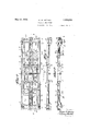
- My invention relates to railway rolling stock and consists in a novel underframe structure particularly adapted for use in locomotives'of the oil electric type which must carry heavyv internal combustion motors and a supply of fuel oil for the same.
- the main objects of my invention are to form a 'strong' light underframe structure adapted to carry motors of the class referred to and to provide fuel reservoirs therefor and to maintain a. low center of ⁇ gravity for-theV structure.
- Another object of my invention is to pro- Y vide a suitable support for the cab.
- Figure 2 is a. side view of the same.
- a Figure 3 is a vertical section taken on the longitudinal center line of the underframe.
- Figure 4 is an end view ofthe underframe.
- Figures 5, 6 and 7 are vertical transverse sections taken on the corresponding section lines of' Figure, 1. v
- Figure 8 is a. detail longitudinal section taken on the section lineS-S of Figure 1.
- Figure 9 is a horizontal section taken on the line 9 9 of Figure 3.
- Figure 10 is a detail of the reservoir wall which will be referred to later.
- Figure 11 is a. vertical transverse section on line 11-11 of Figure 1.
- sills .1 may an underframe
- These sills carry the majorvportion of the .ate the holsters and sills 1 and 2 on one side of the longitudinal center line of the locomotive have the lower portions of the deepened parts connected by a corrugated web '4: lformed integrally therewith.
- Transverse members 5 brace the longitudinal members 1 and 2 and form, with the latter, side walls of oil reservoirs or tanks Rlocated on each side o f the center of the frame.
- the underframe sills are provided with upper flanges 6 formmg top wall elements of the reservoirs andpreferably completed by means of plates P which are welded to the edges of flanges V6 to complete the reservoir top wall.
- a conduit betweenV reservoirs R provided by the elements 7 whereby the liquid in both reservoirs is maintained at the same level.
- the space be utilized as a reservoir, -the horizontal we s orbraces 8 being made continuous and .suitableopenings provided inthe sills 1 to permit liquid to pass between the reservoir outside of the sill 1 and the 'spaceinsideofthesillL' n,
- Themotor's will..be mounted on the bed preferablyby bein bolted tothe an'ges 6.
- I provide lugs 9 which form stops for engaging the ends of the motor frame. I show such a motor at M (see- Figure 6) with its base orlower crank case or voirs R.
- the frame also includes box shaped end ⁇ sills 10 and the 1 are extended downwardly at their ends to provide draft sills or housing forming-members 11 which, prefer# f ably, have the draft gear guiding elements 12 and stops 13 integral therewith.
- Plates v25 constitute platform-like extensions of the Vtop walls of sills 10 and the ends of plates 25 are recessed and depressed to provide steps 17.
- Side members 14 extend from platform to platform and are supported from sills l.2 by integral brackets 15.
- a suitable pad 16 extends all around the underfram'e on members 14 and plates 25 and is adapted to be finished to mountthe superstructure.
- Each of the holsters 3 comprises a top member 18 and vertical walls 19 and 2O which member andgwalls extend substantially from end to end of the bolster.
- a bottom member 23 extends between walls 19 and 2O and from theside bearing-24 on one side of the underframe to -the side bearing 24 on the other side of the underframe.
- This provides a bolster having a box shapebetween the side bearings and having an inverted U shape outwardly of the side earings.
- This construction permits a brake cylinder C, or other equipment mounted on the truck beneath the bolster, to project upwardly below the level of the bottomof the bolster and between walls 19 and 20.
- a railway vehicle underframe comprising longitudinal sills having portions arranged to support a motor positioned above said sills, and members between said sills forming therewith a closed liquidreservoir A below said portions.
- each pair of sills including portions arranged to carry a motor positioned above said sills, and members extending between each pair of sills and forming therewith a closed liquid reservoir between the center line of the locomotive and the side thereof and below said portions.
- each pair of sills including portions arranged to carry a motor positioned above -said sillsfmembers extending between each pair of sills and forming therewith a closed liquid reservoir between the center line of the locomotive and the side thereof and below said portions, and structure integral with said members and forming aconduit between said reservoirs.
- sills extending from end to end of t e underframe and havlng substantially deep-v ened central parts, the upper portions of said sills at said deepened parts forming a support for a motor positioned above said sills,
- spaced longitudinal sills including elements for mounting a motor superimposed thereon, outwardly extending brackets on the outer of said sills, longitudinal side members carried by said brackets, end sills, and a cab support element on said side members and end sills extending substantially continuously around said underframe.
- longitudinal and transverse webs on each sideV of the longitudinal center line of the frame including elements forming supports for motors carried on opposite sides of the underframe, and horizontal members spaced vertically of each other and connecting said webs and forming therewith liquid reservoir structures on each side of the under-frame below said elements, and a tie member extending from said structure on one side of the underframe to said structure on the other side of sald underframe, saidtie member being hollow to provide a liquid conduit between the interior of said reservoir structures.
- longitudinal sills deepened intermediate their ends and adapted to mount a motor on their deepened portions, and said depeened portions also forming liquid reservoir walls.
- a one piece casting comprising a railway locomotive underframe and including longitudinal sills provided with elements for supporting superimposed motors on each side of the longitudinal center line of the frame,
- a longitudinal sill and a bolster having a box shaped centerl portion and a substantially inverted U-shaped portion at the sidey of said center portion, saidU-shaped portion having its walls spaced apart so as to receive between them and to clear a brake cylinder mounted upon a truck beneath said bolster.
- a bolster including an inverted U-shape section arranged to extend over a truck, there being reinforcing flanges on the lower edges of the walls of said section, one of said flanges extending from the outer side of its wall to increase the distance between saidwalls to provide clearance for equipment mounted on v tudinally of the underframe, and center plate mounting ⁇ elements on said bolster located nearer to one of the side walls of said bolster than to the other side wall. 21.
- a bolster including upright walls spaced longi- 5 tudinally of the underframe, said bolster pro-A viding an air conduit and center plate mount- 'ing structure both nearer to one of the side walls of said bolster than to the other side wall.
- a center sill member In a railway vehicle, a center sill member, a longitudinal sill member spaced from w saidfcenter sill member, and a transverse bolster extending between said sill members with end portion corresponding indepth to the depth of said sill members and with its intermediate portion recessed upwardly above the level of the bottom of said sill members to clear equipment mounted on a truck beneath the bolster and between said sill memv 2o bers.
- an engine including a base 0r lower crank case member, an und-errame for supporting said engine member and provided with a"liquid reservoir located below said engine member and forming a part of said underframe.
- an engine including a crank case or base, an underframe including longitudinal sills for supporting said engine,
- transverse members connecting saidsills, said sills and members having. webs forming the sidewalls of a liquid compartment located below said engine.
- a bolster In a railway car underframe, a bolster, side bearing elements carried by said bolster, said bolster having a box section extending from one side bearing to the other and having an inverted U section outwardly of said Side bearings.
Landscapes
- Engineering & Computer Science (AREA)
- Mechanical Engineering (AREA)
- Body Structure For Vehicles (AREA)
Description
May 24, 1932. w. M. ssHEEl-IAN RAILWAY UNDERFRAME' 5 sheets-smet Filed Nov. lO, 1930 May 24, 1932- w. M. SHEEHAN` 1,859,938
RAILWAY UNDERFRAME Filed Nov. 10, 1930 3 Sheets-Sheet 2 Jig' 'j' J I 'ii g l x 4 I I r May 24, 1932- w. M. gHEEHAN 1,859,938
RAILWAY UNDER FRAME Filed Nov. 1o, 195o l 3 Sheets-sheer 3 Patented UNrrED STATES tassa PATENT oFFcE WILLIAM IML S, `0F MABON, PENNSYLVANIA, ASSIGNOR T0 GENERAL STEEL caemos CORPORATION, or GRANITE WARE- CITY,.1ILIN'0IS, A'GOBPOBATVION 0F Dm.-
RAJ'LWAY UNDERFBAME Application led November 10, 1930. Serial No. 494,781.
My invention relates to railway rolling stock and consists in a novel underframe structure particularly adapted for use in locomotives'of the oil electric type which must carry heavyv internal combustion motors and a supply of fuel oil for the same.
riveted'or bolted together to form j ints which The main objects of my invention are to form a 'strong' light underframe structure adapted to carry motors of the class referred to and to provide fuel reservoirs therefor and to maintain a. low center of `gravity for-theV structure.
It is/also an object of my invention toproduce the underframe in an integral structure, preferably madeof a`. single casting, whereby the-rigidity of the frame will be securedwithout the necessity .ef frequent inspection and repairs, such as is required for built-up structures having 'a number of parts work loose.' Incidentally, such joints require additionaljianges on the connected members,
the metal of which flanges is not used as effectively as in a cast structure where masses of metal need be used only where they con- Y tribute necessary strength to the structure.
Another object of my invention is to pro- Y vide a suitable support for the cab.
These and other detailed objects of my invention are attained by the structure shown in the acompanying drawings in which- Figure 1 is a top view o embodying my invention.
Figure 2 is a. side view of the same. A Figure 3 is a vertical section taken on the longitudinal center line of the underframe.
Figure 4 is an end view ofthe underframe.
Figures 5, 6 and 7 are vertical transverse sections taken on the corresponding section lines of'Figure, 1. v
Figure 8 is a. detail longitudinal section taken on the section lineS-S of Figure 1.
Figure 9 is a horizontal section taken on the line 9 9 of Figure 3.
Figure 10 is a detail of the reservoir wall which will be referred to later.
Figure 11 is a. vertical transverse section on line 11-11 of Figure 1.
AThe underframe in ludes four main longitudinal vertical .members or sills 1, 7 1, 2,2.
, between sills .1 may an underframe These sills carry the majorvportion of the .ate the holsters and sills 1 and 2 on one side of the longitudinal center line of the locomotive have the lower portions of the deepened parts connected by a corrugated web '4: lformed integrally therewith. Transverse members 5 brace the longitudinal members 1 and 2 and form, with the latter, side walls of oil reservoirs or tanks Rlocated on each side o f the center of the frame. The underframe sills are provided with upper flanges 6 formmg top wall elements of the reservoirs andpreferably completed by means of plates P which are welded to the edges of flanges V6 to complete the reservoir top wall. A conduit betweenV reservoirs R provided by the elements 7 whereby the liquid in both reservoirs is maintained at the same level. These elements 7 also fromasubstantial tie between the pairs of sills 1, 2 on opopsite sidesof the unlferframe.
greater capacity is desired, the space be utilized as a reservoir, -the horizontal we s orbraces 8 being made continuous and .suitableopenings provided inthe sills 1 to permit liquid to pass between the reservoir outside of the sill 1 and the 'spaceinsideofthesillL' n, Themotor's will..be mounted on the bed preferablyby bein bolted tothe an'ges 6. To' free the holdinggbolts from undue stresses resulting from the starting and Stopping of the locomotive, I provide lugs 9 which form stops for engaging the ends of the motor frame. I show such a motor at M (see-Figure 6) with its base orlower crank case or voirs R.
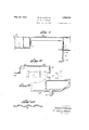
The frame also includes box shaped end `sills 10 and the 1 are extended downwardly at their ends to provide draft sills or housing forming-members 11 which, prefer# f ably, have the draft gear guiding elements 12 and stops 13 integral therewith. Plates v25 constitute platform-like extensions of the Vtop walls of sills 10 and the ends of plates 25 are recessed and depressed to provide steps 17.
Each of the holsters 3 comprises a top member 18 and vertical walls 19 and 2O which member andgwalls extend substantially from end to end of the bolster. A bottom member 23 extends between walls 19 and 2O and from theside bearing-24 on one side of the underframe to -the side bearing 24 on the other side of the underframe. This provides a bolster having a box shapebetween the side bearings and having an inverted U shape outwardly of the side earings. This construction permits a brake cylinder C, or other equipment mounted on the truck beneath the bolster, to project upwardly below the level of the bottomof the bolster and between walls 19 and 20. It is desirable to reinforce the bolster walls 19 and 20 with suitable flanges and these are indicated at 26 and 27 (see Figure 8) By turning flange 26 outwardly of the bolster side wall 20, I increase the clearance for the rear end of brake cylinder C so that it does not contact with the bolster wall 20 when the truck pivots on the unf.
derframe. By turning flange 27 inwardly of the bolster side wall 19, I increase the 'clearance for the upper end of the brake lever L towhich the brake rod B is connected. This construction facilitates the locationv of the bolster wall 19 as near as possible to the end of the'car, in view of the upstanding brakel lever L, the position of which is determined by the location of the truck which, of course, is pivoted to the underframe through the centerv plate structure 29 located as near the end of the car as is practical in view of the draft gear. A
As a result of constructing a bolster adapted to meet these conditions arising from the relative position of the truck center plate and desirable-that the bolster brace longitudinal sills 1 and 2 throughout their depth and therefore the portions of the bolster adjacent these sills should beas deep as these sills. Since these sills extend downwardly below the level of the top of the brake cylinder and associated parts, I have provided upwardly extending recesses in the lower parts of walls 19 and 20 as indicated at 28 in Figure 5.
The above description includes a number of details of construction which may be varied substantially, or omitted from the undery frame, without affecting other features of my invention and I refer particularly to the .extent and direction of the corrugations in websA, -to the offset relation of the center plate and bolster, and to thearrangement of the pads for supporting the ends of the superstructure. Obviously these features could be changed and I desire to include within the scope -of my invention all modifications of the construction which come within the scope of my claims.
I claim: Y
1. A railway vehicle underframe, comprising longitudinal sills having portions arranged to support a motor positioned above said sills, and members between said sills forming therewith a closed liquidreservoir A below said portions. v
2. In a railway vehicle underframe,.a pair of spaced sills on each side of the longitudinal center line of the underframe, each pair of sills including portions arranged to carry a motor positioned above said sills, and members extending between each pair of sills and forming therewith a closed liquid reservoir between the center line of the locomotive and the side thereof and below said portions.
3. In a railway vehicle underframe, a pair of spaced sills on each side of the longitudinal center line of the underframe, each pair of sills including portions arranged to carry a motor positioned above -said sillsfmembers extending between each pair of sills and forming therewith a closed liquid reservoir between the center line of the locomotive and the side thereof and below said portions, and structure integral with said members and forming aconduit between said reservoirs.
4. In a railway vehicle underframe, longitudinal sills extending from end to end of the underframe and having their intermediate portions deepened, a web connecting the upper portions of said sills and formingtherewith a support for a motor positioned above said sills, and a web connecting the lower portions of said sills, said webs and sillsforming a closed liquid reservoir below said motor.
5. In a railway vehicle underframe, lon tudinal sills extending from end to end of t e underframe and havlng substantially deep-v ened central parts, the upper portions of said sills at said deepened parts forming a support for a motor positioned above said sills,
anda web connecting the lower portions of said sills at said deepened parts and forming therewith the bottom and sides of a liquid reservoir below said motor.
6. -In a railway vehicle underframe, longitudinal sills constituting supports for a motor superimposed thereon, a web connecting the lower portions of said sills and forming aeeaeee a transverse brace between said sills and also forming the bottom of areservoir having said sills for side walls.
7. In a railway vehicle underframe, longitudinal sills'constituting supports for av motor superimposed thereon, a. web connecting the lower portions of said sills and form-v ing atransverse brace between said sllls and also forming the bottom of a reservoir having said sills for side walls, said web being corrugated throughout a substantial portion of its extent. Y
8. In a railway vehicle underfralne, longitudinal and transverse vertical webs having portions for supporting a motor to be superimposed thereon, and vertically spaced members connecting said webs and forming therewith a liquid reservoir having side, top and bottom walls below said portions.
9. In an underframe, spacedlongitudinal webs, spaced transverse webs, vertically spaced members connecting said webs and forming therewith a liquid reservoir having side, top and bottom walls, certain of said webs being adapted to support a motor to be superimposed thereon.
10. In a railway vehicle underframe, longitudinal sills adapted to mount a motor superimposed thereon, members `cooperating with said sills to form therewith a liquid reservoir beneath a motor mounted thereon, certain of said sills extending longitudinally of the underframe beyond said motor mounting and reservoir forming portion and constituting draft gear housing structures.
11. In a railway vehicle underframe, spaced longitudinal sills including elements for mounting a motor superimposed thereon, outwardly extending brackets on the outer of said sills, longitudinal side members carried by said brackets, end sills, and a cab support element on said side members and end sills extending substantially continuously around said underframe.
' 12. In a railway vehicle underframe, spaced longitudinal sills including elements for mounting a motor superimposed thereon,
-brackets integral with and extending outwardly from the outer sills, longitudinal side members integral with the outer ends of said brackets and extending substantially throughout the length of the underframe, end sills integral with and connecting the ends of said side members, and a cab support elementintegral with said side members and end sills and extending substantially continuously around the sides and ends of said underframe.
13. In a railway vehicle underframe,
longitudinal and transverse webs on each sideV of the longitudinal center line of the frame including elements forming supports for motors carried on opposite sides of the underframe, and horizontal members spaced vertically of each other and connecting said webs and forming therewith liquid reservoir structures on each side of the under-frame below said elements, and a tie member extending from said structure on one side of the underframe to said structure on the other side of sald underframe, saidtie member being hollow to provide a liquid conduit between the interior of said reservoir structures.
14. In a railway vehicle underframe, longitudinal sills deepened intermediate their ends and adapted to mount a motor on their deepened portions, and said depeened portions also forming liquid reservoir walls.
15. In an url derframe of the class described, horizontal elements for mounting a separately formed motor carried on the underframe, and upstanding members integral with said elements and forming stops for engaging a motor to hold the same against longitudinal movement.y
16. A one piece casting comprising a railway locomotive underframe and including longitudinal sills provided with elements for supporting superimposed motors on each side of the longitudinal center line of the frame,
and side members spaced from said elements, and end members connecting said sills and side members, there being a continuous pad on said side members and end members extending substantially entirely around the underframe for mounting a cab structure.
17. In a railway vehicle underframe, longitudinal centersills, and -a bolster, side bearings on-said bolster spaced from said center sills, said bolster having a box shaped center portion extendin-g between said sid-e bearings, and substantially inverted U-shaped portions at the sides of said center portion.
18. In a railway vehicle underframe, a longitudinal sill and a bolster having a box shaped centerl portion and a substantially inverted U-shaped portion at the sidey of said center portion, saidU-shaped portion having its walls spaced apart so as to receive between them and to clear a brake cylinder mounted upon a truck beneath said bolster. v
19. In a railway vehicle underframe, a bolster including an inverted U-shape section arranged to extend over a truck, there being reinforcing flanges on the lower edges of the walls of said section, one of said flanges extending from the outer side of its wall to increase the distance between saidwalls to provide clearance for equipment mounted on v tudinally of the underframe, and center plate mounting` elements on said bolster located nearer to one of the side walls of said bolster than to the other side wall. 21. In a railway vehicle underframe, a bolster including upright walls spaced longi- 5 tudinally of the underframe, said bolster pro-A viding an air conduit and center plate mount- 'ing structure both nearer to one of the side walls of said bolster than to the other side wall.
22. In a railway vehicle, a center sill member, a longitudinal sill member spaced from w saidfcenter sill member, and a transverse bolster extending between said sill members with end portion corresponding indepth to the depth of said sill members and with its intermediate portion recessed upwardly above the level of the bottom of said sill members to clear equipment mounted on a truck beneath the bolster and between said sill memv 2o bers.
23. In a locomotive, an engine including a base 0r lower crank case member, an und-errame for supporting said engine member and provided with a"liquid reservoir located below said engine member and forming a part of said underframe. x
24. In a locomotive, an engine including a crank case or base, an underframe including longitudinal sills for supporting said engine,
transverse members connecting saidsills, said sills and members having. webs forming the sidewalls of a liquid compartment located below said engine. 25. In a railway car underframe, a bolster, side bearing elements carried by said bolster, said bolster having a box section extending from one side bearing to the other and having an inverted U section outwardly of said Side bearings. In testimony whereof I hereunto aiix my signature this 30th day of October, 1930.. WILLIAM M. SHEEHAN.
Priority Applications (1)
| Application Number | Priority Date | Filing Date | Title |
|---|---|---|---|
| US494781A US1859938A (en) | 1930-11-10 | 1930-11-10 | Railway underframe |
Applications Claiming Priority (1)
| Application Number | Priority Date | Filing Date | Title |
|---|---|---|---|
| US494781A US1859938A (en) | 1930-11-10 | 1930-11-10 | Railway underframe |
Publications (1)
| Publication Number | Publication Date |
|---|---|
| US1859938A true US1859938A (en) | 1932-05-24 |
Family
ID=23965939
Family Applications (1)
| Application Number | Title | Priority Date | Filing Date |
|---|---|---|---|
| US494781A Expired - Lifetime US1859938A (en) | 1930-11-10 | 1930-11-10 | Railway underframe |
Country Status (1)
| Country | Link |
|---|---|
| US (1) | US1859938A (en) |
-
1930
- 1930-11-10 US US494781A patent/US1859938A/en not_active Expired - Lifetime
Similar Documents
| Publication | Publication Date | Title |
|---|---|---|
| US1696332A (en) | Underframe for well cars | |
| US1859938A (en) | Railway underframe | |
| US1835673A (en) | Cab underframe | |
| US1801938A (en) | Oil-electric-locomotive platform | |
| US1663036A (en) | Railway vehicle structure | |
| US1948250A (en) | Railway truck | |
| US2056228A (en) | Rail car | |
| US1769490A (en) | grossman | |
| US1842423A (en) | Railway car | |
| US2110019A (en) | Railway vehicle structure | |
| US1729434A (en) | Engine truck | |
| US2098516A (en) | Railway car construction | |
| US1985380A (en) | Hopper car | |
| US1891954A (en) | Cab underframe | |
| US1683672A (en) | Locomotive structure | |
| US1865520A (en) | Railway vehicle structure | |
| US1833094A (en) | Locomotive frame | |
| US894342A (en) | Car-truck. | |
| US1825476A (en) | Railway car structure | |
| US2259477A (en) | Railway truck | |
| US1859895A (en) | Railway vehicle underframe | |
| US2185975A (en) | Tractor unit | |
| US1378204A (en) | Locomotive-tender underframe | |
| US1047442A (en) | Locomotive-tender underframe. | |
| US1765465A (en) | Combined body-bolster and draft-sill casting |