US1859909A - Reversing gear mechanism - Google Patents
Reversing gear mechanism Download PDFInfo
- Publication number
- US1859909A US1859909A US400504A US40050420A US1859909A US 1859909 A US1859909 A US 1859909A US 400504 A US400504 A US 400504A US 40050420 A US40050420 A US 40050420A US 1859909 A US1859909 A US 1859909A
- Authority
- US
- United States
- Prior art keywords
- casing
- gear
- shaft
- gearing
- gear mechanism
- Prior art date
- Legal status (The legal status is an assumption and is not a legal conclusion. Google has not performed a legal analysis and makes no representation as to the accuracy of the status listed.)
- Expired - Lifetime
Links
- 230000003137 locomotive effect Effects 0.000 description 7
- 230000002427 irreversible effect Effects 0.000 description 6
- 238000010276 construction Methods 0.000 description 4
- 241000271569 Rhea Species 0.000 description 1
- 208000027418 Wounds and injury Diseases 0.000 description 1
- 230000006978 adaptation Effects 0.000 description 1
- 229940000425 combination drug Drugs 0.000 description 1
- 230000006378 damage Effects 0.000 description 1
- 239000000428 dust Substances 0.000 description 1
- 239000012530 fluid Substances 0.000 description 1
- 208000014674 injury Diseases 0.000 description 1
- 238000007689 inspection Methods 0.000 description 1
- 239000000314 lubricant Substances 0.000 description 1
- 230000003340 mental effect Effects 0.000 description 1
- 108090000623 proteins and genes Proteins 0.000 description 1
- 238000000926 separation method Methods 0.000 description 1
- 238000007873 sieving Methods 0.000 description 1
Images
Classifications
-
- F—MECHANICAL ENGINEERING; LIGHTING; HEATING; WEAPONS; BLASTING
- F01—MACHINES OR ENGINES IN GENERAL; ENGINE PLANTS IN GENERAL; STEAM ENGINES
- F01L—CYCLICALLY OPERATING VALVES FOR MACHINES OR ENGINES
- F01L29/00—Reversing-gear
- F01L29/04—Reversing-gear by links or guide rods
-
- Y—GENERAL TAGGING OF NEW TECHNOLOGICAL DEVELOPMENTS; GENERAL TAGGING OF CROSS-SECTIONAL TECHNOLOGIES SPANNING OVER SEVERAL SECTIONS OF THE IPC; TECHNICAL SUBJECTS COVERED BY FORMER USPC CROSS-REFERENCE ART COLLECTIONS [XRACs] AND DIGESTS
- Y10—TECHNICAL SUBJECTS COVERED BY FORMER USPC
- Y10T—TECHNICAL SUBJECTS COVERED BY FORMER US CLASSIFICATION
- Y10T74/00—Machine element or mechanism
- Y10T74/18—Mechanical movements
- Y10T74/18568—Reciprocating or oscillating to or from alternating rotary
- Y10T74/18576—Reciprocating or oscillating to or from alternating rotary including screw and nut
Definitions
- ooMPANY or oinoAeo, ILLINOIS
- the rincipal objects ofthe present invention are the provision of. an i proved form reversing.
- Step bushings 27, 27 are provided-at eefch end of the spiral gear slndare provided;;with step-hearings; 28, which seryenot'f only-to support the rod 15 but also as abutment mem 'bers for the gear 22 and retainers for the hub-caps 26.
- the hollow center of the caslng'structure, 10, above described, is provided with suitcellar for the several gearing elements.
- V V v For enclosing and protecting the projecting portions of the rod 15, there is detachably applied at each .end of the casing, '10, housings, 15a, 155, which further serve. to prevent the ingress of extraneous matter such as dirt or moisture into the casing 10.
- Suchrod, 15, is non-circular, and is,supported in the casing for through.
- the spiral worm'18" engages a segmental rack 21 carried on the tumbling shaft, 9,
- the casing 10 is made in two parts, 10"
- the casing, 10 is provided at one end with the integral housing extension,15c, and at the'other end with the housing 150? detachably mounted thereable cap pieces, 29, 30, forming a lubricant u 011'.
- the worm and segment structures 18, 19, and 18, 19, above described provide an irreversible I connection for operating the valve gear mechandholding the gearing in predetermined relation to the caslng, and a-member mov able through said casingfor actuating said gearing, said member extending beyond the casing, and'a housing structure on the casing forenclosing the projecting portion of said actuating member,- both the closing meinbers andthe housing structure being attached to the casing by meansreadil'y removablefrom the exterior ofthe casing, whereby the gearing and actuating member may be readily dlsassembled from position in the casing 2.
- a gearing casing in com bination, a gearing casing,a revoluble element in said casing, a member movable through said casing for imparting rotary movement to said revoluble element,an' end bearing in said casing in which said movable member moves and by which said revoluble c element is held against endwise movement in one direction, said movable-member projecting beyond both ends of said;v casing, means for readily removably retaining said bearing, and a housing at each end of the casing and extending therefrom to enclose those portions of the movable memberextending beyond the casing.
- a motion transmitting mechanism forming a unitary structurefadapted to be attachedto a power operated mechanism and to receive a part of the tumbling shaft of a locomotive reversing gear mechanism which includes, in combination, a casing provided with a chamber cont-jainingbearings' forthe tumbling shaft, a segmental gear receivable in said casing for attachment to said shaft, a revoluble element mounted in a portion'of said casing adjacent to saidchamber. and operatively engaging with said segmental gear to form.
- an end bearing in said casing for preventing endwise movement of said revoluble element but, upon removal of said bearing, permitting the ready removal of said revoluble element without disturbing said segmental gear, and a motion transmitting element extending "through said'revoluble element for impartl ing motion thereto, said motion imparting element being mounted in said end bearing.
- a bodily removable unit mechanism for operating locomotive reverse gears and the like, in combination with the shaft to be moved, a casing having separable parts adapted to embrace said shaft and form spaced bearings therefor, a segmental gear in said casing adapted to be affixed to the portion of said shaft between said bearings, a worm in saldcaslng for driving-sald seg-' mental gear disposed on an axis at an angle thereto to form an irreversible connection,
- casing having separable parts forming bear ings for and embracing and supporting said tumbling shaft, a driven gear element injs'aid casing and fixed to saidtumbling shaft, a
Landscapes
- Engineering & Computer Science (AREA)
- Mechanical Engineering (AREA)
- General Engineering & Computer Science (AREA)
- Multiple-Way Valves (AREA)
- Gear Transmission (AREA)
Description
May 24, 1932. c. c. BERTRAM REVERSING GEAR MECHANISM Original Filed July 31, 1920 2 Sheets-She et l w i 2Q May 24, 1932. UBE TRA 1,859,909
REVERSI NC- GEAR MECHANISM ori inai'wiled July 51, 1920 2 Sheets-Sheet 2 Tilt Patented Mey 24, 1932 UNITED enmnnon d. Bm rmor CHICAGO, ltmnois, Assidifdfi 66 134x366 mti'mrhbremn;
ooMPANY, or oinoAeo, ILLINOIS, A eomomrmn ofvliiiilfixfois" EA'n 'iiipl'ictioii rhea my 31, 1920, stem special reference to" the provision of an imk iev'ed arran ement-0f irreversible driving mechanism therefor; i 7 The rincipal objects ofthe present invention are the provision of. an i proved form reversing. gear mechanism and more specific'ally 'o'fie-adtpted for rea dy iiistztllation in existing structures; the rovision of sin impreved g'ttiihgiahd more particularly, irreversible gearing-for establishing a driving connection between a suitably driven eleinn-1t 51nd the mechanism to be moved there by the provisi n of an improved valve-gear sieving reversin mecha ism adapted for tpplizmtiofi' to the present-arrangement of tninbling shaft and associated parts; the provision in general'of improved arrangein'nt of motion Converting and transmitting "elements; and one es ecially adapted for controlling th-fiil e nieohanism ofstea-m engines' 1 together with such further and additram oh je'ets-as may-be below set forth.
' Mechanism of the ChitfztCter referred to htiie gene a field of usefulness-a d are (if satirical-er utility the operation of the valve mechanism of large steam engines;
1 Fer tile-persons of illustration;therefore, the inventions hfi e been snows strnctilrally ihh'did iii forfii 'ida'p'ted for eipplioationto --th trimmin shift df railway locomotive {engineifi shell, a manner as to function as getting for opening and Closing, and formwa in the valve ifiec'lianis'nr thereof.
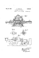
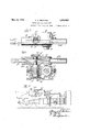
' "In th seedfnpafiyifigl dmwi gs, therei fl f li i g'gil're', I- is' an eleiisltionagl View illiis't'ratiye of p'alft of the oyliilder'aiid assoieted driving nichanism and valve-gear operating meohanism of a railway locomotive, haying a strnctui'e embodying thepresent invention suitably arranged and included therein; Figure 2 is a longitudinal seotionail elevational iew, on a n enlarged sale, of part of thq structn feof Figiirelj J L 1 m Figure 3 is a sectional viewof a detail of $166564; R'iiib'ed dioisems, 1921'.
construction, taken 01; theline ure2;'- V. Figure 4 is'ain elevational viewfiof another detailjdf construction; v Fi "res- 5 and 6 are views similar to't'hose of Figures" 1 and 2 illustrative of another em- 'bodim'efnt ofthe invention,-ancl t 1 Fi um-'7 a top' plan View of the structure illustrated in vertical seotioh in Fig 111156."
Referring era'tively connected to-the rezrch rod=,=5'l-, "by
first to Figure 1170f the drat v vings thereihas-been ln'dicated generally adjacent.
eseht Referrin now 'to'Figure- '2 or the clrawings; there is provided a 'osisingl struture 10,:
5 Within which is nionnted the. gearing for op erttin'g the tuinhling shaft, 9.; "This gear'ing 7 includes. primarily "an actuating: rbd 15 reclprocated in a'riydesiredmanner, (prefer ably however frome power oylinderfP at a distant point) Suich rod 15 has a doiihle spiral groove 16; 17, yvith which engage pro jections 18,19 on ai -sle've' 20. Asia result of this symmetrical arrangement a; balzliioed "operative construction is attaindand "shearingof the: prfojection's ls and '19 is rendered To the sleevefl2'0' secured; prefer unlikely. I I ably the key 21, a spiral WrrhyZZ, en ag ing atoothed seg'rhnt x23, fast on thetuin- :blingliztft; 9; rotatable in beerings 9aii1the casing 10.
The two sleeves; 20; 2mm prerrfabi ee terminous' 'ah'd sti'e onveniently olose'dfiet their ends by retain1n menihrs'26'; 26;vvl1ieh L serve dust cfipsw It Will-he apparent that,
by providing the twosepatrahle nested sleeves- 20, 22, injury to orwear of'eithelro f the sleevesywill not require disczirdingl Lofboth,
The hollow center of the caslng'structure, 10, above described, is provided with suitcellar for the several gearing elements.
It will readily be appreciated that the sev- V eral parts, to-wit': the bushings, 27, 27, bearings, 28, 28 and 'end caps, 29,30, together form removable closures to enable the disassembly of the gearing mechanism from the casing. To permit of such disassembling operation being readily performed, the means securing these several parts to the casing, 10,
"are all easily reached fromthe exterior of the casing 10. V V v For enclosing and protecting the projecting portions of the rod 15, there is detachably applied at each .end of the casing, '10, housings, 15a, 155, which further serve. to prevent the ingress of extraneous matter such as dirt or moisture into the casing 10.
Referring now'more particularly to Figures to 7 of the drawings wherein there is illustrated another embodiment of the. invention, it will'be observed that there is here again illustrated an adaptation of the invention to the Baker-Pilliod type of valve gear for controlling the admission of fluid to the locomotive cylinders,indicated generally at A. This is connected'as before to the tumbling shaft 9 by. the socalled sh'ortreach Turning now to Figure 6 of the drawings, there is shown a casing 10 w1th1n which 'mounted the gearing for operating the tumbling shaft 9. This gearing includes pri marilyan actuating rod'15 reciprocated in any. desired manner, as before suggested.
Suchrod, 15,is non-circular, and is,supported in the casing for through. I j
reciprocation thereing 10 and against longitudinal movement by means of'the bushings 20", one of and 10".
which is disposed in the removable cap member 11 and the other in the casing '10', and
thereduced outer end-of the gear-member 18 V is disposed in a bushing 20 carried'ina re-' c movable cap member 11".
The spiral worm'18" engages a segmental rack 21 carried on the tumbling shaft, 9,
in the casing 10.
' The casing 10 is made in two parts, 10"
These parts are detachably attached for ready separation in .any' conveni- \ent manner.
It will beobvious upon'inspection of Figure 6 of the drawings that this construction permits the removal of various elements contained in the casing 10" with facility.
For enclosing and protecting the projecting portions'of the rod, 15, the casing, 10, is provided at one end with the integral housing extension,15c, and at the'other end with the housing 150? detachably mounted thereable cap pieces, 29, 30, forming a lubricant u 011'. I i It willbe understood, of course, that the worm and segment structures 18, 19, and 18, 19, above described, provide an irreversible I connection for operating the valve gear mechandholding the gearing in predetermined relation to the caslng, and a-member mov able through said casingfor actuating said gearing, said member extending beyond the casing, and'a housing structure on the casing forenclosing the projecting portion of said actuating member,- both the closing meinbers andthe housing structure being attached to the casing by meansreadil'y removablefrom the exterior ofthe casing, whereby the gearing and actuating member may be readily dlsassembled from position in the casing 2. In a reversing gear mechanism, in com bination, a gearing casing,a revoluble element in said casing, a member movable through said casing for imparting rotary movement to said revoluble element,an' end bearing in said casing in which said movable member moves and by which said revoluble c element is held against endwise movement in one direction, said movable-member projecting beyond both ends of said;v casing, means for readily removably retaining said bearing, and a housing at each end of the casing and extending therefrom to enclose those portions of the movable memberextending beyond the casing. i
3. In a motion transmitting mechanism forming a unitary structurefadapted to be attachedto a power operated mechanism and to receive a part of the tumbling shaft of a locomotive reversing gear mechanism which includes, in combination, a casing provided with a chamber cont-jainingbearings' forthe tumbling shaft, a segmental gear receivable in said casing for attachment to said shaft, a revoluble element mounted in a portion'of said casing adjacent to saidchamber. and operatively engaging with said segmental gear to form. an irreversible connection, an end bearing in said casing for preventing endwise movement of said revoluble element but, upon removal of said bearing, permitting the ready removal of said revoluble element without disturbing said segmental gear, and a motion transmitting element extending "through said'revoluble element for impartl ing motion thereto, said motion imparting element being mounted in said end bearing.
4. In a bodily removable unit mechanism for operating locomotive reverse gears and the like, in combination with the shaft to be moved, a casing having separable parts adapted to embrace said shaft and form spaced bearings therefor, a segmental gear in said casing adapted to be affixed to the portion of said shaft between said bearings, a worm in saldcaslng for driving-sald seg-' mental gear disposed on an axis at an angle thereto to form an irreversible connection,
bearings in said casing for said worm readilyremovable to permit of removal ofthe worm, and a reciprocating member extend' mg from said casing and mounted in bear 7 ings in said casing and operatively connected to impart movement to said worm, removal of one of sald worm bearings permltting removal ofthe worm and said reciprocating member. v
5. In a valve gear reversing mechanism for locomotives, in combination with the tumbling shaft of a locomotive valve gear, a
casing having separable parts forming bear ings for and embracing and supporting said tumbling shaft, a driven gear element injs'aid casing and fixed to saidtumbling shaft, a
' motion imparting meansalso in said casing including relatively operably connected e1ements one of which is reciprocable and pro jec'ts from the casing and is angularly related to and forms an irreversible connection with said driven gear, and removable bearings in CLARENCE o. BERTRAML' s an.
Priority Applications (1)
| Application Number | Priority Date | Filing Date | Title |
|---|---|---|---|
| US400504A US1859909A (en) | 1920-07-31 | 1920-07-31 | Reversing gear mechanism |
Applications Claiming Priority (1)
| Application Number | Priority Date | Filing Date | Title |
|---|---|---|---|
| US400504A US1859909A (en) | 1920-07-31 | 1920-07-31 | Reversing gear mechanism |
Publications (1)
| Publication Number | Publication Date |
|---|---|
| US1859909A true US1859909A (en) | 1932-05-24 |
Family
ID=23583878
Family Applications (1)
| Application Number | Title | Priority Date | Filing Date |
|---|---|---|---|
| US400504A Expired - Lifetime US1859909A (en) | 1920-07-31 | 1920-07-31 | Reversing gear mechanism |
Country Status (1)
| Country | Link |
|---|---|
| US (1) | US1859909A (en) |
Cited By (3)
| Publication number | Priority date | Publication date | Assignee | Title |
|---|---|---|---|---|
| US2441199A (en) * | 1944-03-06 | 1948-05-11 | Franklin Railway Supply Co | Rotary cam mechanism for actuating the valves of locomotives |
| US20150135867A1 (en) * | 2013-11-15 | 2015-05-21 | Taiger International Corp. | Swing type power door lock motor |
| US10435923B2 (en) | 2013-11-15 | 2019-10-08 | Taiger International Corp. | Swing type power door lock actuator |
-
1920
- 1920-07-31 US US400504A patent/US1859909A/en not_active Expired - Lifetime
Cited By (3)
| Publication number | Priority date | Publication date | Assignee | Title |
|---|---|---|---|---|
| US2441199A (en) * | 1944-03-06 | 1948-05-11 | Franklin Railway Supply Co | Rotary cam mechanism for actuating the valves of locomotives |
| US20150135867A1 (en) * | 2013-11-15 | 2015-05-21 | Taiger International Corp. | Swing type power door lock motor |
| US10435923B2 (en) | 2013-11-15 | 2019-10-08 | Taiger International Corp. | Swing type power door lock actuator |
Similar Documents
| Publication | Publication Date | Title |
|---|---|---|
| US1349660A (en) | Connection between piston-rods and crank-shafts | |
| US1859909A (en) | Reversing gear mechanism | |
| US1891545A (en) | Reverse gear mechanism | |
| US465100A (en) | Steam engine | |
| US779328A (en) | Mechanical movement for gas-engines. | |
| US1856246A (en) | Sleeve valve actuating mechanism | |
| US3299720A (en) | Piston pump with transverse thread actuator | |
| US749958A (en) | Steam-engine | |
| US1888448A (en) | Crank mechanism for reciprocating engines | |
| US2032952A (en) | Engine | |
| US2163929A (en) | Control of the sleeve valves of engines | |
| SU50232A1 (en) | Mechanism for transferring motion to the working shaft from the cylinder in a piston pulling machine | |
| US968445A (en) | Mechanical movement. | |
| US1346617A (en) | Valve mechanism | |
| US725945A (en) | Steam-engine. | |
| US807896A (en) | Switch-operating mechanism. | |
| US1965406A (en) | Means for stabilizing reverse gears | |
| US797555A (en) | Internal-combustion engine. | |
| US771095A (en) | Gas-engine. | |
| US1786260A (en) | Switch stand | |
| US722742A (en) | Rotary engine. | |
| US992424A (en) | Multicylinder oscillating steam-engine. | |
| US1013549A (en) | Valve-gear. | |
| US979002A (en) | Valve-gear. | |
| US1050528A (en) | Fluid-pressure motor. |