US1858045A - Wire support - Google Patents
Wire support Download PDFInfo
- Publication number
- US1858045A US1858045A US284988A US28498828A US1858045A US 1858045 A US1858045 A US 1858045A US 284988 A US284988 A US 284988A US 28498828 A US28498828 A US 28498828A US 1858045 A US1858045 A US 1858045A
- Authority
- US
- United States
- Prior art keywords
- insulator
- sections
- conductors
- bracket
- support
- Prior art date
- Legal status (The legal status is an assumption and is not a legal conclusion. Google has not performed a legal analysis and makes no representation as to the accuracy of the status listed.)
- Expired - Lifetime
Links
- 239000012212 insulator Substances 0.000 description 26
- 239000004020 conductor Substances 0.000 description 15
- 239000002184 metal Substances 0.000 description 6
- XLYOFNOQVPJJNP-UHFFFAOYSA-N water Substances O XLYOFNOQVPJJNP-UHFFFAOYSA-N 0.000 description 2
- 230000000295 complement effect Effects 0.000 description 1
- 238000010276 construction Methods 0.000 description 1
- 230000037431 insertion Effects 0.000 description 1
- 238000003780 insertion Methods 0.000 description 1
- 239000000463 material Substances 0.000 description 1
Images
Classifications
-
- F—MECHANICAL ENGINEERING; LIGHTING; HEATING; WEAPONS; BLASTING
- F16—ENGINEERING ELEMENTS AND UNITS; GENERAL MEASURES FOR PRODUCING AND MAINTAINING EFFECTIVE FUNCTIONING OF MACHINES OR INSTALLATIONS; THERMAL INSULATION IN GENERAL
- F16L—PIPES; JOINTS OR FITTINGS FOR PIPES; SUPPORTS FOR PIPES, CABLES OR PROTECTIVE TUBING; MEANS FOR THERMAL INSULATION IN GENERAL
- F16L3/00—Supports for pipes, cables or protective tubing, e.g. hangers, holders, clamps, cleats, clips, brackets
- F16L3/22—Supports for pipes, cables or protective tubing, e.g. hangers, holders, clamps, cleats, clips, brackets specially adapted for supporting a number of parallel pipes at intervals
- F16L3/23—Supports for pipes, cables or protective tubing, e.g. hangers, holders, clamps, cleats, clips, brackets specially adapted for supporting a number of parallel pipes at intervals for a bundle of pipes or a plurality of pipes placed side by side in contact with each other
-
- F—MECHANICAL ENGINEERING; LIGHTING; HEATING; WEAPONS; BLASTING
- F16—ENGINEERING ELEMENTS AND UNITS; GENERAL MEASURES FOR PRODUCING AND MAINTAINING EFFECTIVE FUNCTIONING OF MACHINES OR INSTALLATIONS; THERMAL INSULATION IN GENERAL
- F16L—PIPES; JOINTS OR FITTINGS FOR PIPES; SUPPORTS FOR PIPES, CABLES OR PROTECTIVE TUBING; MEANS FOR THERMAL INSULATION IN GENERAL
- F16L3/00—Supports for pipes, cables or protective tubing, e.g. hangers, holders, clamps, cleats, clips, brackets
- F16L3/08—Supports for pipes, cables or protective tubing, e.g. hangers, holders, clamps, cleats, clips, brackets substantially surrounding the pipe, cable or protective tubing
- F16L3/10—Supports for pipes, cables or protective tubing, e.g. hangers, holders, clamps, cleats, clips, brackets substantially surrounding the pipe, cable or protective tubing divided, i.e. with two members engaging the pipe, cable or protective tubing
Definitions
- invention relates particularly to means for carryingconductor wires known inthe art as duplexstreet lighting cable down ,polesand the .likeiand has asranobject-to provide .a support of the character described in which the insulator is .so shaped that rain and snow will be directed towards the in sulated conductors and away from the metal .parts of .the supporting bracket to pass through the aperture in which they are plositione'd and then downwardly along the conductors.
- Another object of this invention resides in the provision of a support in which the creepage distance between the metal parts thereof and the conductor Wires is relatively increased.
- Another object of this invention resides in the provision of a support of the character described in which the parts are so constructed as to obviate the necessity of taking the bracket apart to insert the conductors in position.
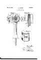
- Figure 2 is a sectional view taken through Figure 1 on the plane of the line 2-2, and
- Figure '3 is a perspective view of one of the insulator .sections.
- 5 represents .a bracket arm having a screw 6 by which the bracket may be attached :to .a pole .or other support and having 12111 arm 7 substantially arcuate in shape extended laterally from .its other end.
- the end of the bracket .5 adjacent the arm 17 is provided with a substantially V shaped trough or groove .8 which is adapted to engage-a correspondingly shaped portion 9 of: one oiftwo similar sections 10 of an insulator.
- Each section 10 :of the insulator has its medial port-ion channeled, ,as at 11, .so that when :the sections are arranged with their flat faces engaged, .as in Figure 1, the channeled portions .11 form .an elongated ,open
- the arm Thas its outer portion a'pertured as at 13 to .receivea clamping screw 14 which passes through .an aperture 15 in .a clamping member 16 the outer .end of which is provided with :a V shaped groove or trough l7 similar .to the trough 8 in the bracket 5.to engage the faces :of the portion .9 of the othersection of the insulator.
- the sections forming the insulator have their ends dished inwardly, as at 22, vfrom their outer periphery towards the elongated opening formed by the adjacent channels 11 so that when the insulator is :mounted in position.
- water from heavy rains and snows is directed inwardly towards the aperture and the conductors away from the metal parts of the support to follow downwardly along the insulated conductors and thus preyentthe possibility of a short should a con- Ion stant stream of water extend from the conductors towards the metal parts of the support.
- the dished portion 22 at the lowermost end of the insulator acts as a petticoat to maintain the same substantially dry at all times.
- the portions 9 of the insulator sections are substantially V shaped in cross section to correspond with the angle of the troughs 8 and 17 and have their apexes flattened, as at 23, and form the bottom of a groove 24 which extends throughout the major portion of the periphery of each section and is of a width slightly greater than the width of the portions 8 and 17 to maintain the sections of the insulator in proper longitudinal alignment.
- the insertion of the conductors 12 in the elongated aperture of the insulator is accomplished without the necessity of disassembling the parts, by merely loosening the clamping screw to a degree sufiicient to permit the insulator sections to be separated sufliciently to receive the conductors which are passed between their adjacent faces into the elongated opening.
- bracket or the clamping member engages the insulator at or near the split between its two sections so that the creepage distance between the conductor and the metal parts is not lowered by the existence of the split.
- a device of the character described comprising an insulator having an axial conductor receiving opening and split diametrically to divide the same into complementary sections, a bracket having a part engaged with a fiat walled recess formed in one section at its outer central portion so as to be spaced considerably from the extremities of the split between the insulator sections, a clamping member having a part engaged with a flat walled recess formed in the outer central portion of the other insulator section, whereby said part of the clamping member is likewise spaced considerably from the extremities of the split between the insulator sections, and means spaced from the insulator for drawing the clamping member to
Landscapes
- Engineering & Computer Science (AREA)
- General Engineering & Computer Science (AREA)
- Mechanical Engineering (AREA)
- Insulators (AREA)
Description
May 10, 1932. L. E. HENDEE WIRE SUPPORT Filed June 15, 1928 Patented May 10, 1932 UNITED STATES PATENT QFFICE LEM 'E. HENDEE, OF MILWAUKEE, WISCONSIN, ASSIGNOR, 'lBY'MESNE ASSIGN MENTS, TO .LINE'MATERIAL 'COMPAN Y, OF SOUTH IVIILW AUK'EE, WISCONSIN, A CORPORATIONQF .DELAWARE WIRE SUP-PORT Application :filed June .13,
invention relates particularly to means for carryingconductor wires known inthe art as duplexstreet lighting cable down ,polesand the .likeiand has asranobject-to provide .a support of the character described in which the insulator is .so shaped that rain and snow will be directed towards the in sulated conductors and away from the metal .parts of .the supporting bracket to pass through the aperture in which they are plositione'd and then downwardly along the conductors.
Another object of this invention resides in the provision of a support in which the creepage distance between the metal parts thereof and the conductor Wires is relatively increased.
Another object of this invention resides in the provision of a support of the character described in which the parts are so constructed as to obviate the necessity of taking the bracket apart to insert the conductors in position.
And a further object of this invention re sides in the provision of a support of the character described in which a single screw maintains the parts in their proper assembled position.
With the above and other objects in view which will appear as the description proceeds, my invention resides in the novel construction, combination and arrangement of parts substantially as hereinafter described and more particularly defined by the appended claims, it being understood that such changes in the precise embodiment of the hereindisclosed invention may be made as come within the scope of the claims.
In the accompanying drawings, I have illustrated one complete example of the physical embodiment of my invention constructed according to the best mode I have so far devised for the practical application of the principles thereof, and in which:
Figure 1 is a top plan View of the support embodying my invention, a portion of the insulator being broken away and shown in section;
Figure 2 is a sectional view taken through Figure 1 on the plane of the line 2-2, and
1928. Serial No. 284,988.
Figure '3 is a perspective view of one of the insulator .sections.
Referring .now more particularly .to the accompanying :drawings in which like :nu-
,merals designate like parts throughout :the
several views, 5 represents .a bracket arm having a screw 6 by which the bracket may be attached :to .a pole .or other support and having 12111 arm 7 substantially arcuate in shape extended laterally from .its other end. The end of the bracket .5 adjacent the arm 17 is provided with a substantially V shaped trough or groove .8 which is adapted to engage-a correspondingly shaped portion 9 of: one oiftwo similar sections 10 of an insulator. Each section 10 :of the insulator has its medial port-ion channeled, ,as at 11, .so that when :the sections are arranged with their flat faces engaged, .as in Figure 1, the channeled portions .11 form .an elongated ,open
.ing in which conductors 12 are received.
The arm Thas its outer portion a'pertured as at 13 to .receivea clamping screw 14 which passes through .an aperture 15 in .a clamping member 16 the outer .end of which is provided with :a V shaped groove or trough l7 similar .to the trough 8 in the bracket 5.to engage the faces :of the portion .9 of the othersection of the insulator. A lug lS-eXtended trom the end of the member 16 adjacent the clamping screw engages the edge 19 of .the adjacent end of the arm 7 to properly align the member 16 with the bracket and .a projection or step .20 formed adjacent thereto engages theouter face 2-1 of sthe armato form substantially a fulcrum about which the clamping member 16 :pivots as the screw 14 is drawn tight to secure the sections of the insulator in their .proper position.
The sections forming the insulator have their ends dished inwardly, as at 22, vfrom their outer periphery towards the elongated opening formed by the adjacent channels 11 so that when the insulator is :mounted in position. water from heavy rains and snows is directed inwardly towards the aperture and the conductors away from the metal parts of the support to follow downwardly along the insulated conductors and thus preyentthe possibility of a short should a con- Ion stant stream of water extend from the conductors towards the metal parts of the support. It will be noted that the dished portion 22 at the lowermost end of the insulator acts as a petticoat to maintain the same substantially dry at all times.
The portions 9 of the insulator sections are substantially V shaped in cross section to correspond with the angle of the troughs 8 and 17 and have their apexes flattened, as at 23, and form the bottom of a groove 24 which extends throughout the major portion of the periphery of each section and is of a width slightly greater than the width of the portions 8 and 17 to maintain the sections of the insulator in proper longitudinal alignment.
The insertion of the conductors 12 in the elongated aperture of the insulator is accomplished without the necessity of disassembling the parts, by merely loosening the clamping screw to a degree sufiicient to permit the insulator sections to be separated sufliciently to receive the conductors which are passed between their adjacent faces into the elongated opening.
From the foregoing description taken in connection with the accompanying drawings it will be readily apparent to those skilled in the art to which an invention of the character described apertains that I provide a novel and improved device for supporting a pair of duplex conductors in which the possibility of a short due to heavy rains and snows is reduced to a minimum, in which the creepage distance between the conductors and the metal parts is maximum and one in which the conductors may be inserted without entirely disassembling the device.
It is noted that no portion of the bracket or the clamping member engages the insulator at or near the split between its two sections so that the creepage distance between the conductor and the metal parts is not lowered by the existence of the split.
What I claim as my invention is:
1. The combination with an insulator com posed of abutting similar sections having longitudinal grooves in their meeting faces to form an axial aperture through the insulator and having flat faced recesses in their outer surfaces, of means for maintaining the sections properly assembled and for mounting the same comprising, a bracket member having one end portion adapted to be received in the flat faced recess of one section, a lateral arm carried by the bracket member, a clamping member having a part receivable in the flat faced recess of the other section, and a means for drawing the clamping member toward the lateral arm to clamp the insulator sections, said end portion of the bracket member and said part of the clamping member engaging the insulator sections at portions spaced considerably from the juncture between the insulator sections to increase the creepage distance between the axial aperture of the insulator and the mounting means.
2. A device of the character described, comprising an insulator having an axial conductor receiving opening and split diametrically to divide the same into complementary sections, a bracket having a part engaged with a fiat walled recess formed in one section at its outer central portion so as to be spaced considerably from the extremities of the split between the insulator sections, a clamping member having a part engaged with a flat walled recess formed in the outer central portion of the other insulator section, whereby said part of the clamping member is likewise spaced considerably from the extremities of the split between the insulator sections, and means spaced from the insulator for drawing the clamping member to
Priority Applications (1)
| Application Number | Priority Date | Filing Date | Title |
|---|---|---|---|
| US284988A US1858045A (en) | 1928-06-13 | 1928-06-13 | Wire support |
Applications Claiming Priority (1)
| Application Number | Priority Date | Filing Date | Title |
|---|---|---|---|
| US284988A US1858045A (en) | 1928-06-13 | 1928-06-13 | Wire support |
Publications (1)
| Publication Number | Publication Date |
|---|---|
| US1858045A true US1858045A (en) | 1932-05-10 |
Family
ID=23092280
Family Applications (1)
| Application Number | Title | Priority Date | Filing Date |
|---|---|---|---|
| US284988A Expired - Lifetime US1858045A (en) | 1928-06-13 | 1928-06-13 | Wire support |
Country Status (1)
| Country | Link |
|---|---|
| US (1) | US1858045A (en) |
-
1928
- 1928-06-13 US US284988A patent/US1858045A/en not_active Expired - Lifetime
Similar Documents
| Publication | Publication Date | Title |
|---|---|---|
| US1984181A (en) | Attachment plug | |
| SU485610A3 (en) | Subscriber box for slotted connection of insulated wires | |
| US2299733A (en) | Electrical connector | |
| US3474383A (en) | Terminal block | |
| US1858045A (en) | Wire support | |
| US1888645A (en) | Conduit cap | |
| US1626875A (en) | Electric connecter for branch circuits | |
| US1917683A (en) | Electric plug | |
| US2030856A (en) | Plug connecter | |
| US2786190A (en) | Terminal block and connector for power cables and load leads | |
| US1921745A (en) | Wire terminal | |
| US2226433A (en) | Multiple connector | |
| US2086710A (en) | Connecter | |
| US2236279A (en) | Electric terminal device | |
| US2123122A (en) | Insulator and hanger for same | |
| US2735080A (en) | Terminal connecting device | |
| US2161246A (en) | Electric terminal | |
| US2861762A (en) | Angularly adjustable bus bar support | |
| US2218769A (en) | Supporting bracket for electric conductors | |
| US1625645A (en) | Insulator | |
| US1450172A (en) | Swivel-plug connector | |
| US3013110A (en) | Aerial cable hanger | |
| US2176456A (en) | Electric connector equipment | |
| US1620804A (en) | Insulator | |
| US2043754A (en) | Transposition insulator |