US1858027A - Combined typewriting - Google Patents
Combined typewriting Download PDFInfo
- Publication number
- US1858027A US1858027A US1858027DA US1858027A US 1858027 A US1858027 A US 1858027A US 1858027D A US1858027D A US 1858027DA US 1858027 A US1858027 A US 1858027A
- Authority
- US
- United States
- Prior art keywords
- check
- wheels
- bar
- arm
- printing
- Prior art date
- Legal status (The legal status is an assumption and is not a legal conclusion. Google has not performed a legal analysis and makes no representation as to the accuracy of the status listed.)
- Expired - Lifetime
Links
Images

Classifications
-
- G—PHYSICS
- G06—COMPUTING OR CALCULATING; COUNTING
- G06C—DIGITAL COMPUTERS IN WHICH ALL THE COMPUTATION IS EFFECTED MECHANICALLY
- G06C7/00—Input mechanisms
- G06C7/02—Keyboards
-
- G—PHYSICS
- G06—COMPUTING OR CALCULATING; COUNTING
- G06C—DIGITAL COMPUTERS IN WHICH ALL THE COMPUTATION IS EFFECTED MECHANICALLY
- G06C11/00—Output mechanisms
- G06C11/04—Output mechanisms with printing mechanisms, e.g. for character-at-a-time or line-at-a-time printing
Definitions
- This invention relates to bank-check writing and is herein shown as applied to a coinbined typewriting and computing machine of the Underwood-Hanson type as'disclosed in the patent to Hart, No. 1,190,171, dated July 4, 1916, where numeral-keys, when depressed to record a number, set up individual index-- subsequent movement the bars to register their individual values on their associated accumulator-wheels, simultaneously register the same values upon a series of check-print ing'type-wheels that subsequently record the same values in a difierent form in dollars and cents upon the same work-sheet previously printed to set up these values.
- check-writers are vprotective machines only and have no labor-saving qualities, and as they do not preserve a record of the amount entered upon each check, the final checking up of the machine-written-checks for a total to balance with the pay-roll records, opens up gaps for errors to creep in, and is still an expensive method.
- the combined mechanisms produce a finished product, a check that is complete except for the signature.
- the typewriter prints the 'date, the payees name and, at the right-hand end of the same line, the amount of the check in numerals, and, simultaneously with the printing of these numerals, automatically sets up similar denominational values in dissimilar forms; one form as a register Where each check value is accumulated for a grand total, and the other form as printing elements that shred or emboss the set-up amounts in words and numerals by inked paper-cutting typefaces at the left-hand end of the amount line,
- the registering of the amount of each check at the register-wheels provides a totalto balance with the pay-roll records, or if employed in a bank or a treasurers ofiice, provides a total for the days transaction in disbursed funds.
- the printing of a cipher by the typewriter adds nothing to the computing elements except a denominational position, but the value of this cipher must be transferred to the check-printing elements to print its denominational'value on the check; and hence a general operator that transfers the set-up unit values in the digit bars to the register-wheels in units of 1 to 9 must simultaneously transfer an extra unit into the check-printing wheels to provide for the printing of the cipher on thecheck.
- each digit bar which has heretofore carried nine index pins, in the present invention carries a series of tenindex pins mounted Within a shuttle-bar secured loosely to the face of each digit-bar to have a free and independent movement of one digit dimension, before any movement can be conveyed to said bar, and to have a positive connection to its checkprinting rack-bar to move the latter distances of from one to ten digit-dimensions, but the digit-bar will only be operative from one to nine digit-dimensions, as heretofore.
- Another feature provides for a 'rotary check-carrier with a normally inoperative paper-cutting platen and a series of normally inoperative paper-cutting type-elements, that at a predetermined interval in the carriers 'movement rotate in synchronism with the carrier during a predetermined interval while the platen and type co-operate to shred the amount in words and numerals in the body of the moving check, and during acontinuous rotation of the carrier.
- Another feature provides for the setting up of the full amount in dollars and cents in a continuous line in both words and numerals by a key-manipulated type-printing operation, and for subsequently printing the full line of set-up cutting type-faces at a single operation.
- Another feature is the timing of the inking element, that ink will only be applied to such type-faces that have been selected for printing on the check, and during the interval that the inking rollers are inactive, they engage with a larger rotating ink-supply roller to maintain a uniform distribution of ink.
- the paper-cutting t -faces are coated with a thick indelible in which necessitates frequent cleanin to prevent smearing at the back of the chec and, for this purpose, the upper frame-section is hinged to swing back to give access to the-cutting ty 'e-faces and to the paper-cutting platens or cleaning purposes.
- Another feature consists of a series of rackbars that move to a fixed-stop position to operate the register-wheels to register a predetermined value, and a second series of rackbars that move in unison with the first series to set up a similar value on check-printing wheels; the two series of racks having a flexible connection that enables the check printing racks .to advance a predetermined distance in the same direction and independently of the register-racks, to print the set up value on the check.
- Paper mutilating check protectors in printing a small amount, like ten dollars, only mutilate a very short section of the amount line, and it has been an easy matter to erase this short printed section and substitute a new line for a larger filllllollnt in the unused area of the amount right-hand end of the check-carrier and the Another feature of this invention provides for sectional inked paper-cutting elements for cutting a blank surface-destroying area through the entire length of the amount line on the check, and which elements are automatically displaced by word and numeral paper-cutting types predetermined by a key manipulation, thus mutilating the area not employed in writing the amount on the check. an efl'ectively preventing any subsequent change in the amount, because it is a wellknown fact that a type-cut surface on a check cannot be recut without detection.
- Another feature consists of a normallyinoperative aligning device to bring the entireline of paper-cutting type-faces into longitudinal alignment after a key-manipulated assemblage and during their active period in printin the check.
- Anot er feature consists of'a rotary checkcarrier having aligning fixed stops for the leading edge of the check, and a plurality of normally-inoperative feed-rolls that become effective to feed the check at the initial movement of the carrier.
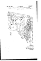
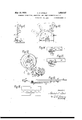
- Figure 1 is a plan view of the well-known Underwood combined typewriting and computing machine arranged for co-operation with the check-writing attachment arranged at the side thereof, forming the subject-matter of this invention.
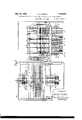
- Figure 2 is a vertical longitudinal central section through the typewriting-computing machine on a plane indicated at 2-2 of Fig-.
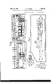
- Figure 4 is a longitudinal vertical section looking from the front at the line 44, Figure 3.
- Figure 5 is a vertical section through the computing basej indicated by the line 55 of Fi re 3.
- igure 6 is a vertical section through the check-printing mechanism indicated by the line 66 of Figure 1. Y
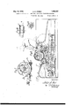
- Figure 7 is an enlarged view of the lefthand end of the check-carrier, on the line 77 of Figure 4.
- Figure 8 is an enlarged detail view in section, showing the manner of connecting the two sections of the rack-driving shafts for flexibility.
- Figure 9 is an end elevation of Figure 8.
- Figure 10 is a three-position view of the check-writing actuating lever and its means to enforce a full strokein both directions.
- Figure 11 is an end view of Figure 10.
- Figure 12 is an enlarged detail view of the cam arrangement that controls the ink-dis when its co-operative figureqvheel isoperative to print.
- Figure 16 is an enlarged view of the paper-cutting type elements.
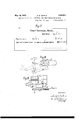
- Figure 17 illustrates, a blank check filled in by the typewriter and check-writer in a manner according to this invention.
- Figure 18 is a fragmentary view illustrating the manner of rotating the ink-supplyroller by a connection to the driving sector.
- Figure 19 is aplan view showing the parts in Figure 18 assembled inoperative position to the type-wheels and ink-rollers.
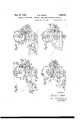
- Figure 20 is a diagrammatic view showing the several parts of the check-Writer positioned as when a check has been inserted at Me rear and the carriage rotated to a point where the feed-rolls have just become effective to feed the check.
- Figure 21 shows the check advanced by the carrier to a point where the cutting platen of the carrier is in position to move in unison with the cutting type faces; the ink-roller against the printing sections; and the aligning elements in full engagement wit-h the active racks.
- Figure 22 shows the printing of the check completed; the ink-roller restored to its supply-roller; and the type-wheels locked while the check-carrier completes its revolution at the end of the forward stroke of the actuating hand lever.
- Figure 23 shows the same parts at the end of the forward stroke of the actuating lever, when the check-carrier has made a complete revolution and the feed-rolls have been released and the check removed.
- Figure 24 shows the word-bearing wheels 111 as they appear by looking at the machine from the rear and at Figure 20 from the right.
- Numeral-keys 25 and alphabet-keys 26, are Numeral-keys 25 and alphabet-keys 26,.
- the step-by-step feeding movements of the carriage are controlled by the usual carriage feed-rack 4O pivotally hung from the platen-frame 36 and in mesh with an escapement-pinion 41, to drive an escapement-wheel 42, formed with the usual teeth to interlock with escapementdogs 43 mounted upon a rocker 43.
- Each type-bar is provided with a heel 44 that strikes a universal bar 45 "to vibrate the rocker 43 at each type impact at the platen to move the dogs 43 into alternate co-operation with the wheel 42 for letter-spacing and also vibrate the ribbon-carrier 46 to raise the ribbon to cover the printing field just before each type impact.
- the machine is provided with the usual decimal tabulator that includes keys 47 and denominational stops 47 that co-operate with a stop 48 adjustably mounted upon a 96 reaches the computing zone a roller 54 of the selectors 52 rides upon a roller 54 centrally located upon the machine to bring a tappet 55 into co-operation with jacks 56 one at a time to depress push rods 57 to rock levers 58 about a fulcrum 59, the inner ends of the levers ( Figures 2 and 3) engaging with cross-bars 6O underlying the pin-bars 50; the levers 58 being so arranged that the extreme right-hand lever of the highest denomination will engage with the pin-carrying bar 50 at the extreme left, which is also the highest denominational position.
- a pendent finger 62 engages with a crank-arm 63 to'rock a shaft 64 and move links 65 to convey a vertical parallel movement to a pin-setting bar 66 ( Figure 4) to depress a pin 61 on any pin-carryingbar raised to a pin-setting position.
- Each register may comprise a series of decimal-order digit-bearing Wheels 67 mounted for rotation upon a shaft 68, supported by side plates 69 of a bracket rising from the base of the casing.
- Gears 70 are loosely mounted at the side of each wheel and connected thereto by a ratchet and a one-Way clutch (not shown) that mesh with the and 81' secured to the casing.
- a general operator comprising a pair of rackms 77, Figure 5, side plates 78 fixed thereto, and a pair of transverse tie-bars 79 and 80, is mounted within the casing and arranged to move through suitable guides 81
- the bar normally stands a little to the rear of the rearmost index-pins 61 and at an elevation that it will pass forwardly under the lower ends of such index-pins as have 'not been forced downward or set but will engage any and all pins of the several bars 50 which have been set.
- an operating shaft 82 having a crank arm 83 at the left-hand end outside the casing, and having inside the casing segmental gears 83" meshing with gears 84 that in turn mesh with rack teeth out in the upper edge of the bars 77 of the general operator.
- the general operator may be moved forward or aekward by the movement of the crank arm 83 outside the casing, and the extreme forward movement of said operator may be adjustably limited by check screws 85 in the casing.
- the left-hand rack-bar 77 of the o rator also is in mesh with a gear 86 rotating upon a screw threaded into the side frame, which in turn meshes with a gear 87 that drives the shaft 74 through a one-way clutch (not shown).
- Such index-pins 61 as have been set in one operation must be restored at the end of the operation.
- a pair of rods 88 and 88 extend transversely across the casing with their ends mounted therein; the rod 88 being stationary and the rod 88 free to turn.
- Bell-cranks 89.joined together by a sleeve are mounted loosel upon each 88 and 88 and connect together by a link 90, to conve a verticalparallel movement to arms of t e bellcranks that are pivoted to ears depending from a pin-restoring plate 91 positioned to underlie the whole series of index-pins 61.
- the rod.88 has a short arm 92 to engage with the under side of the plate 91 to restore the index-pins, and as this operation must take place at the extreme end of the general operators return movement, the rod 88 is provided' with a cam-arm 93, Figure 5, operated by a spring-pressed dog 94 pivotally hung from the bar 77 of the general operator that cams the arm 93 atthe extreme end stroke of said operator, and on the initial forward stroke of the operator the dog 94 will snap under the arm 93 without efiect.
- each bar 50 carries a series of nine index-pins, because in rinting a cipher nothing is added to the register except its denominational value, which is automatically registered by the letter-spacing movement of the carriage to the bars 60, but in simultaneously setting up the equivalent amount in an adjoining mechanism arranged to print the amount upon a bank check the cipher must be set up andprinted. For this reason, each bar 50 is re-arranged to carry a series of ten index-pins 61, but the movement of the general operator'in advancing said bars through a ten-pin movement would upset the whole computing mechanism adapted only for a nine-point movement.
- the ten index-pins are not mounted within to the index-bars 50 as heretofore,but their pin-block is fixed to a plate 96 (see Figure .13) that is secured to the face of the bar 50 by large-headed, shouldered rivets 96 that pass through slots 96 in the plate 96* to guide said plate and' its block of pins for limited longitudinal movements independently of the bar.
- the pins may have a free movement of one pin-space independently of the bar 50, and hence when a in is set the pin will be picked up by the crossat 80 of the general operator and moved the limits of the slot 96, when the bar-driven pin-block picks up its bar 50, and said bar and block of pins will move in unison to register in the usual manner.
- the cross-bar 79 thereof engages the arm 97 that is pend-. ent from the plate 96 and moves the pinblock to the opposite end of the'slot 96, when its bar 50 will be shifted back to its normal position against the comb-plate 51.
- the pin-carrying shuttle has a variable movement of from one to ten unit distances, and from the same movement of the general operator the bar 50 has an operative movement of from one to nine unit distances.
- the arm 97 that is pendent from each plate 96, of the pin-blocks 96 mayterminate at an open slot to embrace a stud 98" rojecting from the side face of the forward end of It is necessary there- Y .erse the adjoining check-printing casing -where the ends take a bearing in. abracket a rack-bar 98 held in a vertical relation under each bar by suitable comb-plate 9 secured to the base of the casing.
- any pin-block 96 is moved by the bar 80 of the above the racks 98.
- These seven shafts ing casing carry a pinion 105 similar to the pinion 100, and each is inmesh with one of a series of seven rack-bars 106 guided by a front comb 107 and an adjustable rear comb 108.
- the operative movement of the bars ,50 is'towards the front of the machine for computing purposes, where the reading of the register-wheels 67 is convenient to the op-' erators position.
- the rack-bars 106 have an operative movement towards the rear;
- a shoe-plate 109 adjustably secured to the comb provides a wide bearing surface to ride over the face of the teeth;
- each bar 106 provides a second toothed rack that is in mesh with a gear 110 secured to a type-printing numeral-wheel 111 mount-ed u on a stationary shaft 112 suspended by t ree brackets 113, Figures 3 and 4, secured to the baseplate of the frame.
- Each type-printing'numeral-wheel 111 that is in mesh with a rack 106 has eleven raised type-faces equally the wheels 111.
- the numeral-bearing wheels 111 are positioned on the shaft 112 to co-operate with four wordbearing wheels 111, one carrying the word cents, another-dollars, a third hundred and a fourth thousand, with two numeralwheels 111 to separate the wheels carrying cents and dollars, two more between dollars and hundred, one between hundred and thousand, and two between "thousand and the outside check-mutilating unit wheel 111?); the series of eleven numeral and word wheels have a capacity to print any amount up to 99 thousand 9 hundred and 99 dollars and 99 cents in numerals and words, and these wheels are grouped together to print at the left-hand portion of the amount line of a check. It is also the purpose of printed in numerals only at the extreme right- .hand end of the amount line on the check,
- each shaft 101 carries two pinions 105 and 105, the latter engaging with rackbars 106 that operate a series of seven digit bearing wheels 111 that are a duplicate of These seven wheels are grouped together, and. to eliminate punctuation between denominations a wide gap 111 is provided between dollars and cents and between the thousandths and hundredths positions.
- the surface-destroying unit on the two left-hand word-wheels 111* and the words. dollars and cents on the third and fourth word-wheels 111, Figure 3, are located normally in line and in the peripheral position 194, Figure 20, while the-zero-characters on all the numeral-wheels 111, 111 and 111, Figure 3, and the words thousand and hundred on the wo left-hand word-wheels 111, Figure 3, shown at the right in Figure 24, are located in the position 195, Figure 20.
- All of the numeral-wheels 111 and 111 arerotat-ed by racks 106 or 106 controlled by the rotation of the pinions 100 and shafts 101.
- the four word- 'wheels 111 and the end wheel 111 are also rotated by a rack 106" similar to the racks 106, but have no pinion driving connections to the shafts 101", and the control of these four wheels by their racks has a distinct function presently to appear.
- the word-wheels hundred and thousand are brought to the setting-up-line position when required, and are under the control of adjoining numeral-wheels at the left hand.
- 600 00 is set up by the typewriting machine to the computing elements, the denominational unit position of the 6 will be established by the associated printed ciphers to set up the type-wheels 111 in proper order, but in the series of wheels 111, the word-wheel hundred .must be brought into printing position notby the ciphers but by the adjoining wheel carrying the 6.
- the rack 106 operating the numeral-wheel to the left of the hundred wheel, Figure 3, has a pin 114 set into the face thereof that: interlocks with a similar pin 114* projecting from the faceof the rack 106 op erating its hundred wheel, Figures ,3, 14 and 15. Hence if the rack 106 is moved rearwardly to the 6 unit position, the pin 114 will release the pin 114 to the action of a spring 118 to automatically move the hundred wheel 111 one space to the setting-up line to supersede the blank type unit.
- the wheel carrying the word thousand operates in a similar manner, and while the dollars and cents wheels are also shown provided with springpressed fingers 116 and 116, their function is entirely different, as will presently be seen.
- 119 indicates a driving shaft having end bearingswithin the brackets 113 and operated by a crank-arm or operating lever, ⁇ 120 secured to one-end of the shaft to pass upwardly through a gap between the two frames and the free end provided with a handle 120.
- This arm 120 swings between twoadjustable stop positions, indicated at 121 and 121 ( Figure 10) as set-screws threaded through earson abracket 122 secured to the base adjacent the lever, said bracket formed with fine arcuate V-teeth 122a'c'r0ss the upper edge to cooperate with atwo-way spring pressed dog 123, pivoted to said lever to overhang the toothed edge of the bracket to force a full stroke of the lever in both directions when once started, commonly known as a full-stroke mechanism.
- the drive shaft 119 is approximately directly under the wheel shaft 112, and, at a point'where a gap is formed between the series of word-wheels 111 and the series of numeral-wheels 111, a cam 124 is secured to the shaft 119 to operate a short arm 125 of a lever 126 secured to a shaft 126 supported by two ears formed at the side edges of a bracket 127.
- the lever 126 isbifurcated to engage with a stud 128" on a short crank-arm 128 securedto a rock-shaft 129 that extends across the machine under the whole series of rack-bars 106, 106i and 106where the ends take bearings within u right ears 129' rising from the base-plate.
- a pair of arms 130 have hubs that are pinned to the shaft 129 and the upper ends of both arms are pivotally connected to one end of links 131 that extend forwardly at either side ofeach group of bars 106 and 106, and the free ends are joined by two tie-rods 132, spaced relatively to each other a dimension equal to the pitch or the distance between two adjoining teeth of 'the racks 106 and normally raised above the racks by a spring 133 secured between a short arm of each link 131 and an ear on each arm 130.
- the forward upper ends of the links have a cam face 131 operative to co-act with a round nose cam-bar 1 34 fixed at each end to the brackets 113 to overhang the whole series of links 131.
- each number-wheel 111 has eleven printing units and the associated gear has eleven teeth, which provides for comparatively large teeth and a proportional wide gap etween the teeth of the co-operating rack-bars 106, and enables a fairly large rod to be employed to withstand the strain of operating the racks and wheels.
- the casing of the check-writer may be divided into three sections, the base A, the enclosing casing B and a hood .C that covers the printing elements.
- the hood and casing are formed with interlocking lugs 135 pivotally tied together by a fulcrum-rod 135, and the hood may be locked down at the front side by eyebolts 136 pivoted to the casing and positioned at each side to ,pass
- a check-carrier 139 is mounted, comprising a cylinder or tubular section with heads at each end having interior and exterior hubs to provide a long wearing surface on the stationary shaft.
- the tubular section is formed with two longitudinal slots 140 and 140 extending from head to head with a short bridge section 140 between what corresponds to the gap between the series of word-wheels 111* and the series of numeral-wheels 111, and indicates an unused section of the amount line of the check.
- a U-shaped channel-piece 141 has side flanges secured to the inner face of the cylinder, with side walls that align with the edges of the i slots and provide .a continuous housing on the cylinder.
- Each platen-section 142 has two shouldered studs 142' that pass from the lower face of the platen down through a clearance hole in the adjacent wall of the housing, where the free ends terminate at a large head 142 that is flat on the side towards the housingto receive the forked ends of a spring comb-bar 143 secured to the inner face of the cylinder.
- a cam 144 is fixed to the staredetermined point, and the lower ends of t e studs 142 contact with their respective cams 144, and the associated platen-sections are raised above the periphery of the cylinder and held there by a dwell on the cam for a predetermined interval and then ride off the cam and are restored by the individual springs 143 to bottom withinthe housing with the outer faces of the platen-sections flush with the face of hubs of the cylinder by a pin 151.
- the forward movement of the arm 120 swinging between its two stop positions 121 and 121 rotates the cylinder 139 through one complete revolution or cycle through the forward movement of the pawl 148 driving the disk 150, and, when the movement of said arm is reversed, the pawl will leave the disk 150 and cylinder 139 at a position where the pawl will re-engage the disk at the end of the return stroke; hence the carrier 139 makes a complete cycle on the forward stroke and remains inactive during the full return stroke of the arm 120.
- the check-carrier has two leading-edgealigning stop-pins 152 which are carried on the ends of two flexible fiat springs 152 secured to the inner wall of the cylinder with the pins passing through clearance holes on the walls thereof to project slightly be-- yond the outer face of the cylinder.
- a paper-deflector 153 secured to the inner end walls of the hood C, passes through an opening in the top wall with the forward end curving around the under side of the carrier 139 where the free ends overla the edge of the front apron of the casing to guide the work-sheet, with portions of the deflector cut away to allow clearance for the platens 142. T he check may be further guided by a side-edge gage 154 secured to the left-hand side of the deflector.
- the paper-feeding means co-operating with the cylinder 139 comprises three rollers 155, Figures 1 and 6, which bear against the face of the cylinder 139 in front of the printing wheels 111, and which may be flexibly mounted individually upon a rock-shaft 156 that has bearings at the side walls of the casing, the free right-hand end passing through the casing and provided with a finger-piece 157 to release all three rollers from pressure. against the cylinder face when desired.
- Another feeding element intermittent in its operation, comprises three rolls 158 mounted for rotation upon a rod 158 fixed at both ends to side arms 159, which in turn are secured to a rock-shaft 160 journaled in the brackets 113, the rolls being urged through openings in the deflector 153 toward the cylinder 139 by a spring 160.
- the rotating of the cylinder might effect an immediate grip on the paper, or the grip might be delayed an instant and change the writin -line position, or the grip might first take effect at one corner and result in an angular entry, or the paper might not enter atall.
- the feedrolls 158 normally are cammed away from the face of the cylinder and the insertion of the check allows the leading edge to pass between the cylinder 139 and rolls 158 to the position of the stop pins 152, and the initial movement of the cylihder releases the rolls 158 to be spring-pressed against the face of the check to the rear of the leading edge, and hence a positivegripping feed of the check through the printing wheels is effected.
- a cam-plate 161 To this end a cam-plate 161.
- Figure 7 is secured at the left-hand end of the cylinder between the head and the disk 150 that engages the inner end of the adjacent arm 159 at the end of the forward stroke of the arm 120, which provides an entering space between the rolls and the cylinder, and at the initial forward stroke ofsaid arm 120 the rotation of the cylinder in the direction of the arrow in this figure will release the rolls to the action of the spring 160 and paper-feeding will take place immediately.
- the forward movement of the crank-arm 1'20 conveys a full revolution to the cylinder 139, and near the end of the forward stroke of said crank-arm the cam- -plate will force the rolls 158 to the inoperative position of Figure 7.
- the check has been printed and if the movement of the cylinder does not'eject the check, there is not ing to prevent it from being' withdrawn by the handexcept the pressure from the rolls 155, which ma be released by the finger-piece 157 and t e check withdrawn. It will be noted that the rolls 155 are positioned to engage at the two edges of the checkiand that the middle roll is positioned to the blank space between the two series of type-wheels;
- the inking elements consist of a roller 162 made up in sections that rotate freely upon a rod 163 carried by two side arms 164 that are fixed to the end of a rock-shaft 165 journaled in the. two outer brackets 113.
- the arm 164 at the right-hand end, Figure 12 has a finger 164 that enters the swee of a camplate 166 adjustably secured tot e adjacent head of the cylinder-139 b a screw 166 passing through an elongate( hole in the plate and threaded into the cylinder head, providing means to advance orretard the cam, for
- the rolls provide ink for the type-faces of the printing type-wheels, and, as shown at Figure 3, the
- sections are arranged for the grouping of the type elements to provide ink of one color for the numeral-wheels and ink of another color for the word-wheels, or they may all be of a uniform 00101 if desired.
- the rolls 162 are comparatively small in diameter and made of felt, and their capacity for saturation is limited; hence an ink-supply roller 167, also of felt and made up in sections, is carried by a shaft 168 journaled in the two end brackets 113.
- the rolls 162 are urged towards the larger rolls 167 by a spring 164" connected between a spring stud 0n the arm 164 and a similar stud on the bracket 113 at each side, and when the rolls 167 are rotated by the shaft 168 the rolls 162 roll over the surface thexeof'hnd a uniform density of ink is maintained in the smaller roll.
- one end of said shaft outside of the bracket 113 may be provided with 'a toothed ratchet-wheel 169, Figures 18 and 19, enclosed on two sides by disks 169" to retain and guide a ratchet-toothed rack-bar 170 pivotally connected to the face of an arm of the gear-sector 145 and engaging the wheel 169 in one direction by its own wei ht and riding over said wheel to follow the xed radial movement of its pivot in the sector.
- the numeral-wheels 111 have eleven printing units distributed around the rim of the wheel at uniform distances; one unit for each of the numbers 0 to 9 and one blank surface-mutilating unit.
- the surface-mutilating unit of each number-wheel is normally positioned at a setting-up line position, where any and all of the selected type-faces are prematurely grouped and subsequently advanced to the printing position as a wholeline-unit. As every check made out is in dollars and cents, these two words may be in permanent alignment with the surface-mutilating units, but the two word-wheels for hundred and thousand have a surfacemutilating or blank unit in alignment'with this setting-up line position when the amounts selected are below their denominational value.
- Every check that is printed employs the whole linear series of rinting elements that cover the entire length amountline. and when an amount in numerals and words is selected by the adding elements these selected units displace corresponding surface-mutilating blank units, and hence such portions of the amount line not used by the amount units in numbers and words will be destroyed by the blank units to prevent the surface from being used a second time to make any changes in the original line of print.
- the platen-sections 142 have transverse sharp V-cutting teeth throughout their length, and that these teeth align with V- grooves cut across the type-faces, indicating in this figure the letters cents.
- the type faces are printing faces, a flat type-face section is preserved between each V-groove as an ink-carrying surface.
- the typewheels 111 and 111 are mounted upon the shaft 112 for a free running fit without unnecessary end motion, it would be practically impossible to cut a continuous platen-bar with V-teeth that would align perfectly with the grooves in the whole series of wheels 111; hence the platen-sections 142 are provided with slight endwise movements, as indicated by heavy lines for a slight clearance space between adjoining platen-sections at Figure 4, which permit the teeth of the individual platen-sections to adapt themselves to the grooves in the wheels for cutting alignments.
- a blank check 153 shown at Figure 17, is adjusted to the typewriter platen 84 and the date indicated at a is typed; the payees name entered at b and the amount of the check typed on the same line as shown.
- the numeral-keys on the typewriter depress the' fingers 62 that operate the rock-shafts 64 to depress their bars 66, which in turn depress the underlying indexpins 61 in their respective index-bars 50.
- the crank-arm 83 is drawn forwardly, and the cross-bar 80 will move forwardly and pick .up these pins that have been depressed and move their associated indexing-bars in unison therewith to the end of the stroke as their denominational positions may indicate.
- index-pin will be moved through seven units of space and will move its associated indexing-bar through six units to set up the six position on its index wheel.
- the other four depressed index pins will move through one unit distance and not affect their index-bars 50.
- the movement of the first pin through seven unit spaces will carry its rack-bar 98 the same distance, and rotate its pinion 100, shaft 101 and the two pinions 105and 105 to move the racks 106 and 106 a seven unit distance to rotate their numeral-wheels 111 and 111 to bring the numerals 6 to the setting-up-line position, one numeral 6 before the word "hundred, whose wheel has been released, and one at the denominational hundreds position in the wheels 111.
- Printing the four ciphers will set up four pins 61, and near the end of the stroke of the crank-arm 83 the bar 80 will pick up these four pins and move them one unit distance by moving their shuttles 96 and not disturbing their racks and this one unit movement of these four shuttles will rotate their shafts 101 to move the racks 106 and 106 to cause ciphers to supersede the mutilating units in the setting-up line position.
- the denominational position of the 6 is hundreds, and the rack 106, in moving rearward through the first unit distance, will release the rack 106 to the action of the spring 118, and the pin 115 will move from a position shown at Figure 6 to that of Figure 14, where the rack is arrested and locked by the stud 115 between the two arms 116 and 116, which automatically shifts the surface-mutilating blank type-face to bring the word hundred into alignment wit-h the setting-up position, and, as already described, the setting up of an amount in the word line simultaneously sets up numerals in the second group 111 at the end of the line.
- the check is removed from the typewriter and adjusted to the check-writer with the top edge down and the printed. face to the rear against the deflector 153, with the left-hand edge against the gage 154 and the leading edge resting against the stop-pins 152.
- crank-arm is drawn forward from the position of Figure 6 to that of Figure 20, and during the initial movement of the crank the roller 158 has passed from the control of the cam 161 and is spring-pressed against the face of the check. A further forward movement of the crank brings the several operative parts into co-operative positions, as
- a stripping plate 172 may be secured to the frame, with the edge positioned to ride over the face of the cylinder and strip the edge of the check from tlie pins that pass through grooves in the p ate.
- the seven shafts are divided into two sections 101 and 101 and are joined together by a flexible coupling that will promote a joint rotation in one direction during one interval, and during another interval permit one section to remain inactive while the other advances in the same direction.
- the shafts 101 have a direct connection to the selecting'elements and the shafts 101" are connected directly to the rack 106.
- Each shaft 101 has a sleeve 173 secured thereto by a pin 174 with the sleeve abutting the face of the bracket 104. The inner end of the shaft 101 enters the sleeve 173 freely with the end thereof abutting the end of the shaft 101.
- the edge of the sleeve 173 that overhangs the shaft 101' is stepped or. notched to co-act with a pin 174 driven transversely through the shaft to check the action of a s ring 175 coiled about exing.
- a locking bar 176 is positioned over the rack-bars 98 and given a sliding parallel up and down movement, through being mounted upon screws 177 that pass through angular slots in the bar and. hold the bar against the face of a cross-bar 178 and spring-pressed in one direct on by a spring 179.
- a curved trip-arm 180 is secured at one end of a rock-shaft 181. journaled in cars on the guides 81" at each side frame, and provided with a spring 182 to urge the end of the trio-arm 180 against the edge of the bar 77.
- The'rock-shaft 181 carries an arm, 183 that extends rearwardl-y over the upper edge of the locking bar 176 and also the seven bars 60 for purposes presently to be described.
- the rack-bar 77 of the general operator always has a uniform forward movement, and the edge thereof adjacent the end of the overlying end of the cut-away portion will cam the end of the trip 180 and cause it to ride to the higher edge of the bar, causing the arm 183 to drop and press upon the top edge of the .slide 176 and depress 1 rear.
- Figure 2 a push-key 184, through the front wall of the typewriter frame, traverses the machine where the rear free end s pivoted at 184 to the lower end 0 of a bell-crank 185, swinging about a pivot 186 with a short arm 185 carrying a stud 187 to engage with an arm 188 that rocks a .shaft 189 and arms 189 carrying the roller 54 between them.
- the key 184 By pushing in the key 184, the
- roller 54 is shifted out of the path of the rollers 54 on the selectors 52, and the carriage may be moved freely through the adding zone and the selectors will remain inactive.
- a pin 191 projecting from the push-key 9 184 out-through a slot 192 in the side frame w ll lock the key indefinitely in a pushed-in position by dropping back of a shoulder 193 ,formed in the slot, as shown and described in the aforesaid patent to Hart.
- crank-arm 83 is now moved to the The initial movement dro s the trip- ,arm 180 into the slot in one rack-bar 77 of the general operator and raises the arm 183 to the position shown at Figure 5, which releases the locking bar 176 to its spring, to withdraw the bar from the teeth of the still stationary racks 98.
- the forward toothed section of the bar 77 which is in train with the gears 86 and 87, will rotate the transferring elements 73 to co-operate with any pinion 75 that has moved into their field during the forward stroke of the rack 50 for a carry-over register.
- the cross-bar 79 will first pick up the pendent arm 97 of any active rack 50 and move the pin-carrying shuttle one unit space to the rear and then convey a rearward movement to the bars 50 to their stop positions against the comb-plate 51.
- the dog 94 will vibrate the. cam-arm 93. rod 88 and arm 92 to lift the plate 91 against the lowerends of any depressed indexing pins 61 to force the'pins upwardly to an inactive position above the field of the bar 80, and then drop the camarm 93 to restore the plate 91.
- the shafts 101 and 101" and pinions 105 will restore the racks 106 and rotate numeral-wheels 111, and near the end of the return stroke.
- crank-arm 83 After the setting up of the indexing pins, the crank-arm 83 is moved forwardly until checked by the general operator striking itsstops, and the lever is left in this forward position. The check is removed from the typewriter and adjusted to the adjoining check-writer, and the crankarm 120 moved forwardly against its stop 121, which prints and ejects the check, and
- the selective mechanism at each operative period rotates the adding accumulator wheels a predetermined number of digit unit distances of one to nine, andsimuL- taneously rotates type-wheel printing elements unit-distances of one to ten; that the type-printing wheels are prematurely assembled at a normally inoperative printing position, and subsequently carried as a longitudinal unit through a fixed printing zone predetermined by a cooperatin normally inoperative cutting platen mova le with a rotary check-carrying cylinder, makin one complete revolution at every check-printing operation; that the type-inking means comprise an ink-sup 1y roller and an ink-distributin roller t at is so timed that ink is supplie only to such type-faces that are active in the next printing operation; that the inking rollers are assembled in sections, and each alternate section saturated with a different colored ink to give a contrast between the printed numerals and the printed words
- the hinged hood-section Cl that may be swung back against stops to give easy access to the typewheels for cleaning purposes, or for supp ing ink to the supply rollers when required and that by turning the check-carrying cylinder by hand the cutting platen-sections may be rotated to a position to be cleaned by a brush, and then restored and timed correctly through the adjustment of the disk 150 to the driving pawl148; and the Wheels 111, as a series, may be rotated step by step by first setting all the 9 digit-pins, and then in"- ing the arm 83 slowly forward to successively rotate the ten cutting type-faces of each wheel through a position accessible to a cleaning brush.
- the active cutting type-wheels denote their denomination- :11 values by automatically bringing the denominational words hundred or thousand into printing alignment, and while the words dollars and cents are shown and described as fixed units in the setting-up line, it will be understood that these two wheels may be arranged to move in and out of the setting-up line similar to the words hundred and thousand, in which case the normal setting-up line will present a continuous line of surface mutilating blank cutting elements: and that in adjusting the blank check to the rear of the check-carrier against fixed stops in advance of the feed-roll posit on, said feed-rolls become operative at such a time and in such a manner as to prevent any possibility of the check skewing out of proper alignment: said rolls becoming both feeding and paper-gripping elements to hold the check in proper relation to the rotary checkcarrier.
Landscapes
- Engineering & Computer Science (AREA)
- Physics & Mathematics (AREA)
- Computer Hardware Design (AREA)
- Computing Systems (AREA)
- General Physics & Mathematics (AREA)
- Theoretical Computer Science (AREA)
- Character Spaces And Line Spaces In Printers (AREA)
Description
H. H. STEELE 1,858,027
COMBINED TYPEWRITING, COMPUTING, AND CHECKPRGTECTING MACHINE May 10', 1932.
. 1924 8 Sheets-Sheet 1 Filed Nov l 2 Q i m u nvenfof: mix W I Arorn H. H. STEELE May 10, 1932.
COMBINED TYPEWRITING, COMPUTING, AND CHECK PROTECTING MACHINE Filed Nov. 12. 1924 8 Sheets-Sheet 2 k m m zmz Q? x Q In venfor /M% M y Afforngf y 1932- H. H. STEELE COMPUTING, AND CHECK PROTECTING MACHINE COMBINED TYPEWRITING,
Filed Nov. 12. 1924 8 Sheets-Sheet 5 In venror:
WWW
May-l0, 1932.. H. H. STEELE 1,858,027
COMBINED TYPEWRITING, COMPUTING, AND QHECK PROTECTING MACHINE Filed Nov. 12, 1924 8 sheets-sheet 4 y //l m+ 3 & lnvenfor:
by Aria/n May 10, 1932. H. H. STEELE 1,853,027
COMBINED I'YPEWRITING, COMPUTING, AND CHECK- PROTECTING MACHINE Filed. Nov. 12, 1924 8 Sheets-$heet 5 y 10, 1932- H. H. STEELE 1,858,027
COMBINED TYPEWRITINGYCOMPUTING, AND CHECK PROTECTING MACHINE Filed Nov. 12, 1924 8 Sheets-Sheet 6 y 10, 1932- H. H. STEELE 1,858,027
COMBINED TYPEWRITING, COMPUTING, AND CHECK PROTECTING MACHINE Filed Nov. 12, 1924 8 Sheets-Sheet 7 Fig. /7.
F IRST NATIONAL BANK.
NEW YORK, May I924.
agzbllzcwr% John Doe CZ 600.00 nnunnnummmun|"mu|mmmun|[m|uunmmnnmummmnii l-"ll'l..."||-IHIIIIHFH1H552 IIIIII'IINHHII uim4:;:-|l..L.A n.fiz.milIn" 42111;: WW3; lllllllllmllll 4553 "1111' 111 IIIHIII In venror:
y Afforn H. H. STEELE May 10, 1932.
COMBINED TYPEWRITING, COMPUTING, AND CHECK PROTECTING MACHINE Filed Nov. 12, 1924 8 Sheets-Sheet 8 flrrorne Patented May 10, 1932 UNITED STATES PATENT. OFFICE HERBERT STEELE, OF LYNBROOK, NEW YORK, ASSIGNOR, BY KESNE ASSIGNMENTS, TO ELLIOTT-FISHER COMPANY, OF NEW YORK, N. Y., A CORPORATION OF DELAWARE COMBINED TYPEWRITING, COMPUTING, AND CHECK-PROTECTING MACHINE Application filed November 12, 1924. Serial No. 749,401.
This invention relates to bank-check writing and is herein shown as applied to a coinbined typewriting and computing machine of the Underwood-Hanson type as'disclosed in the patent to Hart, No. 1,190,171, dated July 4, 1916, where numeral-keys, when depressed to record a number, set up individual index-- subsequent movement the bars to register their individual values on their associated accumulator-wheels, simultaneously register the same values upon a series of check-print ing'type-wheels that subsequently record the same values in a difierent form in dollars and cents upon the same work-sheet previously printed to set up these values.
The preparation of the weekly cash payroll in large corporations is a burdensome and costly addition to the overhead expense.
The drawing of a pay-roll from the bank in mixed currency, separating it in small amounts, filling envelopes previously markedfor identification and then distributing them, forced many of the railroads to adopt bimonthly pay-days. The development of the pay-roll check has changed all this, and today railroads and many large corporations are using the pay-roll check as a medium for a weekly settlement with their employees. In the preparation of these checks, the check is first typewritten for the insertion of date, payees name and amount, and'then some one of the many forms of check-writing protectors is employed as a separate operation to enter the amount in the body of the 'checli, which must subsequentlybe signed or counter-signed.
These so-called check-writers are vprotective machines only and have no labor-saving qualities, and as they do not preserve a record of the amount entered upon each check, the final checking up of the machine-written-checks for a total to balance with the pay-roll records, opens up gaps for errors to creep in, and is still an expensive method.
In the present invention, the combined mechanisms produce a finished product, a check that is complete except for the signature. The typewriter prints the 'date, the payees name and, at the right-hand end of the same line, the amount of the check in numerals, and, simultaneously with the printing of these numerals, automatically sets up similar denominational values in dissimilar forms; one form as a register Where each check value is accumulated for a grand total, and the other form as printing elements that shred or emboss the set-up amounts in words and numerals by inked paper-cutting typefaces at the left-hand end of the amount line,
and again in numerals only at the extreme right-hand end of the line; thus making three different amount-entries onthe check, one typewritten, and two indelibly cut in the paper to provide for a' reater protection against check-raising. urthermore, the registering of the amount of each check at the register-wheels provides a totalto balance with the pay-roll records, or if employed in a bank or a treasurers ofiice, provides a total for the days transaction in disbursed funds.
In a combination machine of this character, the printing of a cipher by the typewriter adds nothing to the computing elements except a denominational position, but the value of this cipher must be transferred to the check-printing elements to print its denominational'value on the check; and hence a general operator that transfers the set-up unit values in the digit bars to the register-wheels in units of 1 to 9 must simultaneously transfer an extra unit into the check-printing wheels to provide for the printing of the cipher on thecheck. To these ends each digit bar, which has heretofore carried nine index pins, in the present invention carries a series of tenindex pins mounted Within a shuttle-bar secured loosely to the face of each digit-bar to have a free and independent movement of one digit dimension, before any movement can be conveyed to said bar, and to have a positive connection to its checkprinting rack-bar to move the latter distances of from one to ten digit-dimensions, but the digit-bar will only be operative from one to nine digit-dimensions, as heretofore.
Another feature rovides for a two-color ink distribution to t e paper-cutting faces of the type, that certain words may be written in one color out-he check and certain numerals in another color for a contrast and quick reading of the amount.
Another feature provides for a 'rotary check-carrier with a normally inoperative paper-cutting platen and a series of normally inoperative paper-cutting type-elements, that at a predetermined interval in the carriers 'movement rotate in synchronism with the carrier during a predetermined interval while the platen and type co-operate to shred the amount in words and numerals in the body of the moving check, and during acontinuous rotation of the carrier.
Another feature provides for the setting up of the full amount in dollars and cents in a continuous line in both words and numerals by a key-manipulated type-printing operation, and for subsequently printing the full line of set-up cutting type-faces at a single operation.
Another feature is the timing of the inking element, that ink will only be applied to such type-faces that have been selected for printing on the check, and during the interval that the inking rollers are inactive, they engage with a larger rotating ink-supply roller to maintain a uniform distribution of ink.
The paper-cutting t -faces are coated with a thick indelible in which necessitates frequent cleanin to prevent smearing at the back of the chec and, for this purpose, the upper frame-section is hinged to swing back to give access to the-cutting ty 'e-faces and to the paper-cutting platens or cleaning purposes.
Another feature consists of a series of rackbars that move to a fixed-stop position to operate the register-wheels to register a predetermined value, and a second series of rackbars that move in unison with the first series to set up a similar value on check-printing wheels; the two series of racks having a flexible connection that enables the check printing racks .to advance a predetermined distance in the same direction and independently of the register-racks, to print the set up value on the check.
Paper mutilating check protectors, as heretofore described, in printing a small amount, like ten dollars, only mutilate a very short section of the amount line, and it has been an easy matter to erase this short printed section and substitute a new line for a larger filllllollnt in the unused area of the amount right-hand end of the check-carrier and the Another feature of this invention provides for sectional inked paper-cutting elements for cutting a blank surface-destroying area through the entire length of the amount line on the check, and which elements are automatically displaced by word and numeral paper-cutting types predetermined by a key manipulation, thus mutilating the area not employed in writing the amount on the check. an efl'ectively preventing any subsequent change in the amount, because it is a wellknown fact that a type-cut surface on a check cannot be recut without detection.
Another feature consists of a normallyinoperative aligning device to bring the entireline of paper-cutting type-faces into longitudinal alignment after a key-manipulated assemblage and during their active period in printin the check.
Anot er feature consists of'a rotary checkcarrier having aligning fixed stops for the leading edge of the check, and a plurality of normally-inoperative feed-rolls that become effective to feed the check at the initial movement of the carrier.
Other features and advantages will hereinafter appear.
In the accompanying drawings,
Figure 1 is a plan view of the well-known Underwood combined typewriting and computing machine arranged for co-operation with the check-writing attachment arranged at the side thereof, forming the subject-matter of this invention.
Figure 2 is a vertical longitudinal central section through the typewriting-computing machine on a plane indicated at 2-2 of Fig-.
and check-writing elements as though the top section of the frame had been removed.
Figure 4 is a longitudinal vertical section looking from the front at the line 44, Figure 3.
Figure 5 is a vertical section through the computing basej indicated by the line 55 of Fi re 3.
igure 6 is a vertical section through the check-printing mechanism indicated by the line 66 of Figure 1. Y
Figure 7 is an enlarged view of the lefthand end of the check-carrier, on the line 77 of Figure 4.
Figure 8 is an enlarged detail view in section, showing the manner of connecting the two sections of the rack-driving shafts for flexibility.
Figure 9 is an end elevation of Figure 8.
Figure 10 is a three-position view of the check-writing actuating lever and its means to enforce a full strokein both directions. Figure 11 is an end view of Figure 10. Figure 12 is an enlarged detail view of the cam arrangement that controls the ink-dis when its co-operative figureqvheel isoperative to print.
Figure 16 is an enlarged view of the paper-cutting type elements.
Figure 17 illustrates, a blank check filled in by the typewriter and check-writer in a manner according to this invention.
Figure 18 is a fragmentary view illustrating the manner of rotating the ink-supplyroller by a connection to the driving sector.
Figure 19 is aplan view showing the parts in Figure 18 assembled inoperative position to the type-wheels and ink-rollers.
Figure 20 is a diagrammatic view showing the several parts of the check-Writer positioned as when a check has been inserted at Me rear and the carriage rotated to a point where the feed-rolls have just become effective to feed the check.
Figure 21 shows the check advanced by the carrier to a point where the cutting platen of the carrier is in position to move in unison with the cutting type faces; the ink-roller against the printing sections; and the aligning elements in full engagement wit-h the active racks.
Figure 22 shows the printing of the check completed; the ink-roller restored to its supply-roller; and the type-wheels locked while the check-carrier completes its revolution at the end of the forward stroke of the actuating hand lever.
Figure 23 shows the same parts at the end of the forward stroke of the actuating lever, when the check-carrier has made a complete revolution and the feed-rolls have been released and the check removed.
Figure 24 shows the word-bearing wheels 111 as they appear by looking at the machine from the rear and at Figure 20 from the right.
Numeral-keys 25 and alphabet-keys 26,.
when depressed, operate their key-levers 27 about a fulcrum rod 28 to vibrate bell-crank 29 about a fulcrum 30 and cause their associated type-bars 31 to swing upwardly and rearwardly about a fulcrum wire 32 to cause the type-faces 33 to print at a common printmg point on the front side of a rotatable platen 34 mounted upon a shaft 35 that takes bearings in the two ends of a platen-frame 36 carried by a carriage 37 that moves from rightto left upon guide-rods 38 and 39, under the influence of a spring motor (not shown) connected to the carriage. The step-by-step feeding movements of the carriage are controlled by the usual carriage feed-rack 4O pivotally hung from the platen-frame 36 and in mesh with an escapement-pinion 41, to drive an escapement-wheel 42, formed with the usual teeth to interlock with escapementdogs 43 mounted upon a rocker 43. Each type-bar is provided with a heel 44 that strikes a universal bar 45 "to vibrate the rocker 43 at each type impact at the platen to move the dogs 43 into alternate co-operation with the wheel 42 for letter-spacing and also vibrate the ribbon-carrier 46 to raise the ribbon to cover the printing field just before each type impact.
The machine is provided with the usual decimal tabulator that includes keys 47 and denominational stops 47 that co-operate with a stop 48 adjustably mounted upon a 96 reaches the computing zone a roller 54 of the selectors 52 rides upon a roller 54 centrally located upon the machine to bring a tappet 55 into co-operation with jacks 56 one at a time to depress push rods 57 to rock levers 58 about a fulcrum 59, the inner ends of the levers (Figures 2 and 3) engaging with cross-bars 6O underlying the pin-bars 50; the levers 58 being so arranged that the extreme right-hand lever of the highest denomination will engage with the pin-carrying bar 50 at the extreme left, which is also the highest denominational position.
When a numeral-key 25 is depressed, a pendent finger 62 engages with a crank-arm 63 to'rock a shaft 64 and move links 65 to convey a vertical parallel movement to a pin-setting bar 66 (Figure 4) to depress a pin 61 on any pin-carryingbar raised to a pin-setting position.
Each register may comprise a series of decimal-order digit-bearing Wheels 67 mounted for rotation upon a shaft 68, supported by side plates 69 of a bracket rising from the base of the casing. Gears 70 are loosely mounted at the side of each wheel and connected thereto by a ratchet and a one-Way clutch (not shown) that mesh with the and 81' secured to the casing.
a square shaft 74, which rotate carry-over pinions when a tooth 76 on an wheel 67 enters a carry-over position. Eac 1 carrying pinion 75 has a three-toothed wheel 75' connected'thereto which engages with a wheel 72 of the next higher denomination. I
\Vhen the bars 50 stand in their normal positions, their index-pins 61 stand directly under their respective bars .66 and lie far enough below the same so that the de ression of said bars will not engage the in ex-pins of the bars unless the rear end of a bar is raised by its decimal-order selecting lever 58. A general operator, comprising a pair of rackms 77, Figure 5, side plates 78 fixed thereto, and a pair of transverse tie- bars 79 and 80, is mounted within the casing and arranged to move through suitable guides 81 The bar normally stands a little to the rear of the rearmost index-pins 61 and at an elevation that it will pass forwardly under the lower ends of such index-pins as have 'not been forced downward or set but will engage any and all pins of the several bars 50 which have been set.
Mounted in suitable bearin s in the side walls of the casing and exten ng above the bars 50, is an operating shaft 82 having a crank arm 83 at the left-hand end outside the casing, and having inside the casing segmental gears 83" meshing with gears 84 that in turn mesh with rack teeth out in the upper edge of the bars 77 of the general operator. Thus the general operator may be moved forward or aekward by the movement of the crank arm 83 outside the casing, and the extreme forward movement of said operator may be adjustably limited by check screws 85 in the casing. The left-hand rack-bar 77 of the o rator also is in mesh with a gear 86 rotating upon a screw threaded into the side frame, which in turn meshes with a gear 87 that drives the shaft 74 through a one-way clutch (not shown).
Such index-pins 61 as have been set in one operation must be restored at the end of the operation. A pair of rods 88 and 88 extend transversely across the casing with their ends mounted therein; the rod 88 being stationary and the rod 88 free to turn. Bell-cranks 89.joined together by a sleeve are mounted loosel upon each 88 and 88 and connect together by a link 90, to conve a verticalparallel movement to arms of t e bellcranks that are pivoted to ears depending from a pin-restoring plate 91 positioned to underlie the whole series of index-pins 61. The rod.88 has a short arm 92 to engage with the under side of the plate 91 to restore the index-pins, and as this operation must take place at the extreme end of the general operators return movement, the rod 88 is provided' with a cam-arm 93, Figure 5, operated by a spring-pressed dog 94 pivotally hung from the bar 77 of the general operator that cams the arm 93 atthe extreme end stroke of said operator, and on the initial forward stroke of the operator the dog 94 will snap under the arm 93 without efiect.
This description up to this point covers briefly the Underwood-Hanson computing mechanism, further details of which may be had from the Hart patent referred to. I
In the old computing mechanism fust described, each bar 50 carries a series of nine index-pins, because in rinting a cipher nothing is added to the register except its denominational value, which is automatically registered by the letter-spacing movement of the carriage to the bars 60, but in simultaneously setting up the equivalent amount in an adjoining mechanism arranged to print the amount upon a bank check the cipher must be set up andprinted. For this reason, each bar 50 is re-arranged to carry a series of ten index-pins 61, but the movement of the general operator'in advancing said bars through a ten-pin movement would upset the whole computing mechanism adapted only for a nine-point movement. fore from a fixed movement of the general operator, to transmit a new ten unit movement to the check-printing mechanism and the old nine unit movement to the computing mechanism. To this end, the ten index-pins are not mounted within to the index-bars 50 as heretofore,but their pin-block is fixed to a plate 96 (see Figure .13) that is secured to the face of the bar 50 by large-headed, shouldered rivets 96 that pass through slots 96 in the plate 96* to guide said plate and' its block of pins for limited longitudinal movements independently of the bar. This construction provides that the pins may have a free movement of one pin-space independently of the bar 50, and hence when a in is set the pin will be picked up by the crossat 80 of the general operator and moved the limits of the slot 96, when the bar-driven pin-block picks up its bar 50, and said bar and block of pins will move in unison to register in the usual manner. On the return stroke of the general operator the cross-bar 79 thereof engages the arm 97 that is pend-. ent from the plate 96 and moves the pinblock to the opposite end of the'slot 96, when its bar 50 will be shifted back to its normal position against the comb-plate 51. Thus from a uniformly fixed movement of the general operator the pin-carrying shuttle has a variable movement of from one to ten unit distances, and from the same movement of the general operator the bar 50 has an operative movement of from one to nine unit distances.
The arm 97 that is pendent from each plate 96, of the pin-blocks 96 mayterminate at an open slot to embrace a stud 98" rojecting from the side face of the forward end of It is necessary there- Y .erse the adjoining check-printing casing -where the ends take a bearing in. abracket a rack-bar 98 held in a vertical relation under each bar by suitable comb-plate 9 secured to the base of the casing. When any pin-block 96 is moved by the bar 80 of the above the racks 98. In the typewriting element, provision is shown for an adding zone of seven digits, with seven jacks 56 operating seven levers 58 and seven index-pin-bars 50. Hence there are seven shafts 101 that lie in parallel horizontal planes above the racks 98, and the pinion 100 secured thereto is positioned to align with the rack position. These seven shafts take an end bearing in a bracket 102, Figure 3, secured to the base of the computing casing and extend rightward to trav- 103. As these shafts are long and comparatively small in diameter, an intermediatebracket 104 gives a center-support for the seven shafts, and said shafts are divided into two sections, one-section 101 within the computing casing and the other section 101* within the check-printing casing. This division is made for purposes presently to appear.
These seven shafts ing casing carry a pinion 105 similar to the pinion 100, and each is inmesh with one of a series of seven rack-bars 106 guided by a front comb 107 and an adjustable rear comb 108. The operative movement of the bars ,50 is'towards the front of the machine for computing purposes, where the reading of the register-wheels 67 is convenient to the op-' erators position. The rack-bars 106 have an operative movement towards the rear;
hence the transmission from the bars 50 bars through the comb 108, a shoe-plate 109 adjustably secured to the comb provides a wide bearing surface to ride over the face of the teeth; a
- The forward upper edges of each bar 106 provides a second toothed rack that is in mesh with a gear 110 secured to a type-printing numeral-wheel 111 mount-ed u on a stationary shaft 112 suspended by t ree brackets 113, Figures 3 and 4, secured to the baseplate of the frame. Each type-printing'numeral-wheel 111 that is in mesh with a rack 106 has eleven raised type-faces equally the wheels 111.
within-the check-printspaced ci'rcumferentially around the wheel;
ten of these types include the ten numerals 1 to 0 and the eleventh type a check-surface-mutilating unit for purposes presently to appear. As shown at Figures 3 and 4, the numeral-bearing wheels 111 are positioned on the shaft 112 to co-operate with four wordbearing wheels 111, one carrying the word cents, another-dollars, a third hundred and a fourth thousand, with two numeralwheels 111 to separate the wheels carrying cents and dollars, two more between dollars and hundred, one between hundred and thousand, and two between "thousand and the outside check-mutilating unit wheel 111?); the series of eleven numeral and word wheels have a capacity to print any amount up to 99 thousand 9 hundred and 99 dollars and 99 cents in numerals and words, and these wheels are grouped together to print at the left-hand portion of the amount line of a check. It is also the purpose of printed in numerals only at the extreme right- .hand end of the amount line on the check,
and for this purpose it willbe noted at Figure 3 that each shaft 101 carries two pinions 105 and 105, the latter engaging with rackbars 106 that operate a series of seven digit bearing wheels 111 that are a duplicate of These seven wheels are grouped together, and. to eliminate punctuation between denominations a wide gap 111 is provided between dollars and cents and between the thousandths and hundredths positions.
The surface-destroying unit on the two left-hand word-wheels 111* and the words. dollars and cents on the third and fourth word-wheels 111, Figure 3, are located normally in line and in the peripheral position 194, Figure 20, while the-zero-characters on all the numeral-wheels 111, 111 and 111, Figure 3, and the words thousand and hundred on the wo left-hand word-wheels 111, Figure 3, shown at the right in Figure 24, are located in the position 195, Figure 20.
All of the numeral-wheels 111 and 111, as just described, arerotat-ed by racks 106 or 106 controlled by the rotation of the pinions 100 and shafts 101. The four word- 'wheels 111 and the end wheel 111 are also rotated by a rack 106" similar to the racks 106, but have no pinion driving connections to the shafts 101", and the control of these four wheels by their racks has a distinct function presently to appear. i
The word-wheels hundred and thousand are brought to the setting-up-line position when required, and are under the control of adjoining numeral-wheels at the left hand. Thus when 600 00 is set up by the typewriting machine to the computing elements, the denominational unit position of the 6 will be established by the associated printed ciphers to set up the type-wheels 111 in proper order, but in the series of wheels 111, the word-wheel hundred .must be brought into printing position notby the ciphers but by the adjoining wheel carrying the 6. The rack 106, operating the numeral-wheel to the left of the hundred wheel, Figure 3, has a pin 114 set into the face thereof that: interlocks with a similar pin 114* projecting from the faceof the rack 106 op erating its hundred wheel, Figures ,3, 14 and 15. Hence if the rack 106 is moved rearwardly to the 6 unit position, the pin 114 will release the pin 114 to the action of a spring 118 to automatically move the hundred wheel 111 one space to the setting-up line to supersede the blank type unit. By
adjusting a second pin 115 on the opposite side of the rack-bar 106 that is under the control of two oppositely-disposed arms 116 and 116 pivoted to a bracket 117 on the base and having distended arms connected by the spring 118 to draw the arms 116 and 116 together against a pin 117 in the bracket 117, said rack 106 will move from the position of Figure 6 to that of Figure 14, and the associated Wheel 111 will rotate one unit distance 'to bring the word hundred automatically to the setting-up position, and upon the return stroke of the rack 106 the pm 114 will pick up the pin 11 and swing the word hundred back to inoperative or non-aligning position. The wheel carrying the word thousand operates in a similar manner, and while the dollars and cents wheels are also shown provided with springpressed fingers 116 and 116, their function is entirely different, as will presently be seen. 119 indicates a driving shaft having end bearingswithin the brackets 113 and operated by a crank-arm or operating lever,\120 secured to one-end of the shaft to pass upwardly through a gap between the two frames and the free end provided with a handle 120. This arm 120 swings between twoadjustable stop positions, indicated at 121 and 121 (Figure 10) as set-screws threaded through earson abracket 122 secured to the base adjacent the lever, said bracket formed with fine arcuate V-teeth 122a'c'r0ss the upper edge to cooperate with atwo-way spring pressed dog 123, pivoted to said lever to overhang the toothed edge of the bracket to force a full stroke of the lever in both directions when once started, commonly known as a full-stroke mechanism.
"The drive shaft 119 is approximately directly under the wheel shaft 112, and, at a point'where a gap is formed between the series of word-wheels 111 and the series of numeral-wheels 111, a cam 124 is secured to the shaft 119 to operate a short arm 125 of a lever 126 secured to a shaft 126 supported by two ears formed at the side edges of a bracket 127. The lever 126 isbifurcated to engage with a stud 128" on a short crank-arm 128 securedto a rock-shaft 129 that extends across the machine under the whole series of rack-bars 106, 106i and 106where the ends take bearings within u right ears 129' rising from the base-plate. eferring to Figure 3, it will be noted. that the racks 106 and 106" occupy grouped positions, due to the wide word-wheels on the shaft 112, and each group is provided with individual aligning elements,,which though separated as "separate units all operate in unison to bring the whole series of nineteen word and numeral wheels into a straight line during the printing operation as follows: A pair of arms 130 have hubs that are pinned to the shaft 129 and the upper ends of both arms are pivotally connected to one end of links 131 that extend forwardly at either side ofeach group of bars 106 and 106, and the free ends are joined by two tie-rods 132, spaced relatively to each other a dimension equal to the pitch or the distance between two adjoining teeth of 'the racks 106 and normally raised above the racks by a spring 133 secured between a short arm of each link 131 and an ear on each arm 130. The forward upper ends of the links have a cam face 131 operative to co-act with a round nose cam-bar 1 34 fixed at each end to the brackets 113 to overhang the whole series of links 131. From this description, it will be seen that when the lever 120 is drawn forward the shaft will rotate, and at a predetermined point (Figure 21) the cam l24will pick up the crank-arm 125 to vibrate the arm 126 downwardlyto rock the shaft 129 and cause all the links 131 to move forwardly,
no i
that the two cross-rods 132 will drop "between adjoining teeth of the racks 106 to bottom therein, and as the forward movement of the links continues the cam-bar 134 will ride over the upper straight edge of the links and effectively lock the rods within the teeth of the racks (Figure 22) during the remainder of the movement, and the cam 124 will enter upon a dwell-face on the crank-arm to the end of the stroke of the arm 120. This interlocking between the rods 132 and the teeth of all the racks causes said racks to move forwardly in unison therewith to vibrate the whole series of wheels a predetermined number of unit distances, and at the same time correct any positional variation in the wheels by forcing them individually into alignment. As previously set forth, each number-wheel 111 has eleven printing units and the associated gear has eleven teeth, which provides for comparatively large teeth and a proportional wide gap etween the teeth of the co-operating rack-bars 106, and enables a fairly large rod to be employed to withstand the strain of operating the racks and wheels.
Directing attention to Figures 1, 4 and 6, the casing of the check-writer may be divided into three sections, the base A, the enclosing casing B and a hood .C that covers the printing elements. The hood and casing are formed with interlocking lugs 135 pivotally tied together by a fulcrum-rod 135, and the hood may be locked down at the front side by eyebolts 136 pivoted to the casing and positioned at each side to ,pass
within the slots of. two cars 137 projecting from the hood and be clamped to the casing by thumb-nuts 136*. The hood is formed with end walls that provide bearings at each end for a shaft 138 as by partially entering the hubs on'the inside of the hood and secured to the hood at each end by screws 138" in such a manner as to prevent rotation of the shaft. Upon this stationaryshaft 138 and within the hood a check-carrier 139 is mounted, comprising a cylinder or tubular section with heads at each end having interior and exterior hubs to provide a long wearing surface on the stationary shaft. The tubular section is formed with two longitudinal slots 140 and 140 extending from head to head with a short bridge section 140 between what corresponds to the gap between the series of word-wheels 111* and the series of numeral-wheels 111, and indicates an unused section of the amount line of the check. A U-shaped channel-piece 141 has side flanges secured to the inner face of the cylinder, with side walls that align with the edges of the i slots and provide .a continuous housing on the cylinder.
' tionary shaft 138 at a the cylinder.
three sides for a series of platen-sections 142 that normally are flush with the periphery of Each platen-section 142 has two shouldered studs 142' that pass from the lower face of the platen down through a clearance hole in the adjacent wall of the housing, where the free ends terminate at a large head 142 that is flat on the side towards the housingto receive the forked ends of a spring comb-bar 143 secured to the inner face of the cylinder. Within the rotary field of each stud 142*, a cam 144 is fixed to the staredetermined point, and the lower ends of t e studs 142 contact with their respective cams 144, and the associated platen-sections are raised above the periphery of the cylinder and held there by a dwell on the cam for a predetermined interval and then ride off the cam and are restored by the individual springs 143 to bottom withinthe housing with the outer faces of the platen-sections flush with the face of hubs of the cylinder by a pin 151. The forward movement of the arm 120 swinging between its two stop positions 121 and 121 rotates the cylinder 139 through one complete revolution or cycle through the forward movement of the pawl 148 driving the disk 150, and, when the movement of said arm is reversed, the pawl will leave the disk 150 and cylinder 139 at a position where the pawl will re-engage the disk at the end of the return stroke; hence the carrier 139 makes a complete cycle on the forward stroke and remains inactive during the full return stroke of the arm 120.
The check-carrier has two leading-edgealigning stop-pins 152 which are carried on the ends of two flexible fiat springs 152 secured to the inner wall of the cylinder with the pins passing through clearance holes on the walls thereof to project slightly be-- yond the outer face of the cylinder.
A paper-deflector 153, secured to the inner end walls of the hood C, passes through an opening in the top wall with the forward end curving around the under side of the carrier 139 where the free ends overla the edge of the front apron of the casing to guide the work-sheet, with portions of the deflector cut away to allow clearance for the platens 142. T he check may be further guided by a side-edge gage 154 secured to the left-hand side of the deflector.
The paper-feeding means co-operating with the cylinder 139 comprises three rollers 155, Figures 1 and 6, which bear against the face of the cylinder 139 in front of the printing wheels 111, and which may be flexibly mounted individually upon a rock-shaft 156 that has bearings at the side walls of the casing, the free right-hand end passing through the casing and provided with a finger-piece 157 to release all three rollers from pressure. against the cylinder face when desired.
Another feeding element. intermittent in its operation, comprises three rolls 158 mounted for rotation upon a rod 158 fixed at both ends to side arms 159, which in turn are secured to a rock-shaft 160 journaled in the brackets 113, the rolls being urged through openings in the deflector 153 toward the cylinder 139 by a spring 160. Were the rolls normally in contact with the cylinder 139 and a sheet of paper inserted therebetween with nothing to force it inwardly except its own weight, the rotating of the cylinder might effect an immediate grip on the paper, or the grip might be delayed an instant and change the writin -line position, or the grip might first take effect at one corner and result in an angular entry, or the paper might not enter atall. All these uncertain features would disfigure a semi-finished check. To obviate these uncertain factors, the feedrolls 158 normally are cammed away from the face of the cylinder and the insertion of the check allows the leading edge to pass between the cylinder 139 and rolls 158 to the position of the stop pins 152, and the initial movement of the cylihder releases the rolls 158 to be spring-pressed against the face of the check to the rear of the leading edge, and hence a positivegripping feed of the check through the printing wheels is effected. To this end a cam-plate 161. Figure 7, is secured at the left-hand end of the cylinder between the head and the disk 150 that engages the inner end of the adjacent arm 159 at the end of the forward stroke of the arm 120, which provides an entering space between the rolls and the cylinder, and at the initial forward stroke ofsaid arm 120 the rotation of the cylinder in the direction of the arrow in this figure will release the rolls to the action of the spring 160 and paper-feeding will take place immediately. The forward movement of the crank-arm 1'20 conveys a full revolution to the cylinder 139, and near the end of the forward stroke of said crank-arm the cam- -plate will force the rolls 158 to the inoperative position of Figure 7. The check has been printed and if the movement of the cylinder does not'eject the check, there is not ing to prevent it from being' withdrawn by the handexcept the pressure from the rolls 155, which ma be released by the finger-piece 157 and t e check withdrawn. It will be noted that the rolls 155 are positioned to engage at the two edges of the checkiand that the middle roll is positioned to the blank space between the two series of type-wheels;
otherwise the middle roll would track through the printed line and smear the check. The inking elements consist of a roller 162 made up in sections that rotate freely upon a rod 163 carried by two side arms 164 that are fixed to the end of a rock-shaft 165 journaled in the. two outer brackets 113. The arm 164 at the right-hand end, Figure 12, has a finger 164 that enters the swee of a camplate 166 adjustably secured tot e adjacent head of the cylinder-139 b a screw 166 passing through an elongate( hole in the plate and threaded into the cylinder head, providing means to advance orretard the cam, for
purposes presently to appear. The rolls provide ink for the type-faces of the printing type-wheels, and, as shown at Figure 3, the
sections are arranged for the grouping of the type elements to provide ink of one color for the numeral-wheels and ink of another color for the word-wheels, or they may all be of a uniform 00101 if desired. The rolls 162 are comparatively small in diameter and made of felt, and their capacity for saturation is limited; hence an ink-supply roller 167, also of felt and made up in sections, is carried by a shaft 168 journaled in the two end brackets 113. The rolls 162 are urged towards the larger rolls 167 by a spring 164" connected between a spring stud 0n the arm 164 and a similar stud on the bracket 113 at each side, and when the rolls 167 are rotated by the shaft 168 the rolls 162 roll over the surface thexeof'hnd a uniform density of ink is maintained in the smaller roll. To provide a rotary movement for the shaft 168 and its rolls 167, one end of said shaft outside of the bracket 113 may be provided with 'a toothed ratchet-wheel 169, Figures 18 and 19, enclosed on two sides by disks 169" to retain and guide a ratchet-toothed rack-bar 170 pivotally connected to the face of an arm of the gear-sector 145 and engaging the wheel 169 in one direction by its own wei ht and riding over said wheel to follow the xed radial movement of its pivot in the sector. \Vhen the sector moves forward, the bar 170 rides over the teeth of the ratchet-wheel 169, but on the return stroke the rack teeth will interlock with the teeth of the wheel and convey a rotary movement to the shaft 168 and roller 167, which in turn will rotate the rolls 162 through surface contact influenced by the springs 164".
The numeral-wheels 111 have eleven printing units distributed around the rim of the wheel at uniform distances; one unit for each of the numbers 0 to 9 and one blank surface-mutilating unit. The surface-mutilating unit of each number-wheel is normally positioned at a setting-up line position, where any and all of the selected type-faces are prematurely grouped and subsequently advanced to the printing position as a wholeline-unit. As every check made out is in dollars and cents, these two words may be in permanent alignment with the surface-mutilating units, but the two word-wheels for hundred and thousand have a surfacemutilating or blank unit in alignment'with this setting-up line position when the amounts selected are below their denominational value. Every check that is printed employs the whole linear series of rinting elements that cover the entire length amountline. and when an amount in numerals and words is selected by the adding elements these selected units displace corresponding surface-mutilating blank units, and hence such portions of the amount line not used by the amount units in numbers and words will be destroyed by the blank units to prevent the surface from being used a second time to make any changes in the original line of print. To print the entire length of of the j the amount line simultaneously and at a single operation with stationary inked papermutilating type-faces on the face side and cooperative stationary mutilating platens on the opposite side of the check, would require more hand power than a manually-operated office appliance should have. Furthermore, such surface-mutilating elements do not actually shear their way through the paper, but tear or shred the surface, and by applying ink to the raw edges of these tears or rents, it makes it more difficult to remove the ink by any form of eradiator. To promote an easy printing operation, instead of bringing the whole longitudinal face areas of the types by direct pressure against the check at the same instant, the check is rolled between rotatable mutilating elements and a shearing effect is obtained which greatly reduces the power required at the operating crank-arm 120.
Referringto Figure 16, it will be noted that the platen-sections 142 have transverse sharp V-cutting teeth throughout their length, and that these teeth align with V- grooves cut across the type-faces, indicating in this figure the letters cents. As the type faces are printing faces, a flat type-face section is preserved between each V-groove as an ink-carrying surface. As the typewheels 111 and 111 are mounted upon the shaft 112 for a free running fit without unnecessary end motion, it would be practically impossible to cut a continuous platen-bar with V-teeth that would align perfectly with the grooves in the whole series of wheels 111; hence the platen-sections 142 are provided with slight endwise movements, as indicated by heavy lines for a slight clearance space between adjoining platen-sections at Figure 4, which permit the teeth of the individual platen-sections to adapt themselves to the grooves in the wheels for cutting alignments.
The operation of this combination machine is as follows: A blank check 153 shown at Figure 17, is adjusted to the typewriter platen 84 and the date indicated at a is typed; the payees name entered at b and the amount of the check typed on the same line as shown. In printing the amount 600 00, the numeral-keys on the typewriter depress the' fingers 62 that operate the rock-shafts 64 to depress their bars 66, which in turn depress the underlying indexpins 61 in their respective index-bars 50. The crank-arm 83 is drawn forwardly, and the cross-bar 80 will move forwardly and pick .up these pins that have been depressed and move their associated indexing-bars in unison therewith to the end of the stroke as their denominational positions may indicate. One index-pin will be moved through seven units of space and will move its associated indexing-bar through six units to set up the six position on its index wheel. The other four depressed index pins will move through one unit distance and not affect their index-bars 50. The movement of the first pin through seven unit spaces will carry its rack-bar 98 the same distance, and rotate its pinion 100, shaft 101 and the two pinions 105and 105 to move the racks 106 and 106 a seven unit distance to rotate their numeral-wheels 111 and 111 to bring the numerals 6 to the setting-up-line position, one numeral 6 before the word "hundred, whose wheel has been released, and one at the denominational hundreds position in the wheels 111. Printing the four ciphers will set up four pins 61, and near the end of the stroke of the crank-arm 83 the bar 80 will pick up these four pins and move them one unit distance by moving their shuttles 96 and not disturbing their racks and this one unit movement of these four shuttles will rotate their shafts 101 to move the racks 106 and 106 to cause ciphers to supersede the mutilating units in the setting-up line position.
The denominational position of the 6 is hundreds, and the rack 106, in moving rearward through the first unit distance, will release the rack 106 to the action of the spring 118, and the pin 115 will move from a position shown at Figure 6 to that of Figure 14, where the rack is arrested and locked by the stud 115 between the two arms 116 and 116, which automatically shifts the surface-mutilating blank type-face to bring the word hundred into alignment wit-h the setting-up position, and, as already described, the setting up of an amount in the word line simultaneously sets up numerals in the second group 111 at the end of the line. Hence at the end of the operation up to this pointthe 600 00 has been added to the register Wheels and 6 hundred dollars 00 cents has been set up at the setting-up position of one series of check-printing Wheels, and 600 00 at the series of numeral wheels 111.
The check is removed from the typewriter and adjusted to the check-writer with the top edge down and the printed. face to the rear against the deflector 153, with the left-hand edge against the gage 154 and the leading edge resting against the stop-pins 152. The
crank-arm is drawn forward from the position of Figure 6 to that of Figure 20, and during the initial movement of the crank the roller 158 has passed from the control of the cam 161 and is spring-pressed against the face of the check. A further forward movement of the crank brings the several operative parts into co-operative positions, as
shown at Figure 21, where the cam 166 has vibrated its ink-rollers 162 from the supplyroller 167 to bear against the leading edges of all the type-faces at the set-up line indicated' at X; the cam 124 has moved the arm 125, rock-shaft 126 and the connecting parts to force the two rods 132 into a locked-down engagement with the teeth of the whole series of bars 106 and 106'; the cutting platenblocks 142 have passed over the individual cam-members 144 adjustabl secured to the stationary shaft 138 and the cutting faces have been raised above the surface of the cylinder, as shown at Figure 21. From this point through the interlock of the rods 132- within the teeth of the rack-bars 106, said racks will move in the direction of the arrow, Figure 14, to the position of Figure 15; and the wheels 111 will have a surface travel equal to the surface travel of the check bearin cylinder; hence the set-up type-line fX an the cuttin platen-blocks will advance towards each other in unison-with the check between them. The type in advancing will receive a coatin of ink from the rolls 162 timed to ride 0 their cam 166 immediatel after rolling over the typefaces (Figure 123 to return to their supply-roller. As the parts are further advanced toward the osition of Figure 22, the leading edges of 0th type and platen will meet cornerwise and readily puncture an initial cut through the check' that gradually lengthens as rotation continues and develops a rotary shearing action in cutting the whole amount line that is hardly perceptible at the crank-arm, and these cutting faces assist the rolls 158 as paper-feeding elements. In passing to the position of Figure 22, the type-faces have slit the check and have been withdrawn, and the cutting platen-blocks have passed the control of the cams 144 and have returned within the cylinder 139 through the action of their restoring springs 143, and from this point on to the end of the stroke of the crank-arm 120 the check will be fed around the cylinder, and the cam 124 will swing idly over a dwell on the arm 125, and at the end of the forward stroke, the several parts will assume the 0- sition of Figure 23, where the cam 161 as raised the rolls 158 from the cylinder and the I I cylinder has made one complete revolution.
To prevent any possibility of theleading edge of the check adhering to the pins 152 after passing the rolls 155, a stripping plate 172 may be secured to the frame, with the edge positioned to ride over the face of the cylinder and strip the edge of the check from tlie pins that pass through grooves in the p ate.
When the general operator has reached the end of its forward stroke against the screws 85 and the cross-bar 80 has shifted the active indexingbars 50 to register, and as the rotation of the shafts 101 sets up corresponding values in the printing wheels 111 at a setting-up line position to be subsequently advanced as a series through the printing zone,
- it is obvious that means must be employed to already registered their values at the register wheels. To this end the seven shafts are divided into two sections 101 and 101 and are joined together by a flexible coupling that will promote a joint rotation in one direction during one interval, and during another interval permit one section to remain inactive while the other advances in the same direction. To this end the shafts 101. have a direct connection to the selecting'elements and the shafts 101" are connected directly to the rack 106. Each shaft 101 has a sleeve 173 secured thereto by a pin 174 with the sleeve abutting the face of the bracket 104. The inner end of the shaft 101 enters the sleeve 173 freely with the end thereof abutting the end of the shaft 101. The edge of the sleeve 173 that overhangs the shaft 101' is stepped or. notched to co-act with a pin 174 driven transversely through the shaft to check the action of a s ring 175 coiled about exing. When the wheels 111 are rotated through the printing a zone, their associated shafts 101 will rotate with them, and by holding or looking the shafts 101 against rotation during this interval the independent movement of each shaft 101 is absorbed by winding up the spring 175, and at the end of the printing operation these springs will restore the wheels 111 to the setting-up position.
Means to lock the seven shaft sections are shown at Figures 2, 3, 4 and 5, where a locking bar 176 is positioned over the rack-bars 98 and given a sliding parallel up and down movement, through being mounted upon screws 177 that pass through angular slots in the bar and. hold the bar against the face of a cross-bar 178 and spring-pressed in one direct on by a spring 179. A curved trip-arm 180 is secured at one end of a rock-shaft 181. journaled in cars on the guides 81" at each side frame, and provided with a spring 182 to urge the end of the trio-arm 180 against the edge of the bar 77. The'rock-shaft 181 carries an arm, 183 that extends rearwardl-y over the upper edge of the locking bar 176 and also the seven bars 60 for purposes presently to be described. At Figure 5, the rack-bar 77 of the general operator always has a uniform forward movement, and the edge thereof adjacent the end of the overlying end of the cut-away portion will cam the end of the trip 180 and cause it to ride to the higher edge of the bar, causing the arm 183 to drop and press upon the top edge of the .slide 176 and depress 1 rear.
5 shafts 101 in both active and inactive positions.
By referring back to the check, Figure 17, it will be noted that in printing the date a, the numerals register within the columnar zone predetermined as the active Zone of the sectors for denominational units by the adjustment of the stop 48 to the stop bar 49. and hence the printing of any figures for any purpose within this Zone would cause addi- 5 tion to take place at the register wheels. To
offset this action, Figure 2, a push-key 184, through the front wall of the typewriter frame, traverses the machine where the rear free end s pivoted at 184 to the lower end 0 of a bell-crank 185, swinging about a pivot 186 with a short arm 185 carrying a stud 187 to engage with an arm 188 that rocks a .shaft 189 and arms 189 carrying the roller 54 between them. By pushing in the key 184, the
5 roller 54 is shifted out of the path of the rollers 54 on the selectors 52, and the carriage may be moved freely through the adding zone and the selectors will remain inactive. A pin 191 projecting from the push-key 9 184 out-through a slot 192 in the side frame w ll lock the key indefinitely in a pushed-in position by dropping back of a shoulder 193 ,formed in the slot, as shown and described in the aforesaid patent to Hart.
On the return stroke of the crank-arm 120. the rack 170 rotates the in-supply-roller 167. .Figure 18: the pawls ,148 draw back i dlv over the disk 1550 leaving the cylinder 139 at rest. and when the cam 124 releases the arm 125 J the springs 175 will rotate the shafts 101,
carrying the tie-rods 132 with them until re leased by the cross-bar 134. Th s movement is timed to arrest the pin 174. Figure 8, strik-- ing the shoulder in the edge of the sleeve 173.
. at the end of the stroke.
The crank-arm 83 is now moved to the The initial movement dro s the trip- ,arm 180 into the slot in one rack-bar 77 of the general operator and raises the arm 183 to the position shown at Figure 5, which releases the locking bar 176 to its spring, to withdraw the bar from the teeth of the still stationary racks 98. The forward toothed section of the bar 77, which is in train with the gears 86 and 87, will rotate the transferring elements 73 to co-operate with any pinion 75 that has moved into their field during the forward stroke of the rack 50 for a carry-over register. As the forward movement of the bar first picked up the pin-carrying shuttles for an independent movementof one unit dimension beforethe shuttles conveyed any movement to their bars 50, similarly on the return stroke of the general operator the cross-bar 79 will first pick up the pendent arm 97 of any active rack 50 and move the pin-carrying shuttle one unit space to the rear and then convey a rearward movement to the bars 50 to their stop positions against the comb-plate 51.
Near the end of the return movement of the' general operator. the dog 94 will vibrate the. cam-arm 93. rod 88 and arm 92 to lift the plate 91 against the lowerends of any depressed indexing pins 61 to force the'pins upwardly to an inactive position above the field of the bar 80, and then drop the camarm 93 to restore the plate 91. \Vhile these restoring movements are taking place in the adding base, the shafts 101 and 101" and pinions 105 will restore the racks 106 and rotate numeral-wheels 111, and near the end of the return stroke. of the-racks 106, such racks that are provided with pins 114, will engage with the pins 114 on the rack controlling the hundred and thousand wheels, and move these wheels one unit space removed from the setting-up line position. The racks controlling the two Wheels for dollars and cents" are restoredby their arms 116, Figure 15, forcing the stud 115 to the normal position shown at Figure 14, and bringing the two words into alignment with the setting-up line;
Vith all machines of this character, provision has always been made for an operat ing crank-arm that shall be spring-pressed on the return stroke, requiring a dash-pot or some other form of retarding element to check the destructive force of this spring on the complicated mechanisms. A conspicuous feature in this invention is the absence of these springs. After the setting up of the indexing pins, the crank-arm 83 is moved forwardly until checked by the general operator striking itsstops, and the lever is left in this forward position. The check is removed from the typewriter and adjusted to the adjoining check-writer, and the crankarm 120 moved forwardly against its stop 121, which prints and ejects the check, and
lent values at two series of check-printing type-wheels; that the selective mechanism at each operative period rotates the adding accumulator wheels a predetermined number of digit unit distances of one to nine, andsimuL- taneously rotates type-wheel printing elements unit-distances of one to ten; that the type-printing wheels are prematurely assembled at a normally inoperative printing position, and subsequently carried as a longitudinal unit through a fixed printing zone predetermined by a cooperatin normally inoperative cutting platen mova le with a rotary check-carrying cylinder, makin one complete revolution at every check-printing operation; that the type-inking means comprise an ink-sup 1y roller and an ink-distributin roller t at is so timed that ink is supplie only to such type-faces that are active in the next printing operation; that the inking rollers are assembled in sections, and each alternate section saturated with a different colored ink to give a contrast between the printed numerals and the printed words on the check; that the computing and check-writing mechanisms may be cut out at will and the typewriting elements used separately; that the tvpewriting and computing mechanisms may employed for a joint cooperation in typewriting and computing operations, while the check-writing elements remain inactive, except for a free rotary movement of the type-wheels between normal and setting-up positions; that the indexing pins are mounted in a carrier that has a free to-and-fro movement of one-digit dimension between. fixed stop positions at the side of each digit-bar; that the general operator will pick up an active index-pin and move the pin-carrier and the racks 106 one unit distance, and then pick up the bars 50 to move in unison therewithto the end of the forward stroke; and that on the return stroke of the general operator all the active indexpins will first move the racks 106 rearwardly one unit distance and then pick up the bars 50 and all the active racks 106 will be restored in unison to normal positions.
It will also be noted that the cutting faces of the type-wheels that pierce the face of the check, through a rotary movement beyond the cutting zone, automatically strip the cutting faces from the check by rolling out of the rotary field of the check-carrier, and
common to some machines employing the shredding method.
Particular attention is called to the hinged hood-section Cl that may be swung back against stops to give easy access to the typewheels for cleaning purposes, or for supp ing ink to the supply rollers when required and that by turning the check-carrying cylinder by hand the cutting platen-sections may be rotated to a position to be cleaned by a brush, and then restored and timed correctly through the adjustment of the disk 150 to the driving pawl148; and the Wheels 111, as a series, may be rotated step by step by first setting all the 9 digit-pins, and then in"- ing the arm 83 slowly forward to successively rotate the ten cutting type-faces of each wheel through a position accessible to a cleaning brush.
It will be noted further that when the numeral keys set up index-pins for digit values in numerals, and these values are transmitted simultaneously to adding registers and numeral-printing wheels, this transmission to the adding wheels registers full denominational values, but in transmitting the values to the printing wheels these values are set up on numeral type-wheels without regard to denominational positions. and the active cutting type-wheels denote their denomination- :11 values by automatically bringing the denominational words hundred or thousand into printing alignment, and while the words dollars and cents are shown and described as fixed units in the setting-up line, it will be understood that these two wheels may be arranged to move in and out of the setting-up line similar to the words hundred and thousand, in which case the normal setting-up line will present a continuous line of surface mutilating blank cutting elements: and that in adjusting the blank check to the rear of the check-carrier against fixed stops in advance of the feed-roll posit on, said feed-rolls become operative at such a time and in such a manner as to prevent any possibility of the check skewing out of proper alignment: said rolls becoming both feeding and paper-gripping elements to hold the check in proper relation to the rotary checkcarrier.
It will further be noted that when the
Publications (1)
| Publication Number | Publication Date |
|---|---|
| US1858027A true US1858027A (en) | 1932-05-10 |
Family
ID=3423745
Family Applications (1)
| Application Number | Title | Priority Date | Filing Date |
|---|---|---|---|
| US1858027D Expired - Lifetime US1858027A (en) | Combined typewriting |
Country Status (1)
| Country | Link |
|---|---|
| US (1) | US1858027A (en) |
-
0
- US US1858027D patent/US1858027A/en not_active Expired - Lifetime
Similar Documents
| Publication | Publication Date | Title |
|---|---|---|
| US1858027A (en) | Combined typewriting | |
| US1925344A (en) | Combined type writing | |
| US2981179A (en) | Printer | |
| US2000201A (en) | Apparatus for writing checks | |
| US2089447A (en) | Dual printing mechanism for computing machines and the like | |
| US3151546A (en) | Calculating machine | |
| US1330278A (en) | Calculating-machine | |
| US3017081A (en) | Sales transaction registering apparatus | |
| GB424411A (en) | Improvements in and relating to card controlled machines and cards for use therewith | |
| US823474A (en) | Adding-machine. | |
| US2730039A (en) | werner | |
| US1998715A (en) | Check writer | |
| US726446A (en) | Check-printer. | |
| US2284933A (en) | Typing apparatus | |
| US773055A (en) | Printing mechanism for cash-registers. | |
| US3362516A (en) | Variable line spacing mechanism | |
| US1905305A (en) | H resch | |
| US445251A (en) | Sarah r | |
| US669167A (en) | Adding and printing machine. | |
| US496855A (en) | Thc ndbhis feterz co | |
| US723906A (en) | Cash-register. | |
| US1995022A (en) | Check writer | |
| US770446A (en) | Half to aethue h | |
| US3350005A (en) | Ten key printing calculating machine | |
| US2391825A (en) | Calculating machine |