US1858024A - Ventilating and air circulating device - Google Patents
Ventilating and air circulating device Download PDFInfo
- Publication number
- US1858024A US1858024A US482632A US48263230A US1858024A US 1858024 A US1858024 A US 1858024A US 482632 A US482632 A US 482632A US 48263230 A US48263230 A US 48263230A US 1858024 A US1858024 A US 1858024A
- Authority
- US
- United States
- Prior art keywords
- pipe
- chamber
- main pipe
- branch pipe
- branch
- Prior art date
- Legal status (The legal status is an assumption and is not a legal conclusion. Google has not performed a legal analysis and makes no representation as to the accuracy of the status listed.)
- Expired - Lifetime
Links
- 238000009423 ventilation Methods 0.000 description 9
- 238000004891 communication Methods 0.000 description 8
- 230000005484 gravity Effects 0.000 description 6
- 238000000034 method Methods 0.000 description 2
- 101100245267 Caenorhabditis elegans pas-1 gene Proteins 0.000 description 1
- 230000003750 conditioning effect Effects 0.000 description 1
- 238000010276 construction Methods 0.000 description 1
- 239000002674 ointment Substances 0.000 description 1
- 229920000136 polysorbate Polymers 0.000 description 1
- 230000003134 recirculating effect Effects 0.000 description 1
- 230000002441 reversible effect Effects 0.000 description 1
Images
Classifications
-
- F—MECHANICAL ENGINEERING; LIGHTING; HEATING; WEAPONS; BLASTING
- F24—HEATING; RANGES; VENTILATING
- F24F—AIR-CONDITIONING; AIR-HUMIDIFICATION; VENTILATION; USE OF AIR CURRENTS FOR SCREENING
- F24F7/00—Ventilation
- F24F7/04—Ventilation with ducting systems, e.g. by double walls; with natural circulation
- F24F7/06—Ventilation with ducting systems, e.g. by double walls; with natural circulation with forced air circulation, e.g. by fan positioning of a ventilator in or against a conduit
- F24F7/08—Ventilation with ducting systems, e.g. by double walls; with natural circulation with forced air circulation, e.g. by fan positioning of a ventilator in or against a conduit with separate ducts for supplied and exhausted air with provisions for reversal of the input and output systems
Definitions
- UNITED STATES PATENT 'OFFICE My invention relates to Ventilating vand air circulating devices, an object thereof being to provide an improvement in such devices for storage rooms, workshops or cham- '5 bers of any kind, wherein ventilation is desired in conjunction with an established circulation of air and the conditioning thereof, as by varying the relative percentage of humidity.
- Another object ⁇ is -to provide an exceedingly simple and inexpensive device of the present nature capable of ready adjustment to v produce a wide range of results meeting any of the various demands which may be placed upon a device of this character in any o f the many places in which it may be installed.
- a further object is to provide a device, as above, for effecting, in a simplev manner, the forced circulation of air within a chamber,
- Fig. 1 is an elevational View of a device embodying my invention
- Fig. 2 is a longitudinal central sectional View of said device and Figs. 3 to 10 inclusive are diagrammatical views thereof.
- a building structure comprising a Hoor 10, side walls 11, end walls 12 and a ceiling 13, which provide a chamber X.
- the Ventilating and air circulating device illustrated as installed -in said chamber includes an upright main pipe 14, the upper end of which falls short of the ceiling 13 of 'the chamber X, the lower end thereof being disposed ⁇ slightly above the iioor 10 of said chamber, Issuing horizontally from the upper portion of said main pipe 14 is an upper branch pipe 15, a thimble 16 being'fitted thereto and forming an extension thereof. Issuing horizontally from the lower portion of the main pipe 14 is a lower branch pipe 17 fitted with a thimble 18 forming an extension therefor.
- Said thim- 55 bles 16 and 1,8 extend through openings 19v and 20 in an en'd wall 12 of the building structure, each of said thimbles being provided at its outer end with a jack 21 of conventional design, Issuing horizontally from 60 the main pipe 14, substantially medially thereof, and in relation diametrically opposed to that of the upper and lower branch pipes 15 and 17 is an intermediate branch -pipe 22 over the end of which is fitted an ex- 65 tension sleeve 23.
- a fan 25 in which a fan 25 is revolubly mounted.
- the motor 26 is of the reversible type, but ordinarily in the use of my invention, rotates to revolve the fan 25 in a direction to draw air from 75 the main pipe 14 and force it outwardly into the interior of the chamber X.
- the upper and lower branch pipes 15 and ,17 are respectively fitted with dampers 32 ⁇ and 33.
- a damper 34 Within the main pipe 14 and above 80 the junction therewith of the upper branch pipe 15 is a damper 34.
- a dam er 35 Also within said mail ⁇ pipe 14 and beneath the junction therewith of the lower branch pipe 17 is a dam er 35.
- a damper 36 Also within said main pipe 14 and e- 85 tween the junctions therewith 'of the 'upper branch pipe 15 and the intermediate branch pipe 22 is a damper 36.
- a damper 37 all of said dampers 32, 33, 34, 35,
- the coldest driest air being exhausted from the chamber at the lower portion thereof.
- gravity assists in the forced ventilating process and, if desired, the fan 25 may be stoppe'd andthe ventilation carried on by gravity alone.
- Fig. 6 the indicated adjustment of y 4 dampers provides for forced ventilation, the warmest and most humid air being exhausted from the upper portion of the chamber. In case it is warmer inside than outside, the fan 25 is assisted b gravity in carrying on ventilation and, if dsasired, the fan may e stopped and ventilation eifected by gravity alone.
- i Ventilation and recirculationV combined is carried on with an adjustment ofthe dampers junction therewith of as illustrated in Figs. 7 and 8, the air, in the I first instance, being exhausted from the iioor of the chamber and, in the second instance, being exhausted from the ceiling thereof.
- the relative percentage of humidity in the air within the chamber is conserved.
- a main pipe disposed in upright position therein and communicating at its upper end with the upper portion of lthe chamber and at its lower end with the lower portion of said chamber, legs supporting -said main pipe, an upper branch pipe issuing from the upper portion of the main pipe through a wall of said structure and communicating with the outer atmosphere, a damper'in said upper branch pipe, a lower branch pipe issuing from the lower' portion of said main pipe through a wall of said structure and communicating with the outer atmosphere, a damper in said lower branch pipe, said branch pipes serving to steady said main pipe, an intermediate branch pipe issuing from the main pipe between the levels of said upper and lower branch pipes and communicating with the interior of the 'chamberf a y fan within said intermediate branch pipe adapted to draw air from the main pipe and force it into the interior of the chamber, a motor mounted on the intermediate branch lpipe for driving said fan,
- a damper disposed in the main pipe between the upper end thereof and the junction therewith of the upper branch pipe, another damper disposed in the main pipe between the lower end thereof and the junction thereioo with of the lower branch pipe, another damper disposed in said main pipe between the the upper and intermediate branch pipes, and another damper disposed in said pipe between the junctions therewith of said intermediate branch pipe and the lower branch pipe.
- a main pipe disposed in upright position therein and communicating at its upper end with the upper portion of the chamber and at its lower end with the lower portion of said chamber, an upper branch pipe issuing from the upper portion of the main pipe through a wall of said structure and communicating with atmosphere outside of said chamber, a damper in said upper branch pipe, a lower branch pipe issuing from the lower portion of said main pipe through a wall of said structure and communicating with atmosphere outside of said chamber, a damper in said lower branch pipe, an intermediate branch pipe issuing from the main pipe between.
- a main pipe A disposed in upright position therein and communicating at its upper end with the upper portion of the Chamberland at its lower end'with the lower portion of said chamber, an upper branch pipe issuing from the upper portion of the main pipe and communicating with the outer atmosphere, a lower branch pipe issuing from the lower portion of said main pipe and communicatin with the outer atmosphere, a damper disposed in the main pipe between the upper end thereof and the j unction therewith of the upper branch pipe, a second damper disposed in the main ipe between the lower end thereof and the junction therewith of the lower branch pipe, a third damper disposed in said main pipe beneath the junction therewith of the upper branch pipe, and a fourth damper disposed in said v pipe above the junction therewith of said. lower-branchl pipe, said main 'pipe having an j opening therein bringing the same into communication with the interior of the chamber at a point between said third and 'fourth dampers.
- a main pipe disposed .in ppright position therein and communicating at its .upper end with the ⁇ upper portion of the chamber and at its lower end with the lower portion of said chamber, an upper branch pipe issuing from the upper portion of the main pipe and communicating with the outer atmosphere, a lower branch pipe issuingfrom the lower portion of said ma'in pipe and communicating with the outer atmosphere, a damper disposed in the main pipe between the upper end thereof and the junction therewith of the upper branch pipe, a second damper disposed in the main pipe between the lower end thereof and the junction therewith of the lower branch pipe, a third damper disposed in said main pipe beneath the junction therewith of the upper branch pipe, and a fourth damper disposed in said pipe above the junction therewith of said lower branch pipe, said main pipe having an opening therein bringing the saine into communication withthe interior of the chamber at a, point between said third and fourth dampers, and a fan for impelling air from said main pipe, through said opening, into said chamber
- a main pipe disposed in upl ymediate branch pipe issuing from the mainA pipe between the levels of said upper and lower branch pipes andcommunicating with the interior of the chamber, a fan' within said intermediate branch pipe ada ted to draw air from the main pipe and o rce it into the interior of the chamber, andmeans ⁇ for selectively obstructing ⁇ "the ⁇ passageway within said main lpipe between the junctions therewith of the upper and intermediate branch pipes and between the junctions thereiis with Aof said intermediate branch pipe and the lower branch pipe.
- an upper branch pipe issuing from the upper portion of the main pipe through a wall 'of said structure and communicating with the outside atmosphere, a lower branch pipe.
- a chamber a main .pipej disposed in upits upper end with the upper portion of the chamber and at its lower end with the lower portion of said chamber,'an upper branch pipe yfroniithe upper portion of the rl ⁇ main pipe an ⁇ communicating with the outer atmosphere, a lower branch pipe issuin from l the lower portion of said main pipe an com- 3j' municating with theA outer atmosphere,- said with the ppeissuing from the upper .portion of the' 9.
- a second branch pipe In combination with a structure formmain pipe having an opening therein bringing the same into communicationwith the inatmosphere, a second branch pipe 'issuing from said main pipeat a lower elevation than said ⁇ irst branch pipe and also communicating with the outer atmosphere, said main pipe having an opening therein bringing the same into communication, with the interior of the chamber at an elevation above the junction between said ⁇ inain ipe and said second branch pipe, a fan or impelling air from saidxmain pipe through said opening, and means for obstructing the passagewaywithin said ⁇ main pipe at an elevation above the junctionbetween said main pipe and said second branch pipe, but beneath said o ening and beneath the junction between sai main pipe and'l said first branch pipe.
- a main'pipe disposed in upright position therein and c'mmuni'cating at 'its upper and lower-ends with the interior of the chambei ..al branch pipe issuing from ,the main pi "and commumcating with the outer atingsp ere, means for obstructing the passageway in said branch pipe, a second branch lpipe issuing from said main ipe at a lower elevation than said first branc pipe and also commumcatingl with the (puter atmosphere, means for obstructing the passageway inl said second branch pi said main pipe having an opening therein ringing the same into communication with the interior of the -chamber at an elevation above the junction between said main pipe and said second branch pipe, a fan for im lling air from said main pipe through sai opening, and means for obstructing the passageway within said main Apipe at an elevation above the junction between said main lpipe and said second
- a main pipe disposed in upright position therein and communicating at its upper and lower ends with the interior of the chamber, a branch pipe issuing from the main pipe and communicating with the outer atmosphere, means for obstructing the passageway in said branch pipe, a second branch pipe issuing from said main pipe at a lower elevation than said first branch pipe and also communicating with the outer atmosphere, means for obstructing the passageway Xin said branch pipe, said main pipe having an opening therein bringing the same into communication with the interior of the chamber at an elevation beneath the junction between said main pipe and said first branch pipe,
- a fan for impelling air from said main pipe through said opening, and means for obpipe at an elevation beneath the junction between said main pipe and said rst branch pipe, but above said opening and ⁇ above the junction between said main pipe and said second branch pipe.
- a main pipe disposed in upright position therein and communicating at its upper and lower ends with the interior of the chamber, a branch pipe issuing from the main pipe and communicating with the outer atmosphere, a second branch pipe issuing from said main pipe at a lower elevation than y said irst branch pipe and also communicating with the outer atmosphere,l said main pipe having an opening therein between its ends and communicating with the interior of the chamber through said opening, a fan for impelling air from said main pipe through said opening. andmeans for obstructing the passageway in said main pipe at various to said opening and to the junctions between said main pipe and said branch pipes.
- a branch pipe issuing from the main pipe and communicating with the outer atmosphere.
Landscapes
- Engineering & Computer Science (AREA)
- Chemical & Material Sciences (AREA)
- Combustion & Propulsion (AREA)
- Mechanical Engineering (AREA)
- General Engineering & Computer Science (AREA)
- Ventilation (AREA)
Description
May l0, 1932.
c. A. MOORE VENTILATING'AND AIR CIRCULATING DEVICE Filed sept. 17, 195o 5 Sheets-Sheet l Chaz/Jes A. Moor@ Hoang/V May 10 1932- c. A. MOORE v 1,858,024l
VENTILATING AND AIR CIRCULATING DEVICE med sept. 17, 1930 5 sheets-sheet g F2352 51m/11M Charles A. Moore ay l0, 1932.
C. A. MOORE VENTILATING AND AIR CIRCULATING DEVICE Figs Filed sept. 17, 1930 Pfg 4 3 Sheets-Sheet 3 (Tran/@S A. Moore Patented May l0, 1,932
CHARLES A. MOORE, F EDIN, MINNESOTA i VENTILATIN G AND AIR CIRCULATING DEVICE Application filed September 17, 1930. Serial N'o. 482,632.
UNITED STATES PATENT 'OFFICE My invention relates to Ventilating vand air circulating devices, an object thereof being to provide an improvement in such devices for storage rooms, workshops or cham- '5 bers of any kind, wherein ventilation is desired in conjunction with an established circulation of air and the conditioning thereof, as by varying the relative percentage of humidity.
l0 v Another object `is -to provide an exceedingly simple and inexpensive device of the present nature capable of ready adjustment to v produce a wide range of results meeting any of the various demands which may be placed upon a device of this character in any o f the many places in which it may be installed.
A further object is to provide a device, as above, for effecting, in a simplev manner, the forced circulation of air within a chamber,
3 and for Ventilating the chamber through a forced ingress and egress of air, a still further object being to supply such a device, wherein various movements of air vmay be effected bygravity alone, or by force in con- J' junction and in harmony with gravity.
With the foregoing and' other objects in view, which will appear in -the following descri tion, the invention resides in the novel com ination and arrangement of parts and in the details of construction'hereinafter described and claimed.
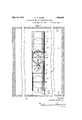
In the drawings, Fig. 1 is an elevational View of a device embodying my invention,
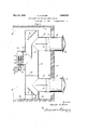
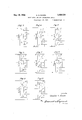
the same being illustrated as installed in a 3 chamber of a building structure; Fig. 2 is a longitudinal central sectional View of said device and Figs. 3 to 10 inclusive are diagrammatical views thereof.
In the drawings, I have shown a building structure comprising a Hoor 10, side walls 11, end walls 12 and a ceiling 13, which provide a chamber X. The Ventilating and air circulating device illustrated as installed -in said chamber includes an upright main pipe 14, the upper end of which falls short of the ceiling 13 of 'the chamber X, the lower end thereof being disposed `slightly above the iioor 10 of said chamber, Issuing horizontally from the upper portion of said main pipe 14 is an upper branch pipe 15, a thimble 16 being'fitted thereto and forming an extension thereof. Issuing horizontally from the lower portion of the main pipe 14 is a lower branch pipe 17 fitted with a thimble 18 forming an extension therefor. Said thim- 55 bles 16 and 1,8 extend through openings 19v and 20 in an en'd wall 12 of the building structure, each of said thimbles being provided at its outer end with a jack 21 of conventional design, Issuing horizontally from 60 the main pipe 14, substantially medially thereof, and in relation diametrically opposed to that of the upper and lower branch pipes 15 and 17 is an intermediate branch -pipe 22 over the end of which is fitted an ex- 65 tension sleeve 23. Mounted within said intermediate branch pipe 22 is a fan support 24,`
in which a fan 25 is revolubly mounted. Ab motor 26, suspended beneath the sleeve 23, drives said fan 2'5 through a belt 27 reaching 70 froma pulley 28 on the motor shaft 29 to a pulley. 30 on the fan shaft-31.. The motor 26 is of the reversible type, but ordinarily in the use of my invention, rotates to revolve the fan 25 in a direction to draw air from 75 the main pipe 14 and force it outwardly into the interior of the chamber X.
The upper and lower branch pipes 15 and ,17 are respectively fitted with dampers 32 `and 33. Within the main pipe 14 and above 80 the junction therewith of the upper branch pipe 15 is a damper 34. Also within said mail` pipe 14 and beneath the junction therewith of the lower branch pipe 17 is a dam er 35. Also within said main pipe 14 and e- 85 tween the junctions therewith 'of the 'upper branch pipe 15 and the intermediate branch pipe 22 is a damper 36. And, further, within said main pipe 14 and between the Ijunctions therewith of the intermediate branch pipe 22 and the lower branch pipe 17 is a damper 37 all of said dampers 32, 33, 34, 35,
36 and 37 having operating handles therefor accessible from one side of the device.'
Supporting the main pipe 14 vare a number .95 of legs 38 which are secured at their upper nds to the lower marginal portion of said pipe and which are formed at their lower ends with feet 39 having their footing on the floor 10 of the chamber X. f 10 ber medially longitudinally ythereof in space which is ordinarily free from obstructions and which, in storage rooms, is ordinarily u seldas a central 'tru'cking passageway or ais e. l A v \Any of numerous results may be secured 'i in the operation of my improved device, some tion. f
therefrom by the fan 25.
- be closed. The remaining properly would be fully and Eartially opened, j
i Fig. 5,
of the principal uses thereof bein illustrated in the diagrammatical figures of t e drawings numbered 3 to 10 inclusive. In. illustrating' the various damper adjustments in these various views, I have shown in each instance only such of the dampers as necessarily must dampers, which ave been omitted to sim fy theillustra- With the dampers adjusted as shown in Fig. 3, the device serves as a recirculator, the air being drawn into the main pipe 14 at the upper portion of the chamber and expelled Under the adjustment o f valves shown in Fig. 4, the devic also serves as a recirculator, theair' iii this instance being drawn into the main pipe 1 4 from the lower portion of the chamber. This latt'er `adustment of valves (Fig. 4) may be preferre over the adjustment ZFig. 3) rst noted, under conditions where it is advisable to take into the main pipe 14 the relatively cold dry air from the iioor rather than the relatively warm humid air at the ceilin But, in instances where there is no suc choice,.both of the dampers 36 and 37 may be left open in the air recirculating process.
In adjusting the dampers as indicated in the chamber is ventilated, the coldest driest air being exhausted from the chamber at the lower portion thereof. In the event that it is .colder within thefchamber than without, gravity assists in the forced ventilating process and, if desired, the fan 25 may be stoppe'd andthe ventilation carried on by gravity alone. Q
In Fig. 6, the indicated adjustment of y 4 dampers provides for forced ventilation, the warmest and most humid air being exhausted from the upper portion of the chamber. In case it is warmer inside than outside, the fan 25 is assisted b gravity in carrying on ventilation and, if dsasired, the fan may e stopped and ventilation eifected by gravity alone.
i Ventilation and recirculationV combined is carried on with an adjustment ofthe dampers junction therewith of as illustrated in Figs. 7 and 8, the air, in the I first instance, being exhausted from the iioor of the chamber and, in the second instance, being exhausted from the ceiling thereof.
With an adjustment of the dampers, as indicated in Fig. 9, fresh air is forced into the chamber and the internal pressure built up. This condition, in some cases, is desired, ventilation being accomplished through the eX- haustion of air `from the chamber by leakage. With the dampers set as indicated in Fig. 10 and the fan stopped, and with the temperature inside of the chamber higher than that outside thereof, ventilation is eifected by gravity alone, the air in such case being exhausted from the chamber proper through the intermediate branch pipe 22. In thus taking the air from intermediate strata, as'
distinguished from the upper stratay at the ceiling, the relative percentage of humidity in the air within the chamber is conserved.
Changes in the specific form of my invention, as herein disclosed, may be made within the scope of what is claimed' without departing from the spirit of my invention.
Having described my invention, what I claim as new and desire to protect by Letters Patent is:
I claim`: i
1. In combination with a structure forming a chamber, a main pipe disposed in upright position therein and communicating at its upper end with the upper portion of lthe chamber and at its lower end with the lower portion of said chamber, legs supporting -said main pipe, an upper branch pipe issuing from the upper portion of the main pipe through a wall of said structure and communicating with the outer atmosphere, a damper'in said upper branch pipe, a lower branch pipe issuing from the lower' portion of said main pipe through a wall of said structure and communicating with the outer atmosphere, a damper in said lower branch pipe, said branch pipes serving to steady said main pipe, an intermediate branch pipe issuing from the main pipe between the levels of said upper and lower branch pipes and communicating with the interior of the 'chamberf a y fan within said intermediate branch pipe adapted to draw air from the main pipe and force it into the interior of the chamber, a motor mounted on the intermediate branch lpipe for driving said fan,
a damper disposed in the main pipe between the upper end thereof and the junction therewith of the upper branch pipe, another damper disposed in the main pipe between the lower end thereof and the junction thereioo with of the lower branch pipe, another damper disposed in said main pipe between the the upper and intermediate branch pipes, and another damper disposed in said pipe between the junctions therewith of said intermediate branch pipe and the lower branch pipe.
.2. In combination with a structure forming a chamber, a main pipe disposed in upright position therein and communicating at its upper end with the upper portion of the chamber and at its lower end with the lower portion of said chamber, an upper branch pipe issuing from the upper portion of the main pipe through a wall of said structure and communicating with atmosphere outside of said chamber, a damper in said upper branch pipe, a lower branch pipe issuing from the lower portion of said main pipe through a wall of said structure and communicating with atmosphere outside of said chamber, a damper in said lower branch pipe, an intermediate branch pipe issuing from the main pipe between. the levels of said upper and lower branch pipes and communieating with the interior of the chamber, a fan within said intermediate branch pipe adapted to draw air from the main pipe and force it into the interior ofthe chamber, a damper disposed in the main pipe between the upper end thereof and the junction therewith of the upper branch pipe, another damper disposed in the main pipe between the lower end thereof and the junction therewith of the lower branch pipe, another damper disposed in said main pipe between the junctions therewith of the upper and intermediate branch pipes and another damper disposed in said pipe between the junctions therewith of said intermediate branch pipe and the lower branch pipe.
3. In combination with a structure forming a chamber, a main pipe Adisposed in upright position therein and communicating at its upper end with the upper portion of the Chamberland at its lower end'with the lower portion of said chamber, an upper branch pipe issuing from the upper portion of the main pipe and communicating with the outer atmosphere, a lower branch pipe issuing from the lower portion of said main pipe and communicatin with the outer atmosphere, a damper disposed in the main pipe between the upper end thereof and the j unction therewith of the upper branch pipe, a second damper disposed in the main ipe between the lower end thereof and the junction therewith of the lower branch pipe, a third damper disposed in said main pipe beneath the junction therewith of the upper branch pipe, and a fourth damper disposed in said v pipe above the junction therewith of said. lower-branchl pipe, said main 'pipe having an j opening therein bringing the same into communication with the interior of the chamber at a point between said third and 'fourth dampers. i 1
4. In combination with a structure-forming a chamber, a main pipe disposed .in ppright position therein and communicating at its .upper end with the` upper portion of the chamber and at its lower end with the lower portion of said chamber, an upper branch pipe issuing from the upper portion of the main pipe and communicating with the outer atmosphere, a lower branch pipe issuingfrom the lower portion of said ma'in pipe and communicating with the outer atmosphere, a damper disposed in the main pipe between the upper end thereof and the junction therewith of the upper branch pipe, a second damper disposed in the main pipe between the lower end thereof and the junction therewith of the lower branch pipe, a third damper disposed in said main pipe beneath the junction therewith of the upper branch pipe, and a fourth damper disposed in said pipe above the junction therewith of said lower branch pipe, said main pipe having an opening therein bringing the saine into communication withthe interior of the chamber at a, point between said third and fourth dampers, and a fan for impelling air from said main pipe, through said opening, into said chamber. Y
5. In combination with a structure forming a` chamber, a main pipe disposed in upl ymediate branch pipe issuing from the mainA pipe between the levels of said upper and lower branch pipes andcommunicating with the interior of the chamber, a fan' within said intermediate branch pipe ada ted to draw air from the main pipe and o rce it into the interior of the chamber, andmeans` for selectively obstructing `"the `passageway within said main lpipe between the junctions therewith of the upper and intermediate branch pipes and between the junctions thereiis with Aof said intermediate branch pipe and the lower branch pipe. j
6. In combination with a structure forming a chamber a main pipe disposed in klipright positiont chamber and at its lower end with the lower portion of said chamber, an upper branch pipe issuing from the upper portion of the main pipe through a wall 'of said structure and communicating with the outside atmosphere, a lower branch pipe. issuing from the lower ortion of said main pipe through a wall o said structure and communicating herein andy communicating atu its' upper Iend with Vthe -upper portion of theA `with the outside atmosphere, an intermediate branch tpipe issuing from the main pipe between the levels of said upper and lower branch pipes and communicatin interior of the chamber, a fan wi said intermediate branch pipe adapted to draw air chamber and 'at its lower end with'the lower' fiportion of' said chamber, an upper branch 1. pipe issuing from the upper portion of the main pipe and communicating with the outer atmosphere, a lower branch pipe issuing from the lower portion of said main pipe and comlis' municating with the outer atmosphere, said main pipe having an opening therein bringing the saine' i to communication with the interior of the chamber at an elevation between the junctions of said main pipe with $6 said upper and lower branch pipes, an m ans for obstructing the passageway within said main pipe between said opening and one of said branch ipes. I y 8'. In com ination with a structure rfermin achamber, amain pipe disposed in uprg t. ition therein and communicating at its upper end'fwith the upper portion of the chamber and at its lower'end with the lower portion of said chamber,`an upper branch inain' pipe and communicating with the outer .atmosphere,a lower branch pipe issuing from A@lower portion of said main'pipe and comunicatin'g with'th'e outer atmosphere, said v in pipe -havingan opening therein bringingt-he same into communication with the interior of the chamber at an elevation between the' junctions of said main'pipe with said `upl per and lower branch pipes, and means for obstructing the :passageway within said main pipe betweeny said openingand one of said ranch pipes, and means forobstructing said passa way between thel other branch pipe and t e adjacent end of@ said main pipe.
ing a chamber, a main .pipej disposed in upits upper end with the upper portion of the chamber and at its lower end with the lower portion of said chamber,'an upper branch pipe yfroniithe upper portion of the rl`main pipe an `communicating with the outer atmosphere, a lower branch pipe issuin from l the lower portion of said main pipe an com- 3j' municating with theA outer atmosphere,- said with the ppeissuing from the upper .portion of the' 9. In combination witha structure formmain pipe having an opening therein bringing the same into communicationwith the inatmosphere, a second branch pipe 'issuing from said main pipeat a lower elevation than said {irst branch pipe and also communicating with the outer atmosphere, said main pipe having an opening therein bringing the same into communication, with the interior of the chamber at an elevation above the junction between said `inain ipe and said second branch pipe, a fan or impelling air from saidxmain pipe through said opening, and means for obstructing the passagewaywithin said` main pipe at an elevation above the junctionbetween said main pipe and said second branch pipe, but beneath said o ening and beneath the junction between sai main pipe and'l said first branch pipe.
11. In combination with a structure-'form- Y ing a chamber, a main'pipe disposed in upright position therein and c'mmuni'cating at 'its upper and lower-ends with the interior of the chambei ..al branch pipe issuing from ,the main pi "and commumcating with the outer atingsp ere, means for obstructing the passageway in said branch pipe, a second branch lpipe issuing from said main ipe at a lower elevation than said first branc pipe and also commumcatingl with the (puter atmosphere, means for obstructing the passageway inl said second branch pi said main pipe having an opening therein ringing the same into communication with the interior of the -chamber at an elevation above the junction between said main pipe and said second branch pipe, a fan for im lling air from said main pipe through sai opening, and means for obstructing the passageway within said main Apipe at an elevation above the junction between said main lpipe and said second branch pipe, but beneat said opening and beneath the vjunction, between said main pipe and said `first branch pipe. right position therein and communicating at i j 12. In combination with a structure forming a chamber, afmain pipe disposed in upright position therein and communicating at its uplper and lower endsl with the interior of the c amber,a branch pipe issuing from the main pipe and communicating wit the outer atmosphere, a second branch v'pipe issuing lfrom said main pipe ata lower elevation than said 'first branch pipe and also comlng the same into communication Awith the interior of the chamber at an elevation be-` '5f neath the junction between said main pipe and said -irst branch pipe, a fan for impelling air from said mainpipe through said opening, and means for obstructing the passageway within said main pipe at an elevation beneath the junction between said main pipe f and said first branch pipe, but above said opening and above the junction between said main pipe and said second branch pipe.
13. In combination with a structure forming a chamber, a main pipe disposed in upright position therein and communicating at its upper and lower ends with the interior of the chamber, a branch pipe issuing from the main pipe and communicating with the outer atmosphere, means for obstructing the passageway in said branch pipe, a second branch pipe issuing from said main pipe at a lower elevation than said first branch pipe and also communicating with the outer atmosphere, means for obstructing the passageway Xin said branch pipe, said main pipe having an opening therein bringing the same into communication with the interior of the chamber at an elevation beneath the junction between said main pipe and said first branch pipe,
a fan for impelling air from said main pipe through said opening, and means for obpipe at an elevation beneath the junction between said main pipe and said rst branch pipe, but above said opening and` above the junction between said main pipe and said second branch pipe.
14. In combination with a structure forming a chamber, a main pipe disposed in upright position therein and communicating at its upper and lower ends with the interior of the chamber, a branch pipe issuing from the main pipe and communicating with the outer atmosphere, a second branch pipe issuing from said main pipe at a lower elevation than y said irst branch pipe and also communicating with the outer atmosphere,l said main pipe having an opening therein between its ends and communicating with the interior of the chamber through said opening, a fan for impelling air from said main pipe through said opening. andmeans for obstructing the passageway in said main pipe at various to said opening and to the junctions between said main pipe and said branch pipes.
15. In combination with a structure forming a chamber, a vmain pipe disposed in upright position therein and communicating at `its upper and lower ends with the interior of the chamber, a branch pipe issuing from the main pipe and communicating with the outer atmosphere. means for `ob tructing the pas- 1 sageway within said branch'pipe, a second structing the passageway within said mainI points relative to the open ends thereof and Y branch pipe issuing from said main pipe at a lower elevation than said first branch pipe and also communicating with the outer at# mosphere, means for obstructing the passageway within said second branch ipe, said main pipe having an opening therem between its ends and communicating with the interior of the chamber through said opening, a fan for impelling air from said main pi e through said opening, and means for o structing the passageway in said main pipe at various points relative to the open ends thereof and to said opening and to the junctions between said main pipe and said branch pipes, whereby the controlled ventilation of the chamber may be effected concurrently with the recirculation of air within the room in selective circulatory directions.
In testimony whereof I have aixed my signature. l
CHARLES A. MOORE.
Priority Applications (1)
| Application Number | Priority Date | Filing Date | Title |
|---|---|---|---|
| US482632A US1858024A (en) | 1930-09-17 | 1930-09-17 | Ventilating and air circulating device |
Applications Claiming Priority (1)
| Application Number | Priority Date | Filing Date | Title |
|---|---|---|---|
| US482632A US1858024A (en) | 1930-09-17 | 1930-09-17 | Ventilating and air circulating device |
Publications (1)
| Publication Number | Publication Date |
|---|---|
| US1858024A true US1858024A (en) | 1932-05-10 |
Family
ID=23916810
Family Applications (1)
| Application Number | Title | Priority Date | Filing Date |
|---|---|---|---|
| US482632A Expired - Lifetime US1858024A (en) | 1930-09-17 | 1930-09-17 | Ventilating and air circulating device |
Country Status (1)
| Country | Link |
|---|---|
| US (1) | US1858024A (en) |
Cited By (7)
| Publication number | Priority date | Publication date | Assignee | Title |
|---|---|---|---|---|
| US2635524A (en) * | 1949-04-04 | 1953-04-21 | Ralph D Jenkins | Air circulating or ventilating unit |
| US2896061A (en) * | 1958-03-27 | 1959-07-21 | Alice A Mcmillan | Air rinse |
| US3691929A (en) * | 1971-03-16 | 1972-09-19 | Laminated Wood Products Co | Air control system |
| US4738188A (en) * | 1984-02-25 | 1988-04-19 | Nishida Tekko Corporation | Room air circulating apparatus |
| US4905578A (en) * | 1989-01-03 | 1990-03-06 | Curtis Michael S | Apparatus for ventilating controlled areas |
| US5031515A (en) * | 1988-02-18 | 1991-07-16 | Halton Oy | Method for regulation of ventilation as well as an air-conditioning device used in the method |
| US5464370A (en) * | 1992-09-21 | 1995-11-07 | Yugen Kaisha New Media Systems | Device for changing a fluid passage |
-
1930
- 1930-09-17 US US482632A patent/US1858024A/en not_active Expired - Lifetime
Cited By (7)
| Publication number | Priority date | Publication date | Assignee | Title |
|---|---|---|---|---|
| US2635524A (en) * | 1949-04-04 | 1953-04-21 | Ralph D Jenkins | Air circulating or ventilating unit |
| US2896061A (en) * | 1958-03-27 | 1959-07-21 | Alice A Mcmillan | Air rinse |
| US3691929A (en) * | 1971-03-16 | 1972-09-19 | Laminated Wood Products Co | Air control system |
| US4738188A (en) * | 1984-02-25 | 1988-04-19 | Nishida Tekko Corporation | Room air circulating apparatus |
| US5031515A (en) * | 1988-02-18 | 1991-07-16 | Halton Oy | Method for regulation of ventilation as well as an air-conditioning device used in the method |
| US4905578A (en) * | 1989-01-03 | 1990-03-06 | Curtis Michael S | Apparatus for ventilating controlled areas |
| US5464370A (en) * | 1992-09-21 | 1995-11-07 | Yugen Kaisha New Media Systems | Device for changing a fluid passage |
Similar Documents
| Publication | Publication Date | Title |
|---|---|---|
| US2210458A (en) | Method of and apparatus for air conditioning | |
| US4334577A (en) | Ventilating system for livestock houses | |
| US1858024A (en) | Ventilating and air circulating device | |
| EP0713060A4 (en) | Water supply device for humidification and air conditioner with the same | |
| DE19710072C2 (en) | Rod system or hose system for the sanitary or care sector | |
| US2188566A (en) | Air conditioning system for buildings | |
| US1887938A (en) | Nozzle heating, cooling and ventilating system | |
| US1615964A (en) | Ventilating device for farm buildings | |
| US2419806A (en) | Inlet and outlet air distributing duct for buildings having automatic damper means | |
| CN205882421U (en) | Waterproof distribution box | |
| US1773220A (en) | Heating, ventilating, and cooling system | |
| DE2953055A1 (en) | Radiant heating system using partitioned lighting plenums | |
| US1542178A (en) | Ventilating system | |
| US2154410A (en) | Ventilating apparatus | |
| US1375417A (en) | Sleeping-compartment | |
| US2224878A (en) | Air cooling and circulating device | |
| US1706893A (en) | Cavity-wall hot and cool-air circulation | |
| US1911602A (en) | Lillian brandl executrix of said | |
| US2722169A (en) | Selective air circulating and cooling system | |
| US1731432A (en) | Air-conditioning appliance | |
| Turnbull | Housing and environment for dairy calves | |
| JPS5520339A (en) | Ventilating and cooling method of room | |
| US2333556A (en) | Insulating and air-conditioned building construction | |
| US186053A (en) | Improvement in ventilating halls | |
| US2511139A (en) | Electric air circulating heater |