US1857742A - Picture telegraphy circuit - Google Patents
Picture telegraphy circuit Download PDFInfo
- Publication number
- US1857742A US1857742A US487118A US48711830A US1857742A US 1857742 A US1857742 A US 1857742A US 487118 A US487118 A US 487118A US 48711830 A US48711830 A US 48711830A US 1857742 A US1857742 A US 1857742A
- Authority
- US
- United States
- Prior art keywords
- relay
- synchronizing
- drum
- circuit
- stop
- Prior art date
- Legal status (The legal status is an assumption and is not a legal conclusion. Google has not performed a legal analysis and makes no representation as to the accuracy of the status listed.)
- Expired - Lifetime
Links
Images
Classifications
-
- H—ELECTRICITY
- H04—ELECTRIC COMMUNICATION TECHNIQUE
- H04N—PICTORIAL COMMUNICATION, e.g. TELEVISION
- H04N1/00—Scanning, transmission or reproduction of documents or the like, e.g. facsimile transmission; Details thereof
- H04N1/32—Circuits or arrangements for control or supervision between transmitter and receiver or between image input and image output device, e.g. between a still-image camera and its memory or between a still-image camera and a printer device
- H04N1/36—Circuits or arrangements for control or supervision between transmitter and receiver or between image input and image output device, e.g. between a still-image camera and its memory or between a still-image camera and a printer device for synchronising or phasing transmitter and receiver
Definitions
- the invention relates to a circuit arrangement for apparatusfor use in picture telegraphy systems or the like which are provided with devices for the start-stop type of synchronizing.
- a number of the transmitters as well as the receivers may be operated from alternating current supply lines and equipped with synchronous motors and other parts of the system may be operated from D. C. supply lines and equipped with D. C. motors.
- the only stipulation is that from each and any receiver a connection may be established with each transmitter with the result that there appear the following five possibilities of combination: 1. Assume a case where the transmitte system is provided with a synchronous motor for driving the picture apparatus. Then (a) The receiver also may be provided with a synchronous motor which is connected to the same supply network as the transmitting motor; I
- the receiver may also be provided with a synchronous motor but this motor may be connected in a supply network different from the transmitting motor network; and, (c) The receiver may be provided with a D. C. motor.
- the transmitter sys-' tem is provided with a D. C. motor for driving the 'icture apparatus.
- he receiver may be provided with a synchronous motor for driving the receiver apparatus;
- the receiver apparatus may also be provided with a D. C. motor.
- start-stop synchronizing methods may be used, but in the case 1a, however, start-stop synchronization would disturb the already existing synchronism, for the reason that the receiving drum would then participate only in each second revolution of the transmitting drum because ithas no lead relative to the transmitting drum so that the synchronizing marks could not be effective Hence, the start-stop.
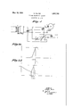
- Fig. 1 shows one form of the circuit and system according to the disclosure.
- Figs. 2a and 2b are curves illustrating the operation of the system of Fig. 1.
- the current source 2 for the local circuit is represented conventionally as a rectifier which is supplied with energy from an A. C. supply line and whose output. is connected in parallel with a condenser 3.
- Numeral 8 represents the picture drum or, where desired, a disk rigidly connected with the picture drum.
- the drum 8 is provided with a groove or slot on the circumference which may be engaged by the ratchet pawl 7 of the ratchet relay 1.
- the ratchet relay 1 may receive current via two different ways; in the first place by means of the synchronizing signals coming from the transmitter which signals reverse the synchronizing relay 4, set for one side, from the the impulses released by the synchronizing signals, is adjusted with the aid of resistance 11 in such a manner that it is located as close- 1y as possible under the responding current of the ratchet relay 1.
- the arrangement When using non-synchronous motors the arrangement operates according to the well -known start-stop principle:
- the receiving drum receives relative to the transmitting drum a suitably calculated lead so that the ratchet pawl 7 engages the groove always prior to the arrival of the synchronizing signal.
- the synchronizing signal closes, by the reversal of the relay 4 from contact 9 to contact 5, the circuit of the ratchet relay withthe result that the drum is released again.
- By-means of the condenser 3 there is caused in the known manner an acceleration of the switching-in action.
- the ratchet relay is provided with some means or other which cause a retarded fading out of the magnetic field, which has been graphically represented by Fig. 26; this may for instance take place by means of a number of short-circuit windings wherein there is generated by the switching-out impulse an induction impulse which still maintains the magnetic field for a certain length of time.
- the receiving drum is automatically stopped and is disposed in the position necessary for the next operation of the phase-correct coupling system to reproduce another picture subject.
- a record drum having a slot in one end thereof, a start-stop relay system having an armature adapted to rest in said slot at predetermined time intervals, means for continually supplying current of predetermined strength to said start-stop relay, a capacity element shunting said current supply and adapted to be charged during theperiods between successive operations of said start-stop relay, and a synchronizing relay responsive to received synchronizing impulses coordinated with said start-stop relay for causing a discharge of the energy stored in said capacity element and thereby producing an operation of said start-stop relay armature so as to disengage the armature from the slot in said record carrying drum.
- a start-stop relay system having an armature adapted to normally rest in a slot on the record receiving drum, means for continually passing current of a strength slightly less than that required for operation of said start-stop relay through said relay, an electrical storing element connected across said current supply, a synchronizing relay cooperating with said start-stop relay,
- a synchronizing relay responsive to incoming synchronizing signal impulses for produclng an operation of said synchronizing relay whereby said storing element is discharged and the tween the receipt of synchronizing signalling impulses, a synchronizing relay cooperating with said start-stop relay and having its armature connected with the winding of said start-stop relay, a resistor for regulating the current flow through said start-stop relay during periods between the receipt of synchronizing signalling impulses upon said synchronizing relay, 2.
Landscapes
- Engineering & Computer Science (AREA)
- Multimedia (AREA)
- Signal Processing (AREA)
- Synchronisation In Digital Transmission Systems (AREA)
Applications Claiming Priority (1)
| Application Number | Priority Date | Filing Date | Title |
|---|---|---|---|
| DES93632D DE515045C (de) | 1929-08-29 | 1929-08-30 | Schaltungsanordnung fuer Bildtelegraphenapparate o. dgl., die mit Vorrichtungen zur Start-Stop-Synchronisierung ausgeruestet sind |
Publications (1)
| Publication Number | Publication Date |
|---|---|
| US1857742A true US1857742A (en) | 1932-05-10 |
Family
ID=32978976
Family Applications (1)
| Application Number | Title | Priority Date | Filing Date |
|---|---|---|---|
| US487118A Expired - Lifetime US1857742A (en) | 1929-08-30 | 1930-10-08 | Picture telegraphy circuit |
Country Status (2)
| Country | Link |
|---|---|
| US (1) | US1857742A (fr) |
| FR (1) | FR701192A (fr) |
-
1930
- 1930-08-20 FR FR701192D patent/FR701192A/fr not_active Expired
- 1930-10-08 US US487118A patent/US1857742A/en not_active Expired - Lifetime
Also Published As
| Publication number | Publication date |
|---|---|
| FR701192A (fr) | 1931-03-12 |
Similar Documents
| Publication | Publication Date | Title |
|---|---|---|
| US2207720A (en) | Communication system | |
| US1857742A (en) | Picture telegraphy circuit | |
| US1970455A (en) | Electric selector | |
| US2344231A (en) | Remote control and supervisory system | |
| US1888904A (en) | Station calling device | |
| US2411441A (en) | Telegraph receiving distributor system | |
| US2506437A (en) | Combined voice and facsimile system | |
| US3336445A (en) | Holding system for general automatic telephone circuit | |
| US2626987A (en) | Automatic switching system for electrical telecommunications | |
| US2101224A (en) | Privacy system | |
| US1874664A (en) | Multiplex telegraphy | |
| US2154623A (en) | Regenerative telegraph repeater | |
| US1717116A (en) | Correcting circuit for ocean-cable relays | |
| US1616326A (en) | Telegraph system | |
| US1601941A (en) | Submarine telegraph system | |
| US2870246A (en) | Two way facsimile repeater | |
| US2453773A (en) | Diplex transmission by combined frequency-amplitude modulation | |
| US2874218A (en) | Phasing system | |
| US1934364A (en) | Impulse receiving system | |
| US2546369A (en) | Start-stop repeater | |
| US2086638A (en) | Regenerative telegraph repeater | |
| US1501683A (en) | Remote control system | |
| US2220889A (en) | Communication system | |
| US1717049A (en) | Synchronous telegraph system | |
| US1617993A (en) | Multiplex-channel repeater system |