US1857737A - Flat hosiery knitting machine - Google Patents
Flat hosiery knitting machine Download PDFInfo
- Publication number
- US1857737A US1857737A US401851A US40185129A US1857737A US 1857737 A US1857737 A US 1857737A US 401851 A US401851 A US 401851A US 40185129 A US40185129 A US 40185129A US 1857737 A US1857737 A US 1857737A
- Authority
- US
- United States
- Prior art keywords
- sinkers
- rails
- knitting machine
- guides
- guide
- Prior art date
- Legal status (The legal status is an assumption and is not a legal conclusion. Google has not performed a legal analysis and makes no representation as to the accuracy of the status listed.)
- Expired - Lifetime
Links
- 238000009940 knitting Methods 0.000 title description 6
- 238000010276 construction Methods 0.000 description 3
- 210000001331 nose Anatomy 0.000 description 3
- 230000007246 mechanism Effects 0.000 description 2
- 229920000742 Cotton Polymers 0.000 description 1
- 241000448280 Elates Species 0.000 description 1
- 230000000881 depressing effect Effects 0.000 description 1
- 230000000994 depressogenic effect Effects 0.000 description 1
- 238000006073 displacement reaction Methods 0.000 description 1
- 239000004744 fabric Substances 0.000 description 1
- 229920000136 polysorbate Polymers 0.000 description 1
Images

Classifications
-
- D—TEXTILES; PAPER
- D04—BRAIDING; LACE-MAKING; KNITTING; TRIMMINGS; NON-WOVEN FABRICS
- D04B—KNITTING
- D04B11/00—Straight-bar knitting machines with fixed needles
Definitions
- This machine has therefore not been capable of producing a regular plush fabric.
- the sinkers for V sinking the plush loops are provided with al- 80 most horizontally extending noses.
- the tubular guide for the base thread in this construction stands so low between the sinker plates, that the thread is laid properly in the lower throat of the same. No dilficulties are encountered here in knocking over, as in the first described machine. But this second machine is not suitable for producing narrowed goods either, because the tube, which lay the base thread, then comes to rest each time be- 80 tween two sinkers and. stands in the way of the intermediate dividing sinkers.
- the base thread is laid by a special thread guide, which in itself is not new.
- the thread guide in looping the threads, stands low between the throat Elates, which is also old per se, but is raised, efore dividing, so high that the corresponding dividing sinker can make its movement unhindered. In this way it is possible, even in machines of the finest distribution, to let the base thread guide project between the sinkers during the sinking of the loops.
- the base thread guide 9 is lowered to between the sinkers, lays thread But since the upper, upwardly point- 401,851, and in Germany November 13, 1928.
- FIG. 6 is a front view of Fig. 1, and Figs. 7+11 are detail views of various mechanisms which candbe used to raise and lower the thread 15 1 e. 1
- the base thread guides 7, in number equal to that of the width sections, are mounted on rails 19, which slide in slots in the guide block 22. These slots are extended so far upwardly so that upward movement can be given to the rails '19 (Fig. 1). Since the rails 19 have in this we a certain amount of play in their. guide s ots, springs 24 are provided to hold them down.
- roller 15 of lever 16 runs upon the raised portion of the eccentric 14, so that the guides 7 extend down under the noses 10 of the plates 5, forming the lush loops, in order to lay the base, threads reely in the throats 8 (Fig. 2), and before the com- 'mon advance of the dividing sinkers 6, the portion 21 of the eccentric 14: comes under the ro1ler15, so that the guides 7 are raised 10o which the plush lining is also obliquely lpl ounded at the obliqueedges 4 of the goods, 1g. 5.
- covered plush goods comprising dividing slnkers, jack sinkers, which have special upper nibs, and base thread guides roing sinkers which move forward later and wherein the base thread guides are again depressed after the dividing and before the sinking of the loops, guide blocks and supporting rails for the base thread guides, said guide blocks having upwardly extending slots wherein said supporting rails are movable vertically.
- guideways 25 can be provided on the rails 19, as in Fig. 7, the same being of the necessaryrlength for the displacement of the rails.
- the movement of the bracket 22 with the thread guides is imparted by the rod 29, connected to the anglelever 30 and 31, and is correctly positioned by the same.
- the pivot 26 can also be on the other side of the bearing 22.
- the bracket 22 may be provided with guides or bushings 33, movable obliquely upwards, for the rails 19, said guides being controlled by a lever 18 in the manner described above.
- a fiat hosiery knitting machine for making covered plush goods comprising dividing sinkers, jack sinkers, which have special upper nibs, and base thread guides projecting into the jack sinkers which lay their threads into the lower nibs of the said sinkers, and means whereby the said guides for the base threads, which during the sinking of the loo s project into the jack sinkers, after
Landscapes
- Engineering & Computer Science (AREA)
- Textile Engineering (AREA)
- Knitting Machines (AREA)
Description
May 10, 1932 R. NEBICH v FLAT HQSIERY KNITTING MACHINE Filed Oct. 25, 1929 2 She e1;s-Shee't 1 May 10, 1932. R. NE BIC 7 1,857,737
v FLAT HOSIERY'KNITTING MACHINE Filed Oct. 25, 1929 2 Sheets-Sheet 2 Patented Ma 10, 1932 PATENT ormca BUDI NEIBICH, OI CEEMNITZ, GERMANY FLAT HOSI'EBY KNITTING MACHINE Application filed October 23,1929, Serial No Flat hose-knitting machines, for eziample, cotton machines for producing loop plush goods, are already known. It has also been attempted to produce narrowed plush goods on these machines. The usual double-throated sinkers, in one instance, were so made that their two nose ends lay in a horizontal plane. In this construction, the thread guides stood over the sinkers and regular work was possible. ingnose which sinks the plush loop, does not release the same to be knocked over, the loops are broken as the needle bars go down.
This machine has therefore not been capable of producing a regular plush fabric.
In another machine, which, however, apears to be'only adapted to produce goo s hounded by straight lines, the sinkers for V sinking the plush loops are provided with al- 80 most horizontally extending noses. The tubular guide for the base thread in this construction stands so low between the sinker plates, that the thread is laid properly in the lower throat of the same. No dilficulties are encountered here in knocking over, as in the first described machine. But this second machine is not suitable for producing narrowed goods either, because the tube, which lay the base thread, then comes to rest each time be- 80 tween two sinkers and. stands in the way of the intermediate dividing sinkers. It is a well-known fact that the tube, or the outlet end of a thread guide, can stand between two sinkers. The space, between a sinker and a dividing sinker, is not suflicient for this tube which must be large enough for the relatively thick base thread.
In the present machine, the base thread is laid by a special thread guide, which in itself is not new. The thread guide, in looping the threads, stands low between the throat Elates, which is also old per se, but is raised, efore dividing, so high that the corresponding dividing sinker can make its movement unhindered. In this way it is possible, even in machines of the finest distribution, to let the base thread guide project between the sinkers during the sinking of the loops. Before the sinking of each row, the base thread guide 9 is lowered to between the sinkers, lays thread But since the upper, upwardly point- 401,851, and in Germany November 13, 1928.
- in this position and is raised after the looping. In this way it is possible to produce completely shaped goods, provided with loop plush lining, on fixed edge machines.
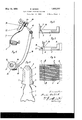
.Some embodiments of the invention are shown in the drawings, in which Fig. 1 is a side View showing a means for raising and lowering the base thread guide; Fig. 2 is a side view showing the position of the sinkerplate and of the thread guide before the 0 sinking; Fig. 3 is a similar vlew showing that, after the sinking, the base thread guide is raised so high that it is out of the way of I the dividing sinkers, passing by and shown in dotted lines; Fig. 4 is a plan of Fig, 3 and 5 shows the position of the base thread guide between the sinker plates looking from above, at the moment when t e same is raised out before the advance of the dividing sinkers; Fig. 5 shows an open stocking, which can be provided throughout with a loop plush lining by the present invention; Fig.
6 is a front view of Fig. 1, and Figs. 7+11 are detail views of various mechanisms which candbe used to raise and lower the thread 15 1 e. 1 The base thread guides 7, in number equal to that of the width sections, are mounted on rails 19, which slide in slots in the guide block 22. These slots are extended so far upwardly so that upward movement can be given to the rails '19 (Fig. 1). Since the rails 19 have in this we a certain amount of play in their. guide s ots, springs 24 are provided to hold them down. A lever 18, fast on a shaft 17, 5
engages under the rails 19, and this shaft is oscillated, for example, byan eccentric 14 on the main shaft 13, through the roller 15'and a lever 16, also fast on the shaft 17, so that the base thread guide 7 is raised and lowered by its rails 19.
In sinking the loops, roller 15 of lever 16 runs upon the raised portion of the eccentric 14, so that the guides 7 extend down under the noses 10 of the plates 5, forming the lush loops, in order to lay the base, threads reely in the throats 8 (Fig. 2), and before the com- 'mon advance of the dividing sinkers 6, the portion 21 of the eccentric 14: comes under the ro1ler15, so that the guides 7 are raised 10o which the plush lining is also obliquely lpl ounded at the obliqueedges 4 of the goods, 1g. 5.
.The construction described can be reversed 'by depressing the guides 7 and their rails 19 by the lever 18 into the position necessary for sinking the loops. In this case, lever 18 engages over the rails19 and the springs 24 are placed below the rails 19.
In order to assure an unhindered raising and lowering of the rails 19, it is advisable to permit the lever 18 to engage directly on said rails near the guide bearings 22, as in Flg. 6.
making covered plush goods comprising dividing slnkers, jack sinkers, which have special upper nibs, and base thread guides roing sinkers which move forward later and wherein the base thread guides are again depressed after the dividing and before the sinking of the loops, guide blocks and supporting rails for the base thread guides, said guide blocks having upwardly extending slots wherein said supporting rails are movable vertically.
In testimony whereof I have afiixed my signature.
RUDI NEBICII.
In some cases also, guideways 25 can be provided on the rails 19, as in Fig. 7, the same being of the necessaryrlength for the displacement of the rails.
If suflicient room exists below the rails 19, this mechanism can also be reversed, as in Fig. 8. It would also be possible, to pivot-the guide bracket 22 tothe machine frame at a point 26, so that it is drawn down by its own weight and by an elastic member, for example,
, a spring 27, and is correctly held in the upper position by an abutment 28. The movement of the bracket 22 with the thread guides is imparted by the rod 29, connected to the anglelever 30 and 31, and is correctly positioned by the same. The pivot 26 can also be on the other side of the bearing 22.
According to Figs. 10 and 11, the bracket 22 may be provided with guides or bushings 33, movable obliquely upwards, for the rails 19, said guides being controlled by a lever 18 in the manner described above.
Whether only one or several rails 19 are raised and lowered, is of no importance, nor is the number of the levers 18 used.
I claim:
1. A fiat hosiery knitting machine for making covered plush goods comprising dividing sinkers, jack sinkers, which have special upper nibs, and base thread guides projecting into the jack sinkers which lay their threads into the lower nibs of the said sinkers, and means whereby the said guides for the base threads, which during the sinking of the loo s project into the jack sinkers, after
Applications Claiming Priority (1)
| Application Number | Priority Date | Filing Date | Title |
|---|---|---|---|
| DE1857737X | 1928-11-13 |
Publications (1)
| Publication Number | Publication Date |
|---|---|
| US1857737A true US1857737A (en) | 1932-05-10 |
Family
ID=7746317
Family Applications (1)
| Application Number | Title | Priority Date | Filing Date |
|---|---|---|---|
| US401851A Expired - Lifetime US1857737A (en) | 1928-11-13 | 1929-10-23 | Flat hosiery knitting machine |
Country Status (1)
| Country | Link |
|---|---|
| US (1) | US1857737A (en) |
Cited By (4)
| Publication number | Priority date | Publication date | Assignee | Title |
|---|---|---|---|---|
| US2509032A (en) * | 1946-11-05 | 1950-05-23 | James L Buchanan | Knitting machine |
| US2528389A (en) * | 1949-03-08 | 1950-10-31 | Winborne W Saunders | Yarn carrier for knitting machines |
| US2602312A (en) * | 1950-05-08 | 1952-07-08 | Zimic | Yarn feed mechanism for knitting machines |
| US2670619A (en) * | 1949-12-28 | 1954-03-02 | Zimic | Yarn feed mechanism for knitting machines |
-
1929
- 1929-10-23 US US401851A patent/US1857737A/en not_active Expired - Lifetime
Cited By (4)
| Publication number | Priority date | Publication date | Assignee | Title |
|---|---|---|---|---|
| US2509032A (en) * | 1946-11-05 | 1950-05-23 | James L Buchanan | Knitting machine |
| US2528389A (en) * | 1949-03-08 | 1950-10-31 | Winborne W Saunders | Yarn carrier for knitting machines |
| US2670619A (en) * | 1949-12-28 | 1954-03-02 | Zimic | Yarn feed mechanism for knitting machines |
| US2602312A (en) * | 1950-05-08 | 1952-07-08 | Zimic | Yarn feed mechanism for knitting machines |
Similar Documents
| Publication | Publication Date | Title |
|---|---|---|
| US1857737A (en) | Flat hosiery knitting machine | |
| US2618444A (en) | Yarn tensioning | |
| US2143485A (en) | Yarn tensioning for knitting machines | |
| US2582465A (en) | Sinker cap and operating mechanism | |
| US2217520A (en) | Knitting machine | |
| US2056686A (en) | Production of knitted fabric | |
| US2126797A (en) | Knitting machine | |
| US2176911A (en) | Knitting machine | |
| US2187715A (en) | Method of and apparatus for knitting | |
| US2823528A (en) | Needle bar assembly and method of knitting | |
| US2030516A (en) | Jacquard pattern mechanism for knitting machines and method of patterning effected thereby | |
| GB425199A (en) | Improvements in or relating to knitting machines | |
| US2153582A (en) | Knitting machine | |
| US2032949A (en) | Flat knitting machine | |
| US2270361A (en) | Knitting machine | |
| US1797435A (en) | Knitting machine | |
| US1572993A (en) | Knitting machine | |
| US2317417A (en) | Knitting machine and method of knitting | |
| US2083394A (en) | Circular knitting machine and method of operating same | |
| US1998368A (en) | Method of and apparatus for casting on loops on flat knitting machines | |
| US2098739A (en) | Manufacture of full-fashioned hosiery on flat knitting machines | |
| US2142745A (en) | Mechanism for producing welts on straight bar knitting machines | |
| US2899811A (en) | Straight bar knitting machines | |
| US2192556A (en) | Flat knitting frame | |
| US2206808A (en) | Tubular elastic fabric and process of making same |