US1857725A - Roasting apparatus - Google Patents
Roasting apparatus Download PDFInfo
- Publication number
- US1857725A US1857725A US452382A US45238230A US1857725A US 1857725 A US1857725 A US 1857725A US 452382 A US452382 A US 452382A US 45238230 A US45238230 A US 45238230A US 1857725 A US1857725 A US 1857725A
- Authority
- US
- United States
- Prior art keywords
- roasting
- furnace
- pipe
- compartment
- compartments
- Prior art date
- Legal status (The legal status is an assumption and is not a legal conclusion. Google has not performed a legal analysis and makes no representation as to the accuracy of the status listed.)
- Expired - Lifetime
Links
- 239000007789 gas Substances 0.000 description 13
- 230000001105 regulatory effect Effects 0.000 description 9
- 239000000463 material Substances 0.000 description 7
- UCKMPCXJQFINFW-UHFFFAOYSA-N Sulphide Chemical compound [S-2] UCKMPCXJQFINFW-UHFFFAOYSA-N 0.000 description 6
- 150000003568 thioethers Chemical class 0.000 description 4
- 238000010276 construction Methods 0.000 description 3
- 238000001816 cooling Methods 0.000 description 3
- 238000004804 winding Methods 0.000 description 3
- XEEYBQQBJWHFJM-UHFFFAOYSA-N Iron Chemical compound [Fe] XEEYBQQBJWHFJM-UHFFFAOYSA-N 0.000 description 2
- 238000010438 heat treatment Methods 0.000 description 2
- 238000004140 cleaning Methods 0.000 description 1
- 150000001875 compounds Chemical class 0.000 description 1
- 239000000470 constituent Substances 0.000 description 1
- 230000008878 coupling Effects 0.000 description 1
- 238000010168 coupling process Methods 0.000 description 1
- 238000005859 coupling reaction Methods 0.000 description 1
- 230000003247 decreasing effect Effects 0.000 description 1
- 238000009826 distribution Methods 0.000 description 1
- 230000000694 effects Effects 0.000 description 1
- 238000005485 electric heating Methods 0.000 description 1
- 239000003546 flue gas Substances 0.000 description 1
- 238000003780 insertion Methods 0.000 description 1
- 230000037431 insertion Effects 0.000 description 1
- 229910052742 iron Inorganic materials 0.000 description 1
- 239000006148 magnetic separator Substances 0.000 description 1
- 238000000034 method Methods 0.000 description 1
- 230000000284 resting effect Effects 0.000 description 1
- 238000009827 uniform distribution Methods 0.000 description 1
Images

Classifications
-
- F—MECHANICAL ENGINEERING; LIGHTING; HEATING; WEAPONS; BLASTING
- F27—FURNACES; KILNS; OVENS; RETORTS
- F27B—FURNACES, KILNS, OVENS OR RETORTS IN GENERAL; OPEN SINTERING OR LIKE APPARATUS
- F27B3/00—Hearth-type furnaces, e.g. of reverberatory type; Electric arc furnaces ; Tank furnaces
- F27B3/10—Details, accessories or equipment, e.g. dust-collectors, specially adapted for hearth-type furnaces
- F27B3/22—Arrangements of air or gas supply devices
-
- F—MECHANICAL ENGINEERING; LIGHTING; HEATING; WEAPONS; BLASTING
- F27—FURNACES; KILNS; OVENS; RETORTS
- F27B—FURNACES, KILNS, OVENS OR RETORTS IN GENERAL; OPEN SINTERING OR LIKE APPARATUS
- F27B9/00—Furnaces through which the charge is moved mechanically, e.g. of tunnel type; Similar furnaces in which the charge moves by gravity
- F27B9/14—Furnaces through which the charge is moved mechanically, e.g. of tunnel type; Similar furnaces in which the charge moves by gravity characterised by the path of the charge during treatment; characterised by the means by which the charge is moved during treatment
- F27B9/20—Furnaces through which the charge is moved mechanically, e.g. of tunnel type; Similar furnaces in which the charge moves by gravity characterised by the path of the charge during treatment; characterised by the means by which the charge is moved during treatment the charge moving in a substantially straight path
- F27B9/24—Furnaces through which the charge is moved mechanically, e.g. of tunnel type; Similar furnaces in which the charge moves by gravity characterised by the path of the charge during treatment; characterised by the means by which the charge is moved during treatment the charge moving in a substantially straight path being carried by a conveyor
Definitions
- the present invention relates to a furnace for roasting sulphide ores.
- the furnace is particularly adapted for roasting sulphides of iron in order to convert them into magnetic compounds which subsequently may be separated from the still nonmagnetic valuable constituents of the material in a magnetic separator.
- the furnace may however be used generally for the roasting of sulphides.
- the accompanying drawings illustratepartly diagrammaticallythe construction of the furnace and its manner of working.
- the furnace is of the known shelf construction, but on account of several particular devices it represents a novel type of shelf burner.
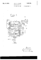
- Fig. 1 is a vertical section of the furnace.
- Figs. 2 and 3 show horizontal sections along the lines II-II and III-III of 1.
- the furnace is built up of cylindrical shelf compartments 1 with hollow bottoms 2.
- the furnace has three shelves but may of course be built up of any desired number of shelves.
- the lowermost bottom is supported by a frame 3, and the uppermost compartment carries a cover l, which is connected to the frame 3 by means of four rods 5.
- a vertical revolving shaft 6 is provided, the lower end of which rests on a lever 7.
- the middle portion of the shaft is of square section, while the ends are cylindrical.
- the shaft carries a worm-wheel 8, having a sleeveshaped hub, which is capable of being turned in a stationary bearing 9.
- the worm-wheel is driven in the direction of the arrow 1.0 from a horizontal worm shaft, not shown in the drawings.
- the worm-wheel 8 is connected to the shaft 6 by means of slot and key in such a manner, that the shaft rotates with the worm-wheel, but may be displaced axially relatively to the latter by moving the lever 7 upwards or downwards.
- a feeding device (not shown) the ore to be roasted is supplied to the top shelf of the furnace through four openings 11 in the top cover 4 near the centre pot the latter and is distributed by means of a spiral-shaped rab- 50 bling device 12.
- This rabbling device is provided with a quadrangular hub surrounding the shaft 6 with slight clearance so th 6 the rabbling device is resting on the botto/ p ate 2 and is moved from the shaft without being supported by it.
- the shaft carries a ring 13, which norinall is not in touch with the hub, but when tie shaft is raised as mentioned above by means of the lever 7 this ring 13 presses against the hub, which together with the rabbling device is displaced upwards. If the lever 7 is released or is moved quickly downwards, the rabbling device will by its own weight fall down upon the bottom 2 and suffers thereby vibrations. Such shaking of the rabbling device may be used from time to time according to the nature of the ore under treatment in order to free the device from material adhering thereto. The distance between the spiral windings of the device is decreasing from the centre towards the periphery, and the windings are stiffened by means of strips 14 across their upper edges.
- the bottom 2 is provided with four openings 15 at the periphery, through which the material falls down into the next compartment.
- a spiral-shaped rabbling device 16 is provided in which the windings are of opposite direction of that of the spiral 12 so that in this compartment the material is conveyed towards the centre, from where it falls down into the lowermost compartment through four openings 17.
- a spiral device 18 of like construction as that in the uppermost compartment conveys the material towards the pe riphery.
- the material leaves the furnace through an opening 19 in the lowermost bottom 2.
- the rabbling devices 16 and 18 are arranged just as the rabbling device 12 and may be raised by means of rings 13 fixed on the shaft 6 when the latter is displaced upwards.
- thermocouple 23 is provided for control of the temperature.
- the necessary air for carrying out the process is supplied under pressure through a measuring apparatus (not shown) from a main pipe 24, which by branch pipes 25 communicates with the several roasting compartments; In each branch pipe a regulating valve 26 is inserted.
- the openings 15 and 17 in the bottoms 2 are of such dimensions that air and gas freely and without hindrance from the ore may pass through the whole furnace.
- the gases leave each roasting compartment through pipes 27 with regulating valves 28 and a common main flue 29.
- the pipes 27 are made easily detachable by insertion of two couplings 30.
- a shut-0d valve 31 for use when the pipes are disengaged.
- the gas flue 29 ex tends into a sleeve of a curved pipe 33, through which the gases pass into a separate chamber of which only one wall 34 is shown in the drawings.
- the short pipe 33 is able to be turned in the wall 3i, for which pur pose a lever 35 may serve, which is mounted on the sleeve 32. Thereby this sleeve is turned about the end of the pipe 29.
- the flue gases will continue through the stationary flue 36, which leads to a fan.
- the draught in the flue 29 may be regulated. If for instance the pipe 33 is brought into the position 33 in Fig. 1 the suction in the flue 29 is shut off.
- a stationary scale may conveniently be arranged on which the lever 35 indicates the actual position of the pipe 33 and consequently the amount of draught just prevailing in the tube 29.
- Furnace for roasting sulphide ores comprising a plurality of superposed compartments, rabbling devices in the compartments, a main pipe for supplying air to the furnace, from said main pipe branch pipes for independent and adjustable supply of air to the several roasting compartments, from each roasting compartment an escape pipe for adjustable. removal of roasting gases, a common pipe connected with the several escape pipes, and means for regulating the'draft in said common pipe.
- Furnace for roasting sulphide ores com prising a plurality of superposed compartments, in each compartment a single spiralshaped device for rabbling and transport of the ore, a main pipe for supplying air to the furnace, from said main pipe branch pipes for adjustable supply of air independently to the several roasting compartments, from each roasting compartment a pipe for adjustable escape of roasting gases, a common pipe connected with the several escape pipes and meansfor regulating the draft in said common pipe.
- Furnace for roasting sulphide ores comprising a plurality of superposed compartments, in each compartment a spiral-shaped rabbling device, means for raising and suddenly dropping said devices upon the bottom of the roasting compartment during the work of the furnace, a main pipeforsupplyingair to the turn ace, from said main pipe branch pipes for adjustable supply of air to the several roasting compartments, from each roasting compartment a separately adjustable pipe for the escape of roasting gases, a common pipe connected with the several escape pipes, and meansfor regulating the draft in said common pipe.
- Furnace for roasting sulphide ores comprising a plurality of superposed compartments, each compartment having a hollow bottom, means for adjustable air cooling of the upper part of said bottom, in each compartment a spiral-shaped rabbling device, means for raising said rabbling device and for suddenly dropping it upon the bot-tom of the roasting compartment, a main pipe for supplying air to the furnace, from said main pipe branch pipes for independently adjustable supply of air to the several roasting cornpartments, from each roasting compartment a separately adjustable pipe for escaping roasting gases, a common pipe connected with the several escape pipes, and means for regulating the draft in said common pipe.
- Furnace for roasting sulphide ores comprising a plurality of superposed roasting compartments, separately adjustable electrical heating units, one surrounding each com- 5 part-ment, spiral-shaped rabbling devices in said compartments, means for raising an suddenly dropping said devices upon the bottom of the roasting compartment during the work of the furnace, a hollow bottom in each compartment, means for adjustable air cooling of the upper part of said bottoms, a main ipe for supplying air to the furnace, from said main pipe branch pipes for adjustable supply of air independently to the several roasting compartments, from each roasting compartment a separately adjustable pipe for the escape of roasting gases, a common pipe connected with the several escape pipes an means for adjustable artificial draft in said common pipe.
Landscapes
- Engineering & Computer Science (AREA)
- Mechanical Engineering (AREA)
- General Engineering & Computer Science (AREA)
- Furnace Details (AREA)
Description
May 10, 1932. LASSEN 1,857,725
ROAST ING APPARATUS Filed May 14, 1930 2 Sheets-Sheet l I May 10, 1932. -1. K. A. LASSEN 1,857,725
ROASTING APPARATUS Filed May 14, 1930 2 Sheets-Sheet 2 Patented May 10, 1932 UNITED STATES HANS KARL ANDREAS LASSEN, OF STAVANGER, NORWAY 'BOASTING APPARATUS Application filed May 14, 1930, Serial No. 452,382, and. in Norway May 18, 1929.
The present invention relates to a furnace for roasting sulphide ores. The furnace is particularly adapted for roasting sulphides of iron in order to convert them into magnetic compounds which subsequently may be separated from the still nonmagnetic valuable constituents of the material in a magnetic separator. The furnace may however be used generally for the roasting of sulphides.
The accompanying drawings illustratepartly diagrammaticallythe construction of the furnace and its manner of working. The furnace is of the known shelf construction, but on account of several particular devices it represents a novel type of shelf burner.
Fig. 1 is a vertical section of the furnace.
Figs. 2 and 3 show horizontal sections along the lines II-II and III-III of 1.
The furnace is built up of cylindrical shelf compartments 1 with hollow bottoms 2. In the embodiment shown the furnace has three shelves but may of course be built up of any desired number of shelves. The lowermost bottom is supported by a frame 3, and the uppermost compartment carries a cover l, which is connected to the frame 3 by means of four rods 5. In the centre of the furnace a vertical revolving shaft 6 is provided, the lower end of which rests on a lever 7. The middle portion of the shaft is of square section, while the ends are cylindrical. The shaft carries a worm-wheel 8, having a sleeveshaped hub, which is capable of being turned in a stationary bearing 9. The worm-wheel is driven in the direction of the arrow 1.0 from a horizontal worm shaft, not shown in the drawings. The worm-wheel 8 is connected to the shaft 6 by means of slot and key in such a manner, that the shaft rotates with the worm-wheel, but may be displaced axially relatively to the latter by moving the lever 7 upwards or downwards. By means of a feeding device (not shown) the ore to be roasted is supplied to the top shelf of the furnace through four openings 11 in the top cover 4 near the centre pot the latter and is distributed by means of a spiral-shaped rab- 50 bling device 12. This rabbling device is provided with a quadrangular hub surrounding the shaft 6 with slight clearance so th 6 the rabbling device is resting on the botto/ p ate 2 and is moved from the shaft without being supported by it. Below the hub the shaft carries a ring 13, which norinall is not in touch with the hub, but when tie shaft is raised as mentioned above by means of the lever 7 this ring 13 presses against the hub, which together with the rabbling device is displaced upwards. If the lever 7 is released or is moved quickly downwards, the rabbling device will by its own weight fall down upon the bottom 2 and suffers thereby vibrations. Such shaking of the rabbling device may be used from time to time according to the nature of the ore under treatment in order to free the device from material adhering thereto. The distance between the spiral windings of the device is decreasing from the centre towards the periphery, and the windings are stiffened by means of strips 14 across their upper edges. In the uppermost compartinent the bottom 2 is provided with four openings 15 at the periphery, through which the material falls down into the next compartment. In this a spiral-shaped rabbling device 16 is provided in which the windings are of opposite direction of that of the spiral 12 so that in this compartment the material is conveyed towards the centre, from where it falls down into the lowermost compartment through four openings 17. In this latter compartment a spiral device 18 of like construction as that in the uppermost compartment conveys the material towards the pe riphery. The material leaves the furnace through an opening 19 in the lowermost bottom 2. The rabbling devices 16 and 18 are arranged just as the rabbling device 12 and may be raised by means of rings 13 fixed on the shaft 6 when the latter is displaced upwards. In order to prevent the material from accumulating along the periphery beyond the reach of the rabbling devices the latter are provided with projecting strips 20 extending outwardly. The heating of the furnace is effected by means of electric heating units 21 arranged in belts around the respective compartments. The entire furnace is surrounded by a heat-insulating jacket 22. This jacket may be provided with doors, not shown in the drawings. In each of the roasting compartments a thermocouple 23 is provided for control of the temperature. The necessary air for carrying out the process is supplied under pressure through a measuring apparatus (not shown) from a main pipe 24, which by branch pipes 25 communicates with the several roasting compartments; In each branch pipe a regulating valve 26 is inserted. The openings 15 and 17 in the bottoms 2 are of such dimensions that air and gas freely and without hindrance from the ore may pass through the whole furnace. The gases leave each roasting compartment through pipes 27 with regulating valves 28 and a common main flue 29. To facilitate cleaning the pipes 27 are made easily detachable by insertion of two couplings 30. In each pipe is further provided a shut-0d valve 31, for use when the pipes are disengaged. The gas flue 29 ex tends into a sleeve of a curved pipe 33, through which the gases pass into a separate chamber of which only one wall 34 is shown in the drawings. The short pipe 33 is able to be turned in the wall 3i, for which pur pose a lever 35 may serve, which is mounted on the sleeve 32. Thereby this sleeve is turned about the end of the pipe 29. In the position of the pipe 33 shown in the drawings the flue gases will continue through the stationary flue 36, which leads to a fan. By turning the pipe 33 more or less upwards relatively to the flue 36, the draught in the flue 29 may be regulated. If for instance the pipe 33 is brought into the position 33 in Fig. 1 the suction in the flue 29 is shut off. Behind the lever 35 a stationary scale may conveniently be arranged on which the lever 35 indicates the actual position of the pipe 33 and consequently the amount of draught just prevailing in the tube 29.
By regulation of the air and gas valves and the position of the pipe 33 the following effects are realized just according to requirements and independent of variations in the content of sulphides in the ore:
A convenient distribution of the supplied air in all parts of the furnace.
A uniform distribution of the roasting gases throughout the furnace or a successive increase of the concentration of the gases in the several compartments or a lowering of the concentration of the gases in the whole furnace or in its several compartments.
In order to obtain exact regulation of the temperature in the several furnace compartments it is of importance to provide cooling of the bottoms 2. On these bottoms the burning of the sulphides take place, which constantly imparts to the bottoms a supply of heat, which must be regulated. This is effected by air which is blown into the hollows of the bottoms from the main 37 through branch pipes 38 with regulating valves 39. This air has no access to the roasting compartments, it only passes through the hollow bottoms and escapes into the atmosphere through short sleeves 40 (Fig. 2).
I claim:
1. Furnace for roasting sulphide ores comprising a plurality of superposed compartments, rabbling devices in the compartments, a main pipe for supplying air to the furnace, from said main pipe branch pipes for independent and adjustable supply of air to the several roasting compartments, from each roasting compartment an escape pipe for adjustable. removal of roasting gases, a common pipe connected with the several escape pipes, and means for regulating the'draft in said common pipe.
2. Furnace for roasting sulphide ores com prising a plurality of superposed compartments, in each compartment a single spiralshaped device for rabbling and transport of the ore, a main pipe for supplying air to the furnace, from said main pipe branch pipes for adjustable supply of air independently to the several roasting compartments, from each roasting compartment a pipe for adjustable escape of roasting gases, a common pipe connected with the several escape pipes and meansfor regulating the draft in said common pipe.
3. Furnace for roasting sulphide ores comprising a plurality of superposed compartments, in each compartment a spiral-shaped rabbling device, means for raising and suddenly dropping said devices upon the bottom of the roasting compartment during the work of the furnace, a main pipeforsupplyingair to the turn ace, from said main pipe branch pipes for adjustable supply of air to the several roasting compartments, from each roasting compartment a separately adjustable pipe for the escape of roasting gases, a common pipe connected with the several escape pipes, and meansfor regulating the draft in said common pipe.
4-. Furnace for roasting sulphide ores comprising a plurality of superposed compartments, each compartment having a hollow bottom, means for adjustable air cooling of the upper part of said bottom, in each compartment a spiral-shaped rabbling device, means for raising said rabbling device and for suddenly dropping it upon the bot-tom of the roasting compartment, a main pipe for supplying air to the furnace, from said main pipe branch pipes for independently adjustable supply of air to the several roasting cornpartments, from each roasting compartment a separately adjustable pipe for escaping roasting gases, a common pipe connected with the several escape pipes, and means for regulating the draft in said common pipe.
5. Furnace for roasting sulphide ores comprising a plurality of superposed roasting compartments, separately adjustable electrical heating units, one surrounding each com- 5 part-ment, spiral-shaped rabbling devices in said compartments, means for raising an suddenly dropping said devices upon the bottom of the roasting compartment during the work of the furnace, a hollow bottom in each compartment, means for adjustable air cooling of the upper part of said bottoms, a main ipe for supplying air to the furnace, from said main pipe branch pipes for adjustable supply of air independently to the several roasting compartments, from each roasting compartment a separately adjustable pipe for the escape of roasting gases, a common pipe connected with the several escape pipes an means for adjustable artificial draft in said common pipe.
In testimony that I claim the foregoing as my invention 1 have si ed my name.
HANS KARL AN REAS LASSEN.
so v
Applications Claiming Priority (1)
| Application Number | Priority Date | Filing Date | Title |
|---|---|---|---|
| NO1857725X | 1929-05-18 |
Publications (1)
| Publication Number | Publication Date |
|---|---|
| US1857725A true US1857725A (en) | 1932-05-10 |
Family
ID=19910477
Family Applications (1)
| Application Number | Title | Priority Date | Filing Date |
|---|---|---|---|
| US452382A Expired - Lifetime US1857725A (en) | 1929-05-18 | 1930-05-14 | Roasting apparatus |
Country Status (1)
| Country | Link |
|---|---|
| US (1) | US1857725A (en) |
Cited By (1)
| Publication number | Priority date | Publication date | Assignee | Title |
|---|---|---|---|---|
| US2820132A (en) * | 1953-11-19 | 1958-01-14 | Baldwin Lima Hamilton Corp | Extrusion press container |
-
1930
- 1930-05-14 US US452382A patent/US1857725A/en not_active Expired - Lifetime
Cited By (1)
| Publication number | Priority date | Publication date | Assignee | Title |
|---|---|---|---|---|
| US2820132A (en) * | 1953-11-19 | 1958-01-14 | Baldwin Lima Hamilton Corp | Extrusion press container |
Similar Documents
| Publication | Publication Date | Title |
|---|---|---|
| US4253825A (en) | Grain drier | |
| NO764405L (en) | PROCEDURE AND APPLIANCE FOR DIRECT REDUCTION OF OXYDIC ORALS. | |
| US3201329A (en) | Carbonizing process and apparatus | |
| US1857725A (en) | Roasting apparatus | |
| US2280571A (en) | Furnace | |
| US2654588A (en) | Heat-treatment of materials | |
| US2104526A (en) | Apparatus for treating material including solids and vaporizable material | |
| GB501199A (en) | Improved method and apparatus for roasting coffee, cocoa beans and the like | |
| US2128472A (en) | Incineration | |
| US1793009A (en) | Roasting oven | |
| US562158A (en) | sears | |
| US1647050A (en) | Means for roasting metallic ores | |
| US1852646A (en) | Furnace for dewatering and the like | |
| US669410A (en) | Art of extracting zinc from ores. | |
| US2382395A (en) | Method of and apparatus for direct reduction of iron ores | |
| US703508A (en) | Coffee-roaster. | |
| GB504956A (en) | Improvements in or relating to apparatus for drying and heating ores, stone, slag, and other materials | |
| US937487A (en) | Furnace-grate. | |
| US1365822A (en) | Vertical oil-shale-treating retort | |
| US1119483A (en) | Metallurgical furnace. | |
| US1724392A (en) | Circular kiln | |
| US1181184A (en) | Roasting-furnace for sulfur-bearing ores. | |
| NO120876B (en) | ||
| US1585437A (en) | Roaster | |
| US630510A (en) | Ore-roasting furnace. |