US1852646A - Furnace for dewatering and the like - Google Patents
Furnace for dewatering and the like Download PDFInfo
- Publication number
- US1852646A US1852646A US260033A US26003328A US1852646A US 1852646 A US1852646 A US 1852646A US 260033 A US260033 A US 260033A US 26003328 A US26003328 A US 26003328A US 1852646 A US1852646 A US 1852646A
- Authority
- US
- United States
- Prior art keywords
- furnace
- hearths
- hearth
- shaft
- rotatable
- Prior art date
- Legal status (The legal status is an assumption and is not a legal conclusion. Google has not performed a legal analysis and makes no representation as to the accuracy of the status listed.)
- Expired - Lifetime
Links
- 239000000463 material Substances 0.000 description 24
- 239000007789 gas Substances 0.000 description 17
- 238000001035 drying Methods 0.000 description 15
- 238000001354 calcination Methods 0.000 description 12
- 238000002485 combustion reaction Methods 0.000 description 6
- 238000005266 casting Methods 0.000 description 5
- 238000000034 method Methods 0.000 description 4
- 238000001816 cooling Methods 0.000 description 3
- 239000000428 dust Substances 0.000 description 3
- 238000001704 evaporation Methods 0.000 description 3
- 230000008020 evaporation Effects 0.000 description 3
- 229910000286 fullers earth Inorganic materials 0.000 description 3
- 230000002093 peripheral effect Effects 0.000 description 3
- 239000000126 substance Substances 0.000 description 3
- 241000239290 Araneae Species 0.000 description 2
- 239000000956 alloy Substances 0.000 description 2
- 229910045601 alloy Inorganic materials 0.000 description 2
- 238000010276 construction Methods 0.000 description 2
- 238000012986 modification Methods 0.000 description 2
- 230000004048 modification Effects 0.000 description 2
- 230000008569 process Effects 0.000 description 2
- 230000001105 regulatory effect Effects 0.000 description 2
- XLYOFNOQVPJJNP-UHFFFAOYSA-N water Substances O XLYOFNOQVPJJNP-UHFFFAOYSA-N 0.000 description 2
- 240000005020 Acaciella glauca Species 0.000 description 1
- 101100020619 Arabidopsis thaliana LATE gene Proteins 0.000 description 1
- 229910001369 Brass Inorganic materials 0.000 description 1
- 229910000831 Steel Inorganic materials 0.000 description 1
- UCKMPCXJQFINFW-UHFFFAOYSA-N Sulphide Chemical compound [S-2] UCKMPCXJQFINFW-UHFFFAOYSA-N 0.000 description 1
- 230000001174 ascending effect Effects 0.000 description 1
- 239000010951 brass Substances 0.000 description 1
- 239000000969 carrier Substances 0.000 description 1
- 239000003245 coal Substances 0.000 description 1
- 239000012141 concentrate Substances 0.000 description 1
- 238000007599 discharging Methods 0.000 description 1
- 238000010981 drying operation Methods 0.000 description 1
- 230000000694 effects Effects 0.000 description 1
- 230000007717 exclusion Effects 0.000 description 1
- 238000005188 flotation Methods 0.000 description 1
- 239000000446 fuel Substances 0.000 description 1
- 238000010438 heat treatment Methods 0.000 description 1
- 239000007788 liquid Substances 0.000 description 1
- 239000002184 metal Substances 0.000 description 1
- 239000000203 mixture Substances 0.000 description 1
- 230000009467 reduction Effects 0.000 description 1
- 235000003499 redwood Nutrition 0.000 description 1
- 230000008439 repair process Effects 0.000 description 1
- -1 slimes Substances 0.000 description 1
- 239000002002 slurry Substances 0.000 description 1
- 239000007787 solid Substances 0.000 description 1
- 239000011343 solid material Substances 0.000 description 1
- 239000010959 steel Substances 0.000 description 1
- 230000000153 supplemental effect Effects 0.000 description 1
- 239000003643 water by type Substances 0.000 description 1
- 239000002023 wood Substances 0.000 description 1
Images

Classifications
-
- F—MECHANICAL ENGINEERING; LIGHTING; HEATING; WEAPONS; BLASTING
- F26—DRYING
- F26B—DRYING SOLID MATERIALS OR OBJECTS BY REMOVING LIQUID THEREFROM
- F26B17/00—Machines or apparatus for drying materials in loose, plastic, or fluidised form, e.g. granules, staple fibres, with progressive movement
- F26B17/001—Machines or apparatus for drying materials in loose, plastic, or fluidised form, e.g. granules, staple fibres, with progressive movement the material moving down superimposed floors
Definitions
- This invention relates to furnaces adapted vfor Various dewatering, drying and roasting operations, and the objects of the invention include the provision of a furnace which will be inexpensive and relatively simple in 'construction and highly elii'cient under various conditions of operation.
- the invention consists in such novel features, arrangements and combinations of parts as may be shown and described in connection with thel furnace herein disclosed, by way of example only, and as illustrative of a preferred embodiment, together with such novel methods and steps of processes as may also be described herein.
- Fig. 1 comprises a vertical sectional view, partly broken away, through a furnacev comprising one embodiment of the invention
- FIG. 2 shows in elevation part of afurnace as of Fig. l; J
- Fig. 3 is a sectional view taken substantially alon the line 3-3 of Fig. 2;
- Fig. 4 sc ematically illustrates a plurality of drying or dewatering furnaces operatively associated with a calcining furnace.
- the body of the furnace may comprise a cylindrical casting or a suitable sheet metal shell, as at 10, insulated if desired.
- This shell may be made of steel, brass,
- the cylindrical shell may be mounted upon a combustion chamber section of the furnace, as shown at 11.
- The'walls of the chamber may be made of any suitable heat-resisting material, and a suitable source of heat, such as 18 comprising upright cones.
- an oil or gas burner as at 12 may be mounted within the combustion chamber.
- the burn- ⁇ er may be accompanied by a supplemental At the top of the combustion chamber, a4
- suitable heat-resisting dome member as at 16, may be provided, which also serves in part as the bottom of the furnace per se.
- a plurality of vertically spaced or superposed conical hearths may be provided, as at 17 and 18.
- the hearths 17 may be detachably mounted and secured, as by key members 19, to a central rotatable shaft 20, which shaft in turn may be suspended from the top of the furnace, as by a thrust bearing 21.
- the hearths 17 are accordingly designed to rotate with the rotatable shaft.
- the hearths 18 may be made stationary and may be aiiixed to or supported from the cylindrical shell 10 by suitablebrackets, as at 22, which may be bolted or otherwise alxed to the shell l0.
- each of the hearths is substantially conical in shape, the hearths 17 comprising inverted cones and the hearths While but. three of the hearths are illustrated in Fig. 1, for simplicity, it will be understood that a complete furnace will comprise many more hearths, for example as many as from live to ten. It will also be understood that the hearths need not necessarily be conical in shape, so long as they comprise substantially surfaces of revolution for proper cooperation with rabble means hereinafter described.
- the hearths 17 shown may be integrally formed with hub portions, as at 23, embracing the shaft 20, so that the lower portions of the conical area comprise, in effect, a receptacle capable of retaining considerable bodies of liquids or the like.
- the hearths 18, for the same purpose may be integrally formed with peripheral upstanding flanges, as at 24.
- the hearths 18 are preferably made with central discharge openings, as at 25, through which the shaft 2() extends and through which material after treatment on the hearth is discharged to the hearth next below. The material is discharged from the hearths, such as 17 by causing the same to fall over theperipheral edges of the hearth to the next hearth below.
- the rabbling means for advancing the material under treatment successively over each of the hearths may comprise both stationary and rotatable rabble arms, as at 26 and 27, respectively, the rabble arms 26 being removably mounted so as to extend through apertures, as at 28, in the shell 10.
- Removable .or fixed rabble teeth of any desired or conventional form, as at 29, may be provided along each of the rabble arms.
- Exteriorly of the shell 10 the rabble arms 26 may be provided with flanged portions, as at 30, designed to be bolted to the exterior of the shell. These portions may also be provided with exterior cavities or socket portions, as at 31, desi ned to be engaged by suitable tools or li ting means for removal of the rabble arms from the outside of the furnace.
- the openings 28, although designed to be normally covered by the flanges 30, are nevertheless of sufficient size to permit the rabble arms to be .y removed as assembled units, including the rabble teeth. Accordingly, whenever any diiiculty should arise with any particular rabble arm, the whole rabble arm assembly may be replaced by a spare without any considerable interference with the process going on.
- the rotatable rabble arms 27 at their inner ends may be formed with detachable hook portions, as at 32, engaging suit'- able apertures 33 and wedge members 34 as provided in spider members 35.
- the spider members 35 in turn are detachably secured to the rotatable shaft 20 by suitable keys in a manner similar to the attachment of the rotatable hearths 17. Suitable clean out or observation doors, as at 36 and 37, may also be provided opposite the various hearths.
- the rotatable rabble arms which are attached to the shaft may be removed through these observation doors without cooling the furnace.
- a cover member, as at 38, may be provided, which also may serve as a supporting means for the thrust bearing 21 and, in addition, as a supporting means for a suitable speed reduction gear assembly, as at 39, driven from a suitable source of power and serving in turn to drive the rotatable shaft 20, through suitable bevel gears, as at 40.
- the material to be treated in the furnace may be introduced through a feed inlet, as at 41, extending through the furnace top 38, and the gases of the furnace may be taken oil" through a gas outlet, as at 42, also extending vthrough the furnace cover or top.
- the matterial after treatment in the furnace may fall from the periphery of the lower hearth 17 onto the furnace bottom, as at 43, from which it may be scraped, as by a scraper 44, to a discharge spout 45.
- the scraper 44 as shown, may be detachably secured to the underside of the periphery of the rotatable hearth 17, as by a suitable form of mortise and tenon joint 46, as illustrated.
- suitable guide rollers as at 47
- the guide rollers 47 may be mounted in suitable removable flange plate members, as at 48, extending through openings in the furnace wall, as at 49.
- Four or more of the guide rollers', as at 47, may be placed around the periphery of the lower hearth, as indicated.
- the plate members 48, together with the guide rollers, which are rotatably mounted therein, may be readily applied and adjusted or removed from the exterior of the furnace for purposes of replacement or repair, etc.
- the material treated in the furnace in passing down through the furnace is rabbled inwardly and outwardly, respectively, over the alternately arranged upright and inverted conical hearths, and in the meantime hot air and other heated gases from the combustion chamber 11 are permitted to pass up through an opening, as at 50, through the dome member 16, and thence upwardly through the furnace by passing around the peripheries of the rotatable hearths and through the central discharge openings 25 of the stationary hearths.
- a single thrust bearing, as at 21, for suspending the rotatable parts from the top of the furnace the lower central portion of the furnace is left unobstructed, permitting the hot gases to be freely and symmetrically applied to the lower hearth.
- the furnace is well adapted for general industrial uses, such as dewatering and drying of very wet material, such as slimes, slurries and mixtures of waters and solids, and also for ordinary drying operations of material ,containing relatively smaller quantities of water. Also the furnace is adapted for drying of crystalline chemicals and for the evaporation of chemical liquors, in many in,
- l ert heated gases may be passed through the furnace, where other ascending hot gases might cause excessive combustion or undesired chemical changes.
- each hearth may be dished or cupped to the desired extent, depending upon the character of the material to be treated, so that such material as first applied to the deep area of the hearth will be gradually worked by the rabble teeth toward the shallow or discharge areas, and will be discharged at a rate depending upon the speed of rotation and quantity of material admitted and the angle of the conical hea-rths, the heat applied, etc.
- the solid material will, of course, be more quickly advanced by the rabble teeth, so that the liquor will remain longer on each hearth and accordingly will be given ample time for the desired evaporation before being advanced to the succeeding hearths.
- All products of evaporation may be passed out of the furnace through the large gas outlet 42 at the furnace top and the dried residue through the discharge spout 45.
- the arrangement of the hearths and rabbles prevents the clogging of material on any hearths, since substantially all hearth areas are reached by rabbles, thus keeping all material constantly in motion and at the same time permitting the hearth areas to be fully ex posed to the heated air or gases.
- This furnace is adaptable for use in conjunction with calcining and roasting furnaces to d-eliver dried material to the top drying hearth of such furnaces. Furthermore, when thus used, the heated air as discharged from the air cooled rotatable shafts and rabble arms of such calcining furnaces may be readily in special cases, in-
- this Ydehydrating 'furnace is well adapted as a dust collector for the roasting furnace discharge gases. Inasmuch as the discharge gases gradually work their way up through this dehydrating furnace, the dust will be accumulated by the wet material on the hearths and thus avoiding the use of special dust accumulating means.
- the effective capacity of the roasting furnace can be substantially increased by first passing the wet material through a drying furnace, as above described, and furthermore the drying will be accomplished substantially without permitting caking or excessive lumping of the material, which would tend to preclude thorough treatment during the roasting operation, particularly if conducted rapidly.
- burner l2 indicated in the drawings is merely illustrative of one example.
- Other sources of heat may be utilize-d, such as coal or wood fires on standard grates.
- Furnace temperatures may behraised to any desirable practical degree, and for high temperatures shaft and rabble arm cooling arrangements known in the art may be resorted to, in which event the furnace may be utilized toroast various mate rials or even to liquefy certain materials.
- the alternately arranged conical hearths 17 and-18 permit of a construction which avoids the use of small peripheral port areas common in other t es of furnaces, and consequently the possibility of clogging and caking is eliminated.
- a group of the above described furnaces may be conveniently arranged around the circular wall of a large calcining furnace, so that outlet gases from the calcining furnaces may be distributed between the dehydrating furnaces, as desired.
- a calcining furnace is schematically indicated at 51
- a drying furnace being indicated as at 52.
- Ma- 103 terial carriers are indicated as at 53 for conveying the dried or dewatered material from the furnaces 52 to the calcining furnace.
- Conduits as at 54 serve to convey the gases discharged from the calcining furnace to the 113 inlets 15 of the drying furnaces.
- the above described furnacek may also be used in the preliminary treatment of fullers earth whichis to .be revivified, particularly where such fullers earth is too oily to be conveniently treated in an ordinary roasting furnace.
- a steam jet may be introduced in the above described furnace 13 ⁇ tab1e1 ⁇ hearth mounted on said shaft comand the furnace used for-reducing the oil content of the fullers earth, which may later be more rapidly treated in a roasting furnace with more accurate control of the roasting temperatures.
- a drying furnace comprising a plurality of superposed alternately arranged rotary and stationary hearths, alternate hearths being respectively also substantially of upright and inverted cone shapes, the hearths'of upright conical shape having central discharge openings and rabbling means cooperating with each hearth.
- a relatively stationary rabbling arm assembly carrying rabble teeth and extending through the furnace Wall for cooperation with said hearth, and means for detachably aflixing said assembly to the exterior of the furnace Wall, the furnace Wall having an opening normally closed by the arm supporting portions such opening being of a size permitting the assembly to be removed to the exterior of the furnace as a unitary structure including its rabble teeth.
- a multiple hearth furnace including a plurality of rotatable hearths mounted upon a rotatable shaft suspended from a thrust bearing at the top of the furnace.
- a multiple hearth furnace including a plurality of rotatable hearths mounted upon a rotatable shaft suspended from a thrust bearing at the top of the furnace, and means engaging alower hearth substantially at its peripher for retaining the rotatable hearth and sha assembly against swinging Imovement.
- a furnace comprising a rotatable hearth and shaft assembly suspended from a bearing at the upper part of the furnace, and a plurality of guiding means engaging a lower part of the assembly at points spaced substantially from the axis of rotation.
- a relatively stationary rabbling arm extending through the furnace Wall for cooperation with said hearth, and means for detachably aixing said arm to the exterior of the furnace Wall.
- a rotatable hearth mounted on said shaft comprising a substantially annular concave casting embracing the shaft and detachably keyed thereto, and rotatable rabbling means also detachably secured to said shaft for cooperation with other hearths.
- a furnace having a rotatable hearth, an enclosing Wall having an opening therethrough, a relatively stationary rabbling member extending through said opening in the Wall for cooperation with said hearth, and a cover for said opening, s'aid rabbling member being carried bv said cover and said cover beiig detachably affixed to the exterior of the Wa l.
- a furnace having a rotatable shaft, a rotatable hearth mounted on said shaft cornprising an integral and conical casting embracing the shaft and detachably secured thereto at the center of he hearth.
- a drying furnace having a vertically extending rotatable shaft, a plurality of rotatable hearths mounted on said shaft in spaced positions, each of said hearths comprfsing an integral conical member apertured at the center to embrace the shaft and slidable along the shaft into position thereon, and means for detachably securing each hearth in the desired position including a vertically extending sleeve encircling the shaft and integral With the hearth.
- a drying furnace having a vertically extending rotatable shaft, a plurality of rotatable hearths mounted on said shaft in spaced positions, each of said hearths comprising a relatively thin integral metallic member apertured and provided with a vertically extending integral sleeve at its center for embracing the shaft, the hearths being slidable into position along the shaft, and means for detachably securing the sleeves of each of said hearths independently to the shaft.
- a rotatable hearth mounted on said shaft comprising a substantially annular inte-gral casting embracing the shaft and detachably secured thereto, means for rabbling material under treatment on said hearth and for discharging the same from the periphery thereof to a surface beneath the hearth for supporting the material under treatment, and a member suspended froln the periphery of said hearth for advancing such material along and ofl' from said supporting area.
- a furnace comprising an enclosing Wall and a plurality of superposed and relatively rotatable hearths therein, the lowermost of said hearths being rotatably carried by a vertical shaft, a substantially annular trough being provided at the bottom of the furnace beneath said lowermost hearth, a furnace outlet opening from said trough, and a scraper member detachably carried at the periphery of said lowermost hearth for advancing the material under treatment along said trough and to said outlet.
Landscapes
- Engineering & Computer Science (AREA)
- Mechanical Engineering (AREA)
- General Engineering & Computer Science (AREA)
- Tunnel Furnaces (AREA)
Description
April 5, 1932.l E. J'. FOWLER 1,852,646
l FURNACE FOR DEWATERING AND THE LIKE Filed March 8, 1928 3 Sheets-Sheet 1 ,i y i. J
April 5, 1932. E. J. FowLl-:R
FURNACE FOR DEWATERING AND THE LIKE Filed March 8, 1928 5 Sheets-Sheet April 5, 1932. E. J. FowLER 1,852,646
FURNACE FOR DEwATE-RING AND THE :LIKE
Filed March 8; 1928 3 Sheets-Sheet 5 w95# MY@ ,Latter/Imago Patented Apr. 5, 1932 UNITED STATES PATENT OFFICE EDWARD J'. FOWLER, DECEASED, LATE 0F REDWOOD CITY, CALIFORNIA, BY EDITH MARY FOWLER, EXECUTRIX, OIF.` REJWOOD CITY, CALIFORNIA, ASSIGNOR, BY MESNE ASSIGNMENTS, T0 NICHOLS ENGINEERING .AND RESEARCH CORPORATION, OF NEW YORK, N. Y., A CORPORATION OF DELAWARE l FURNACE FOR DEWATERIN G AND THE LIKE Application `led March 8, 1928. Serial No. 260,083.
This invention relates to furnaces adapted vfor Various dewatering, drying and roasting operations, and the objects of the invention include the provision of a furnace which will be inexpensive and relatively simple in 'construction and highly elii'cient under various conditions of operation.
Various further and more specific objects, features and advantages will clearly appear from the detailed description given below,-
taken in connection with the accompanying drawings which form a part of this speciflcation and illustrate, merely by way of example, one embodiment of the apparatus of the invention.
The invention consists in such novel features, arrangements and combinations of parts as may be shown and described in connection with thel furnace herein disclosed, by way of example only, and as illustrative of a preferred embodiment, together with such novel methods and steps of processes as may also be described herein.
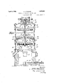
In the drawings, Fig. 1 comprises a vertical sectional view, partly broken away, through a furnacev comprising one embodiment of the invention;
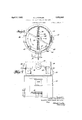
Fig. 2 shows in elevation part of afurnace as of Fig. l; J
Fig. 3 is a sectional view taken substantially alon the line 3-3 of Fig. 2; and
Fig. 4 sc ematically illustrates a plurality of drying or dewatering furnaces operatively associated with a calcining furnace.
The body of the furnace may comprise a cylindrical casting or a suitable sheet metal shell, as at 10, insulated if desired. This shell, of course, may be made of steel, brass,
various alloys, or special high temperature.
alloys, depending upon the service intended.
The cylindrical shell may be mounted upon a combustion chamber section of the furnace, as shown at 11. The'walls of the chamber may be made of any suitable heat-resisting material, and a suitable source of heat, such as 18 comprising upright cones.
an oil or gas burner as at 12, may be mounted within the combustion chamber. The burn- `er may be accompanied by a supplemental At the top of the combustion chamber, a4
suitable heat-resisting dome member, as at 16, may be provided, which also serves in part as the bottom of the furnace per se.
Within the shell 10 a plurality of vertically spaced or superposed conical hearths may be provided, as at 17 and 18. The hearths 17 may be detachably mounted and secured, as by key members 19, to a central rotatable shaft 20, which shaft in turn may be suspended from the top of the furnace, as by a thrust bearing 21. The hearths 17 are accordingly designed to rotate with the rotatable shaft. On the other hand, the hearths 18 may be made stationary and may be aiiixed to or supported from the cylindrical shell 10 by suitablebrackets, as at 22, which may be bolted or otherwise alxed to the shell l0. It will be observed that each of the hearths is substantially conical in shape, the hearths 17 comprising inverted cones and the hearths While but. three of the hearths are illustrated in Fig. 1, for simplicity, it will be understood that a complete furnace will comprise many more hearths, for example as many as from live to ten. It will also be understood that the hearths need not necessarily be conical in shape, so long as they comprise substantially surfaces of revolution for proper cooperation with rabble means hereinafter described.
The hearths 17 shown may be integrally formed with hub portions, as at 23, embracing the shaft 20, so that the lower portions of the conical area comprise, in effect, a receptacle capable of retaining considerable bodies of liquids or the like. The hearths 18, for the same purpose, may be integrally formed with peripheral upstanding flanges, as at 24. However, the hearths 18 are preferably made with central discharge openings, as at 25, through which the shaft 2() extends and through which material after treatment on the hearth is discharged to the hearth next below. The material is discharged from the hearths, such as 17 by causing the same to fall over theperipheral edges of the hearth to the next hearth below.
The rabbling means for advancing the material under treatment successively over each of the hearths may comprise both stationary and rotatable rabble arms, as at 26 and 27, respectively, the rabble arms 26 being removably mounted so as to extend through apertures, as at 28, in the shell 10. Removable .or fixed rabble teeth of any desired or conventional form, as at 29, may be provided along each of the rabble arms. Exteriorly of the shell 10 the rabble arms 26 may be provided with flanged portions, as at 30, designed to be bolted to the exterior of the shell. These portions may also be provided with exterior cavities or socket portions, as at 31, desi ned to be engaged by suitable tools or li ting means for removal of the rabble arms from the outside of the furnace. It will be observed that the openings 28, although designed to be normally covered by the flanges 30, are nevertheless of sufficient size to permit the rabble arms to be .y removed as assembled units, including the rabble teeth. Accordingly, whenever any diiiculty should arise with any particular rabble arm, the whole rabble arm assembly may be replaced by a spare without any considerable interference with the process going on. The rotatable rabble arms 27 at their inner ends may be formed with detachable hook portions, as at 32, engaging suit'- able apertures 33 and wedge members 34 as provided in spider members 35. The spider members 35 in turn are detachably secured to the rotatable shaft 20 by suitable keys in a manner similar to the attachment of the rotatable hearths 17. Suitable clean out or observation doors, as at 36 and 37, may also be provided opposite the various hearths. The rotatable rabble arms which are attached to the shaft may be removed through these observation doors without cooling the furnace.
At the top of the furnace a cover member, as at 38, may be provided, which also may serve as a supporting means for the thrust bearing 21 and, in addition, as a supporting means for a suitable speed reduction gear assembly, as at 39, driven from a suitable source of power and serving in turn to drive the rotatable shaft 20, through suitable bevel gears, as at 40.
The material to be treated in the furnace may be introduced through a feed inlet, as at 41, extending through the furnace top 38, and the gases of the furnace may be taken oil" through a gas outlet, as at 42, also extending vthrough the furnace cover or top. The matterial after treatment in the furnace may fall from the periphery of the lower hearth 17 onto the furnace bottom, as at 43, from which it may be scraped, as by a scraper 44, to a discharge spout 45. The scraper 44, as shown, may be detachably secured to the underside of the periphery of the rotatable hearth 17, as by a suitable form of mortise and tenon joint 46, as illustrated.
In order to guide the lower end of the shaft 20 as suspended from the single thrust bearing 21, suitable guide rollers, as at 47, may be provided to engage the peripheral edges of one of the lower rotatable hearths 17 The guide rollers 47 may be mounted in suitable removable flange plate members, as at 48, extending through openings in the furnace wall, as at 49. Four or more of the guide rollers', as at 47, may be placed around the periphery of the lower hearth, as indicated. The plate members 48, together with the guide rollers, which are rotatably mounted therein, may be readily applied and adjusted or removed from the exterior of the furnace for purposes of replacement or repair, etc.
The material treated in the furnace in passing down through the furnace is rabbled inwardly and outwardly, respectively, over the alternately arranged upright and inverted conical hearths, and in the meantime hot air and other heated gases from the combustion chamber 11 are permitted to pass up through an opening, as at 50, through the dome member 16, and thence upwardly through the furnace by passing around the peripheries of the rotatable hearths and through the central discharge openings 25 of the stationary hearths. By using a single thrust bearing, as at 21, for suspending the rotatable parts from the top of the furnace, the lower central portion of the furnace is left unobstructed, permitting the hot gases to be freely and symmetrically applied to the lower hearth. In addition, it will be observed that, by the use of a relatively large number of hearths, adequate capacity may be obtained with hearths of relatively small diameters. These conditions cooperate in precluding any tendency of the hot gases to confine their paths of travel to certain channels to the exclusion of other portions of the furnace, and consequently a uniform heating of the entire area of each hearth is insured- The furnace is well adapted for general industrial uses, such as dewatering and drying of very wet material, such as slimes, slurries and mixtures of waters and solids, and also for ordinary drying operations of material ,containing relatively smaller quantities of water. Also the furnace is adapted for drying of crystalline chemicals and for the evaporation of chemical liquors, in many in,
stances. Furthermore, l ert heated gases may be passed through the furnace, where other ascending hot gases might cause excessive combustion or undesired chemical changes.
It will be observed that each hearth may be dished or cupped to the desired extent, depending upon the character of the material to be treated, so that such material as first applied to the deep area of the hearth will be gradually worked by the rabble teeth toward the shallow or discharge areas, and will be discharged at a rate depending upon the speed of rotation and quantity of material admitted and the angle of the conical hea-rths, the heat applied, etc. The solid material will, of course, be more quickly advanced by the rabble teeth, so that the liquor will remain longer on each hearth and accordingly will be given ample time for the desired evaporation before being advanced to the succeeding hearths. V v
In drying or dewatering operations, considerable quantities of air are ordinarily required at a temperature of over 212J F. at the upper hearths, and the supplies of such air from the combustion chamber may be regulated as by burning extra fuel when necessary. l
All products of evaporation may be passed out of the furnace through the large gas outlet 42 at the furnace top and the dried residue through the discharge spout 45. The arrangement of the hearths and rabbles prevents the clogging of material on any hearths, since substantially all hearth areas are reached by rabbles, thus keeping all material constantly in motion and at the same time permitting the hearth areas to be fully ex posed to the heated air or gases.
` This furnace is adaptable for use in conjunction with calcining and roasting furnaces to d-eliver dried material to the top drying hearth of such furnaces. Furthermore, when thus used, the heated air as discharged from the air cooled rotatable shafts and rabble arms of such calcining furnaces may be readily in special cases, in-
`used as a drying medium in this dehydrating furnace merely by conducting such heated air or gases to the inlet 15. Furthermore, if desired, all of the outlet gases from the calcining or roasting furnaces may be passed through the drying furnace, as above described, for supplying the necessary heated air for carrying olil the moisture- When thus coordinated with the operation of the calcining or roasting furnaces, this Ydehydrating 'furnace is well adapted as a dust collector for the roasting furnace discharge gases. Inasmuch as the discharge gases gradually work their way up through this dehydrating furnace, the dust will be accumulated by the wet material on the hearths and thus avoiding the use of special dust accumulating means. In roasting operations 4carried on in connection with certain ores, for example, flotation sulfide concentrates containing as much as twenty per cent of water, the effective capacity of the roasting furnace can be substantially increased by first passing the wet material through a drying furnace, as above described, and furthermore the drying will be accomplished substantially without permitting caking or excessive lumping of the material, which would tend to preclude thorough treatment during the roasting operation, particularly if conducted rapidly.
It will be understood that the burner l2 indicated in the drawings is merely illustrative of one example. Other sources of heat may be utilize-d, such as coal or wood fires on standard grates. Furnace temperatures may behraised to any desirable practical degree, and for high temperatures shaft and rabble arm cooling arrangements known in the art may be resorted to, in which event the furnace may be utilized toroast various mate rials or even to liquefy certain materials.
The alternately arranged conical hearths 17 and-18 permit of a construction which avoids the use of small peripheral port areas common in other t es of furnaces, and consequently the possibility of clogging and caking is eliminated.
A group of the above described furnaces may be conveniently arranged around the circular wall of a large calcining furnace, so that outlet gases from the calcining furnaces may be distributed between the dehydrating furnaces, as desired. Such an arrangement is illustrated in Fig. 4, in which a calcining furnace is schematically indicated at 51, a drying furnace being indicated as at 52. Ma- 103 terial carriers are indicated as at 53 for conveying the dried or dewatered material from the furnaces 52 to the calcining furnace. Conduits as at 54 serve to convey the gases discharged from the calcining furnace to the 113 inlets 15 of the drying furnaces. If desired,- heated gases from the central shaft ofthe calcining furnace, which have been used for cooling the shaft and rabble arms, may be conveyed by conduits as at 55 tothe base of 113 the furnaces 52 as shown. Suitable damper regulating means may be provided in the conduits 54 and 55 as at 56 and 57 respectively. The calcining furnace may be of a type well known in the art, such for example as is 13 shown in numerous patents to Herreshoff, hence the details thereof need not be here described. l
The above described furnacekmay also be used in the preliminary treatment of fullers earth whichis to .be revivified, particularly where such fullers earth is too oily to be conveniently treated in an ordinary roasting furnace. For such uses, a steam jet ma be introduced in the above described furnace 13 `tab1e1`hearth mounted on said shaft comand the furnace used for-reducing the oil content of the fullers earth, which may later be more rapidly treated in a roasting furnace with more accurate control of the roasting temperatures.
While the invention hasbeen described in detail with respectfto particular preferred examples and methods of operation which give satisfactory results, it will be understood by those skilled in the art, after understanding the invention, that various changes and modifications may be made Without departing from the spirit and scope of the invention, and it is intended therefore in the appended claims to cover all such changes and modifications.`
What is claimed as new and desired to be secured by Letters Patent of the United States is:
1.y A drying furnace comprising a plurality of superposed alternately arranged rotary and stationary hearths, alternate hearths being respectively also substantially of upright and inverted cone shapes, the hearths'of upright conical shape having central discharge openings and rabbling means cooperating with each hearth.
2. In a furnace having a rotatable hearth, a relatively stationary rabbling arm assembly carrying rabble teeth and extending through the furnace Wall for cooperation with said hearth, and means for detachably aflixing said assembly to the exterior of the furnace Wall, the furnace Wall having an opening normally closed by the arm supporting portions such opening being of a size permitting the assembly to be removed to the exterior of the furnace as a unitary structure including its rabble teeth.
3. A multiple hearth furnace including a plurality of rotatable hearths mounted upon a rotatable shaft suspended from a thrust bearing at the top of the furnace.
4. A multiple hearth furnace including a plurality of rotatable hearths mounted upon a rotatable shaft suspended from a thrust bearing at the top of the furnace, and means engaging alower hearth substantially at its peripher for retaining the rotatable hearth and sha assembly against swinging Imovement.
5. A furnace comprising a rotatable hearth and shaft assembly suspended from a bearing at the upper part of the furnace, and a plurality of guiding means engaging a lower part of the assembly at points spaced substantially from the axis of rotation.
6. In a furnace having a rotatable hearth, a relatively stationary rabbling arm extending through the furnace Wall for cooperation with said hearth, and means for detachably aixing said arm to the exterior of the furnace Wall.
' 7. In a furnace having a rotatable shaft, a
prising a substantially annular concave casting embracing the shaft and detachably keyed thereto.
8. In a furnace having a rotatable shaft, a rotatable hearth mounted on said shaft comprising a substantially annular concave casting embracing the shaft and detachably keyed thereto, and rotatable rabbling means also detachably secured to said shaft for cooperation with other hearths.
9. In a furnace having a rotatable hearth, an enclosing Wall having an opening therethrough, a relatively stationary rabbling member extending through said opening in the Wall for cooperation with said hearth, and a cover for said opening, s'aid rabbling member being carried bv said cover and said cover beiig detachably affixed to the exterior of the Wa l.
10. A furnace having a rotatable shaft, a rotatable hearth mounted on said shaft cornprising an integral and conical casting embracing the shaft and detachably secured thereto at the center of he hearth.
1l. In a drying furnace having a vertically extending rotatable shaft, a plurality of rotatable hearths mounted on said shaft in spaced positions, each of said hearths comprfsing an integral conical member apertured at the center to embrace the shaft and slidable along the shaft into position thereon, and means for detachably securing each hearth in the desired position including a vertically extending sleeve encircling the shaft and integral With the hearth.
l2. In a drying furnace having a vertically extending rotatable shaft, a plurality of rotatable hearths mounted on said shaft in spaced positions, each of said hearths comprising a relatively thin integral metallic member apertured and provided with a vertically extending integral sleeve at its center for embracing the shaft, the hearths being slidable into position along the shaft, and means for detachably securing the sleeves of each of said hearths independently to the shaft. y
13. In a furnace having a rotatable shaft, a rotatable hearth mounted on said shaft comprising a substantially annular inte-gral casting embracing the shaft and detachably secured thereto, means for rabbling material under treatment on said hearth and for discharging the same from the periphery thereof to a surface beneath the hearth for supporting the material under treatment, and a member suspended froln the periphery of said hearth for advancing such material along and ofl' from said supporting area.
14. A furnace comprising an enclosing Wall and a plurality of superposed and relatively rotatable hearths therein, the lowermost of said hearths being rotatably carried by a vertical shaft, a substantially annular trough being provided at the bottom of the furnace beneath said lowermost hearth, a furnace outlet opening from said trough, and a scraper member detachably carried at the periphery of said lowermost hearth for advancing the material under treatment along said trough and to said outlet.
In testimony whereof I have signed my name to this specification.
EDITH MARY FOWLER, Ewecam' of the Las# Wz'ZZ and Testament of Edward J. Fowler, Deceased. a
Priority Applications (2)
| Application Number | Priority Date | Filing Date | Title |
|---|---|---|---|
| US260033A US1852646A (en) | 1928-03-08 | 1928-03-08 | Furnace for dewatering and the like |
| US583912A US1908645A (en) | 1928-03-08 | 1931-12-30 | Furnace construction |
Applications Claiming Priority (1)
| Application Number | Priority Date | Filing Date | Title |
|---|---|---|---|
| US260033A US1852646A (en) | 1928-03-08 | 1928-03-08 | Furnace for dewatering and the like |
Publications (1)
| Publication Number | Publication Date |
|---|---|
| US1852646A true US1852646A (en) | 1932-04-05 |
Family
ID=22987542
Family Applications (1)
| Application Number | Title | Priority Date | Filing Date |
|---|---|---|---|
| US260033A Expired - Lifetime US1852646A (en) | 1928-03-08 | 1928-03-08 | Furnace for dewatering and the like |
Country Status (1)
| Country | Link |
|---|---|
| US (1) | US1852646A (en) |
Cited By (3)
| Publication number | Priority date | Publication date | Assignee | Title |
|---|---|---|---|---|
| US2611975A (en) * | 1949-06-08 | 1952-09-30 | William D Taylor | Digester for manufacture of fertilizer |
| US3254425A (en) * | 1962-08-20 | 1966-06-07 | Carrier Mfg Co | Elevator drier |
| US20080015066A1 (en) * | 2003-04-02 | 2008-01-17 | Yamaha Hatsudoki Kabushiki Kaisha | Off-road vehicle with air intake system |
-
1928
- 1928-03-08 US US260033A patent/US1852646A/en not_active Expired - Lifetime
Cited By (3)
| Publication number | Priority date | Publication date | Assignee | Title |
|---|---|---|---|---|
| US2611975A (en) * | 1949-06-08 | 1952-09-30 | William D Taylor | Digester for manufacture of fertilizer |
| US3254425A (en) * | 1962-08-20 | 1966-06-07 | Carrier Mfg Co | Elevator drier |
| US20080015066A1 (en) * | 2003-04-02 | 2008-01-17 | Yamaha Hatsudoki Kabushiki Kaisha | Off-road vehicle with air intake system |
Similar Documents
| Publication | Publication Date | Title |
|---|---|---|
| US2030734A (en) | Furnace construction | |
| US3448012A (en) | Rotary concentric partition in a coke oven hearth | |
| US2091850A (en) | Apparatus for the performance of metallurgical or chemical reactions | |
| US3475286A (en) | Rotary heat treating oven | |
| US2323289A (en) | Coal drier | |
| US1852646A (en) | Furnace for dewatering and the like | |
| US2026441A (en) | Calciner | |
| US1293780A (en) | Apparatus for treating materials. | |
| US2031122A (en) | Furnace for roasting sulphurous ores | |
| US3208512A (en) | Heat exchanger for rotary kiln and the like | |
| US2117487A (en) | Incineration | |
| US1530154A (en) | Apparatus for the condensation of volatile metals such as zinc and the like | |
| US1825947A (en) | Roasting apparatus | |
| US2317941A (en) | Incineration of liquid sludge or the like | |
| US2110309A (en) | Incineration | |
| US2558963A (en) | Apparatus for roasting ores | |
| US2471882A (en) | Means for converting material | |
| US2128472A (en) | Incineration | |
| US1747740A (en) | Ore-reduction furnace | |
| US2559441A (en) | Rotary drum reactor | |
| US1516934A (en) | Apparatus for treatment of ores | |
| US1599072A (en) | Process of securing uniform revivification of activated carbon | |
| US2131665A (en) | Rotary muffle furnace | |
| US492551A (en) | Furnace for roasting | |
| US2277355A (en) | Chemical reaction furnace |