US1857719A - Fluid pressure engine - Google Patents
Fluid pressure engine Download PDFInfo
- Publication number
- US1857719A US1857719A US459218A US45921830A US1857719A US 1857719 A US1857719 A US 1857719A US 459218 A US459218 A US 459218A US 45921830 A US45921830 A US 45921830A US 1857719 A US1857719 A US 1857719A
- Authority
- US
- United States
- Prior art keywords
- lever
- levers
- rod
- valve
- centralizing
- Prior art date
- Legal status (The legal status is an assumption and is not a legal conclusion. Google has not performed a legal analysis and makes no representation as to the accuracy of the status listed.)
- Expired - Lifetime
Links
- 239000012530 fluid Substances 0.000 title description 12
- 230000003534 oscillatory effect Effects 0.000 description 4
- 208000036366 Sensation of pressure Diseases 0.000 description 1
- 230000006835 compression Effects 0.000 description 1
- 238000007906 compression Methods 0.000 description 1
- 239000007789 gas Substances 0.000 description 1
- 230000007935 neutral effect Effects 0.000 description 1
Images

Classifications
-
- F—MECHANICAL ENGINEERING; LIGHTING; HEATING; WEAPONS; BLASTING
- F01—MACHINES OR ENGINES IN GENERAL; ENGINE PLANTS IN GENERAL; STEAM ENGINES
- F01L—CYCLICALLY OPERATING VALVES FOR MACHINES OR ENGINES
- F01L29/00—Reversing-gear
- F01L29/04—Reversing-gear by links or guide rods
Definitions
- My invention relates to fluidpressure en 45 has an-inletport 79 coveredand uncovgines, operating with steam, compressed air, ered by an oscillatory valve 80, turned by a or other gases under pressure, and has parcrank 81.
- the port 7 9 is in communication ticular reference to improvements in the enwith a fluid pressure supply pipe 82, and a gine shown and described in Letters Patent pipes 73 and82 have'communication with a 65 No. 1,811,579, issued to me June 23, 1931. common.
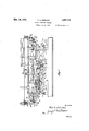
- FIG. 1 is a side elevation of an engine alternately openand closeinlet valve 74 and embodying my invention
- 1 exhaust valve 86 comprising vertically
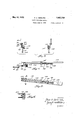
- Figure 2 is a diagrammatic view of valve swinging levers 88 and 89, pivotally supportactuating mechanism, ed at their lower ends, asshown at 90.
- FIG 3 is an edge elevation of the pivoted levers are arranged upon the same side of forked levers, for actuating the auxiliary the engine with the centralizing arm 58'.
- the inlet valves, leverv 88 is provided atits-upper end with a
- Figure 4 is a plan view of an operating rod, fork 91, having its ends attached to suitably
- Fig. 5 is a side elevation of the same, and, stiif retractile coil springs 92, whichextend 2:1
- Figure 6 is a transverse section taken on inwardly for suitable connection witha crank V 7 line 6--6 of Figure 5. 75, as shown in detail in my co-pending ap- In the drawings, wherein for the purpose plication.
- the lever 89 has a fork 95, which of illustration, is shown a preferre l'embodiis connected by identical means, including ment of my invention, the numerals 44' and springs 92 with the crank 87.
- the levers88 45 designate stationary cylinders. Mounted and 89 are connected by means of a'rod 96 to reciprocate within these cylinders are pispivoted thereto.
- the exhaust valve 77 is tons 46 and 47, respectively, rigidly attached opened and closed by means not a lever 97, to piston rods 48 and 49, having their inner connected with the crank 78 by the identical I ends connected with links 53, as described in yielding connectingmeans, described in conmy co-pending application.
- the inlet valve 80 is opened-and izing levers pivoted at their upper ends, as closed by means of a lever 98, connected with shown at 59 and pivotally connected with the the crank 81, by yielding means identicalwith links 53.
- the companion centralizing levers that described in connection with the lever 1 61 and 61, not shown in Figure 2, are con- 88, including the springs 92.
- the levers 97 nected with the links 53, asshown and 'deand 98 are disposed upon the opposite side scribed in my co-pending application, and of the c'ylinders'44 and 45, with respect to serve to drive the rotary driven element.
- the centralizing levers 58 and 58' are pondered at their lowerends, as shown at 99,
- a fluid pressure supply pipe 73 This inlet when they are shifted past dead center and port is covered and uncovered. by means of to hold the/same in the shifted posltions, as an oscillatory valve 74, turned'by a crank described in coo-pendingapplicat1on'as 75.
- the cylinder 44 has anexhaust port 76 shown in said amplication-No.1,811,579. Thls covered and 'uncoveredby an oscillatory means comprises generally a retract le coil valve 77, turned by a crank 78.
- the cylinder spring 103 connecting the cranks 75 and 78.
- cranks 81 and 87 are connected by a retractile coil spring 110. Stops 111 and 112 are disposed upon opposite sides of crank 87,'and stops 113 and 114 are disposed upon opposite sides of crank 81.
- the numeral 115 designates a shoe carried by the upper end ofthe vertical swinging lever 116, which is pivoted between its ends upon the rod 96, as shown at 117.
- this lever is connected with a retractile coil spring 118, the other end of which is attached to an arm 119, secured to the rod 96.
- a link 120 is pivotally connected with the upper end of the lever 116, as shown at 121, and the link is provided at its outer end with a slot 122, receiving a bolt 123, secured to the arm 124, which is attached to the rod 96. It is thus seen that the spring 118 and associated elements yieldingly oppose the outward swinging movement of the upper end of'the lever 116, within limits, but when the end wall of the slot 122 engages the bolt 123, this outward swinging movement of the lever 116 is positively stopped.
- a shoe 125 is carried by the upper end of the lever 126, which is pivoted to swing in a vertical plane between its ends, as shown at 127, upon the rod 96.
- a retractile coil spring 128 is secured to the lower end of the lever 126, and is attached to an arm 129, secured to the rod 96.
- a link 130 is pivoted to the upper end of the lever 126, as shown at 131, and has a slot 132 at its outer end, receiving a bolt 133, carried by an arm 134, secured to the r0d96. It is thus seen that the spring 128 and associated elements yieldingly oppose the outward swinging movement of the upper end of the arm 126, but
- a shoe 136 is mounted upon the rod 100 by the identical means as described in connec- Y .tion with the shoe 115, and a shoe 137 is The shoe 125 is set inwardly in advance of the shoe 137, and the shoe 136 has the same arrangement with respect to the shoe 15.
- Rods 140 and 140 are pivotally connected 'with'the lower ends of the centralizing levers 58 and 58, as shown at 141, at a point beneath the trip elements or rollers. These rods 140 and 140' extend in opposite directions toward the inlet pipes of the cylinders. Each rod 140 and 140 is provided with slug 142, rigidly attached thereto, and extending laterally therefrom. This lug isprovided with an aperture forslidably receiving a rod 143, extendinglongitudinally of the rod 140 or 140'.
- the rod 143 is provided near its outer end with a shoe 144, rigidly attached thereto, and this shoe has a lateral extension or guide 145, slidable in a longitudinal slot 146 formed in the rod 140.
- a second shoe 147 is rigidly attached to the rod 143 and has a lateral guide 148, slidable in the slot 146.
- a collar 148 is rigidly attached to the inner end of the rod 143.
- a compressible coil spring 149 surrounds the rod 143, between the shoe 147 and guide lug 142, and a 00111- pressible coil spring 150 surrounds the rod 143 between the guide lug 142 and sleeve 148.
- the numeral 151 designates a lever pivoted at its lower end,as shown at 152, with a stationary arm 153.
- This lever is provided at itsupper end, with a head 154,'arranged in the path of travel of the shoes 144 and 147, and this head carries a roller 155, arranged to operate between the arms 156 and 157, of a fork, carried by lever 158, pivoted at 159.
- the lever 158 has pivotal connection at 160,
- crank 163 is connected with an auxiliary oscillatory inlet valve 164.
- the crank 163 has connection with a retractile coil spring 165, attached to the end of a staand to retain the valve 164 in this position,
- centralizing lever 58 swings to the right, as explained, centralizing lever 58 swings to the right, shifting the rod 140 to the right, causing the inner shoe 147 to engage the head of the lever 151, swinging this lever to the right.
- the roller 155 now engages the arm 156, swinging lever 158, associated with cylinder 145 to the left.
- This 7 action of thelever 158 shifts link 161 to the left, and acts upon crank 163, and thereby opens valve 164, prior to the entrance of compressed air into the cylinder45, when roller 138 shifts shoe 137 and opens the valve 80, which occurs at the moment the piston 47 reaches the end of its out stroke in cylinder 45, and at the same movement opening exhaust valve 77 of cylinder 44.
- Pistons 46 and 47 having now reached the end of their stroke to the right, begin their stroke to the left, and centralizing levers 58 and 58 begin to swing to the left.
- Centralizing lever58 now shifts connecting rod 140 associated with the cylinder 45 to the right,'causing the outer shoe 144 carried by rod 140 to enga'ge'the upper end of the lever 151.
- the roller 145 carried by this lever will now engage the inner. arm 157 of the forked end of the lever 158, swinging lever 158 to the righttherebyclosing valve 164 of the cylinder 45, at the,
- a pairof opposed cylinders 1naininlet valves'for the cylinders, exhaust: valves for the cylinders, auxiliary inlet valves for controllingjthe passage of fluid pressure to the main inlet valves, pistons wlthin the cylinders, PlStOllI'OCl.
- rod means, pairs of swinging levers connected with the main in.- let valves and the outlet valves, wrods connecting the levers in said pairs, pairs of shoes carried by the rods,trip elementscarriedby the centralizing levers and disposed between the pairs of shoes for co-action therewith to shift.
- the main-inlet and outlet valves and operative connecting means between the centralizing levers. and the auxiliary inlet valve for closingthe auxiliary inlet valves prior to the closing of the main inlet valves.
- letvalves connected with the cylinders, aux iliary inlet Valves controlling the passage of fluid pressure tothe main inlet valves, pistons mounted within the cylinders, piston rod means connecting the pistons, a pair of centralizing levers connected with the piston rod means, pairs of swinging levers connected with the main inlet valves and exhaust -iso p ns...
- valves to actuate the same, a pair of connecting rods connecting the swinging levers "in such pairs, pairs of shoes carried by the rods, trip elements carried by the centralizing levers and disposed between the shoes to shift the main inlet and outlet valves, pivoted levers connected with the auxiliary inlet valves and having forked ends, actuating pivoted levers having parts to operate within said forked ends and swing the pivoted levers, and means Connected with the centralizing levers to engage and operate the actuating pivoted levers to shift the auxiliary inlet valves.
- a pair ofcylinders main inlet valves for the cylinders, outlet valves for the cylinders, auxiliary inlet valves for controlling the passage of fluid pressure to the main inlet valves, pistons within the cylinders, piston rod means connecting the pistons, centralizing levers connected with the piston rod means, means actuated by the centralizing levers for operating the main inlet valves and exhaust valves, pivoted levers having forked ends and connected with the auxiliary inlet valves, pivoted actuating levers having rollers to engage within the forked ends of the pivoted levers, rods pivotally connected with the centralizing levers, and a pair of spaced shoes carried by each rod and adapted to alternately engage the corresponding pivoted actuating lever' to shift the same.
Landscapes
- Engineering & Computer Science (AREA)
- Mechanical Engineering (AREA)
- General Engineering & Computer Science (AREA)
- Valve-Gear Or Valve Arrangements (AREA)
Description
May 10,1932. F. A. GERLING 1,357,719
FLUID PRESSURE ENGINE I Filed June 4, 1950 a Sheets-Sheet 1 gmnntov f7=o A. 65/81 ING,
ay ,1932. F. A. GERLING 1 FLUID PRES SURE ENGINE Filed June 4, 1930 3 Sheets-Sheet 2 INVENTOR.
a V Q W ATTORNEY.
May 10, 1932. AGERQNG 1,857,719
FLUID PRESSURE ENGINE Filed June 4," 1930 3 Sheets-Sheet 3 I N VEN TOR. Q [7M0 A. 65m uva,
ammal? A TTORNE Y.
Patented May 10, 1932 V i a 1 57 719 UNETED STATES FRED A. GERLING, or BOISE, IDAHO f FLUID PRESSURE ENGINE p Application filed June 4, 1930. Serial No. 459,218. i
My invention relates to fluidpressure en 45 has an-inletport 79 coveredand uncovgines, operating with steam, compressed air, ered by an oscillatory valve 80, turned by a or other gases under pressure, and has parcrank 81. The port 7 9 is in communication ticular reference to improvements in the enwith a fluid pressure supply pipe 82, and a gine shown and described in Letters Patent pipes 73 and82 have'communication with a 65 No. 1,811,579, issued to me June 23, 1931. common. source of fluid pressure.- The cylin- In the accompanying drawings, forming a der has an exhaust port 85, covered and part of this specification, and in which like uncovered by an oscillatoryvalve 86, turned numerals are employed to designate like parts by means of a crank 87. r throughout the same, 1 Valve shifting mechanism is provided to Figure 1 is a side elevation of an engine alternately openand closeinlet valve 74 and embodying my invention, 1 exhaust valve 86, comprising vertically Figure 2 is a diagrammatic view of valve swinging levers 88 and 89, pivotally supportactuating mechanism, ed at their lower ends, asshown at 90. These Figure 3 is an edge elevation of the pivoted levers are arranged upon the same side of forked levers, for actuating the auxiliary the engine with the centralizing arm 58'. The inlet valves, leverv 88 is provided atits-upper end with a Figure 4 is a plan view of an operating rod, fork 91, having its ends attached to suitably Fig. 5 is a side elevation of the same, and, stiif retractile coil springs 92, whichextend 2:1 Figure 6 is a transverse section taken on inwardly for suitable connection witha crank V 7 line 6--6 of Figure 5. 75, as shown in detail in my co-pending ap- In the drawings, wherein for the purpose plication. The lever 89 has a fork 95, which of illustration, is shown a preferre l'embodiis connected by identical means, including ment of my invention, the numerals 44' and springs 92 with the crank 87. The levers88 45 designate stationary cylinders. Mounted and 89 are connected by means of a'rod 96 to reciprocate within these cylinders are pispivoted thereto. The exhaust valve 77 is tons 46 and 47, respectively, rigidly attached opened and closed by means not a lever 97, to piston rods 48 and 49, having their inner connected with the crank 78 by the identical I ends connected with links 53, as described in yielding connectingmeans, described in conmy co-pending application. motion with the lever 88, including the The numerals 58 and 58' designate centralsprings 92.? The inlet valve 80 is opened-and izing levers pivoted at their upper ends, as closed by means of a lever 98, connected with shown at 59 and pivotally connected with the the crank 81, by yielding means identicalwith links 53. The companion centralizing levers that described in connection with the lever 1 61 and 61, not shown in Figure 2, are con- 88, including the springs 92. The levers 97 nected with the links 53, asshown and 'deand 98 are disposed upon the opposite side scribed in my co-pending application, and of the c'ylinders'44 and 45, with respect to serve to drive the rotary driven element. the levers 88 and 89, and are pivotally sup- M The centralizing levers 58 and 58' are emported at their lowerends, as shown at 99,
"' ployed in operating the valve shifting mechto swing in a vertical-plane longitudinally of 90 anism which constitutes the present 'inventhe cylinders. The levers 97 and 98 arecontion. p nected by a rod lOO. The same resilient means The cylinder 44, see particularly Figure 2, and stops are employed to swingthe cranks has an inlet port 72, in communication with which turn the inlet and v exhaust valves,
a fluid pressure supply pipe 73. This inlet when they are shifted past dead center and port is covered and uncovered. by means of to hold the/same in the shifted posltions, as an oscillatory valve 74, turned'by a crank described in coo-pendingapplicat1on'as 75. The cylinder 44 has anexhaust port 76 shown in said amplication-No.1,811,579. Thls covered and 'uncoveredby an oscillatory means comprises generally a retract le coil valve 77, turned by a crank 78. The cylinder spring 103 connecting the cranks 75 and 78.
Disposed upon opposite sides of the crank 75 are stops 104105, and disposed upon opposite sides of the crank 78 are stops 106 107. In a similar manner, cranks 81 and 87 are connected by a retractile coil spring 110. Stops 111 and 112 are disposed upon opposite sides of crank 87,'and stops 113 and 114 are disposed upon opposite sides of crank 81.
In view of the foregoing description, it will be seen that when the inlet valve 74 of the cylinder 44 is opened, exhaust valve 77 of this cylinder is closed while the exhaust valve 86 of the cylinder 45 is opened and the inlet valve 80 is closed, and vice versa.
The numeral 115 designates a shoe carried by the upper end ofthe vertical swinging lever 116, which is pivoted between its ends upon the rod 96, as shown at 117. The
' lower end of this lever is connected with a retractile coil spring 118, the other end of which is attached to an arm 119, secured to the rod 96. A link 120 is pivotally connected with the upper end of the lever 116, as shown at 121, and the link is provided at its outer end with a slot 122, receiving a bolt 123, secured to the arm 124, which is attached to the rod 96. It is thus seen that the spring 118 and associated elements yieldingly oppose the outward swinging movement of the upper end of'the lever 116, within limits, but when the end wall of the slot 122 engages the bolt 123, this outward swinging movement of the lever 116 is positively stopped. A shoe 125 is carried by the upper end of the lever 126, which is pivoted to swing in a vertical plane between its ends, as shown at 127, upon the rod 96. A retractile coil spring 128 is secured to the lower end of the lever 126, and is attached to an arm 129, secured to the rod 96. A link 130 is pivoted to the upper end of the lever 126, as shown at 131, and has a slot 132 at its outer end, receiving a bolt 133, carried by an arm 134, secured to the r0d96. It is thus seen that the spring 128 and associated elements yieldingly oppose the outward swinging movement of the upper end of the arm 126, but
'when the end wall of the slot 132 engages the bolt 133, such outward swinging movement of the lever 126 is positively stopped. The shoes 115 and 125 are arranged upon opposite sides and in the path of travel of a roller or trip element 135, which is mounted upon the centralizing lever 58, at a point near and above the connecting rod 96.
Whenthe centralizing lever 58 is in the vertlcal or neutral position, the roller 135 IS equi distantly' spaced from the shoes 115 and 125, and it is obvious that the roller upon the swinging movement of the centralizing lever 58 will alternately engage the shoes, thereby shifting the rod 96 in opposite directions.
. A shoe 136 is mounted upon the rod 100 by the identical means as described in connec- Y .tion with the shoe 115, and a shoe 137 is The shoe 125 is set inwardly in advance of the shoe 137, and the shoe 136 has the same arrangement with respect to the shoe 15.
A collar 148 is rigidly attached to the inner end of the rod 143. A compressible coil spring 149 surrounds the rod 143, between the shoe 147 and guide lug 142, and a 00111- pressible coil spring 150 surrounds the rod 143 between the guide lug 142 and sleeve 148.
The numeral 151 designates a lever pivoted at its lower end,as shown at 152, with a stationary arm 153. This lever is provided at itsupper end, with a head 154,'arranged in the path of travel of the shoes 144 and 147, and this head carries a roller 155, arranged to operate between the arms 156 and 157, of a fork, carried by lever 158, pivoted at 159.
The lever 158 has pivotal connection at 160,
with a link 161, which is pivoted at 162 with a crank 163. This crank 163 is connected with an auxiliary oscillatory inlet valve 164. The crank 163 has connection with a retractile coil spring 165, attached to the end of a staand to retain the valve 164 in this position,
until again shift-ed therefrom.
The operation of the engine is as follows: With the parts in the relative positions, as shown in Figure 2, exhaust valve 77 of cylinder 44 is closed and inlet valve 80 of 4 cylinder 45, is closed, with inlet valve 74 of cylinder 44 open and exhaust valve 86 of cylinder 45 open. Pistons 46 and 47 are traveling tothe right and lever 58 is swinging to the right, shifting rod 140 to the right. l
V This movement of the rod 140 moves the shoe the reservoir or tank, and this action is properly timed by the adjustment of the shoe 144 so that the valve 164 is closed at the proper interval, to utilize the expansion of the compressed air in the cylinder 44, acting against the piston 46, the maximum expansion being obtainable throughout the full stroke of the piston. The further traveling of the centralizing lever 58 to the right causes roller 135 to engage and shift the shoe 125, shifting the rod 96 to the right, closing valve 74, and at the same time closing valve 86, of the cylinder 45, as the piston 47 nears the end of its stroke, for producing a compression of the air within the cylinder 45, whereby the compressed air is received at full pressure when the valve 80 of cylinder 45 is opened, valve 77 being then also opened. When the centralizing lever 58 swings to the right, as explained, centralizing lever 58 swings to the right, shifting the rod 140 to the right, causing the inner shoe 147 to engage the head of the lever 151, swinging this lever to the right. The roller 155 now engages the arm 156, swinging lever 158, associated with cylinder 145 to the left. This 7 action of thelever 158 shifts link 161 to the left, and acts upon crank 163, and thereby opens valve 164, prior to the entrance of compressed air into the cylinder45, when roller 138 shifts shoe 137 and opens the valve 80, which occurs at the moment the piston 47 reaches the end of its out stroke in cylinder 45, and at the same movement opening exhaust valve 77 of cylinder 44. Pistons 46 and 47 having now reached the end of their stroke to the right, begin their stroke to the left, and centralizing levers 58 and 58 begin to swing to the left. Centralizing lever58 now shifts connecting rod 140 associated with the cylinder 45 to the right,'causing the outer shoe 144 carried by rod 140 to enga'ge'the upper end of the lever 151. The roller 145 carried by this lever will now engage the inner. arm 157 of the forked end of the lever 158, swinging lever 158 to the righttherebyclosing valve 164 of the cylinder 45, at the,
moment when the piston 47 reaches the relative reverse position of that occupied by the piston in cylinder 44, when valve 164 was closed, thereby utilizing the expansion of com-- pressed air in the cylinder 45, to the maximum, throughout the entire remaining portion of the stroke of the piston 47. Roller head of the lever 151, swinging this lever to the left and causing roller. 155 to engage. the arm 156, thereby swinging lever 158 to'the right, and opening auxiliary; inlet valve 164 prior to the opening of the valve'74, when the piston 46 reaches the endaof its stroke to the left. Roller 135 is finally brought into bringing shoe 14 7 into engagement with the engagement withshoe 115 thereby shifting 7 ,rod 96 to the left, and opening valves 74 and 86. The cycle of operating being completed the pistons 46 and 47 begin theirstroke to the right. V r I It is to be understood that the form' of my invention, herewith shown and described,
is to betakenas a preferred example ofithe same, andthat various changes in the shape,
size and arrangement of parts, may be resorted towithout departing from the spirit of my invention, or the scope of the subj oined.
claims. c 7
Having thus described my invention, I claim.:-..
1. In an engine,a pairof opposed cylinders, 1naininlet valves'for the cylinders, exhaust: valves for the cylinders, auxiliary inlet valves for controllingjthe passage of fluid pressure to the main inlet valves, pistons wlthin the cylinders, PlStOllI'OCl. means connecting the'pistons, a 'pair of centralizing I levers arranged near the cylinders and connected with the piston. rod means, pairs of swinging levers connected with the main in.- let valves and the outlet valves, wrods connecting the levers in said pairs, pairs of shoes carried by the rods,trip elementscarriedby the centralizing levers and disposed between the pairs of shoes for co-action therewith to shift. the main-inlet and outlet valves; and operative connecting means between the centralizing levers. and the auxiliary inlet valve for closingthe auxiliary inlet valves prior to the closing of the main inlet valves.
2. In an engine, a 'pairofcylinders, main inlet valves connected with the cylinders, out
letvalves connected with the cylinders, aux iliary inlet Valves controlling the passage of fluid pressure tothe main inlet valves, pistons mounted within the cylinders, piston rod means connecting the pistons, a pair of centralizing levers connected with the piston rod means, pairs of swinging levers connected with the main inlet valves and exhaust -iso p ns...
valves to actuate the same, a pair of connecting rods connecting the swinging levers "in such pairs, pairs of shoes carried by the rods, trip elements carried by the centralizing levers and disposed between the shoes to shift the main inlet and outlet valves, pivoted levers connected with the auxiliary inlet valves and having forked ends, actuating pivoted levers having parts to operate within said forked ends and swing the pivoted levers, and means Connected with the centralizing levers to engage and operate the actuating pivoted levers to shift the auxiliary inlet valves.
3. In an engine, a pair ofcylinders, main inlet valves for the cylinders, outlet valves for the cylinders, auxiliary inlet valves for controlling the passage of fluid pressure to the main inlet valves, pistons within the cylinders, piston rod means connecting the pistons, centralizing levers connected with the piston rod means, means actuated by the centralizing levers for operating the main inlet valves and exhaust valves, pivoted levers having forked ends and connected with the auxiliary inlet valves, pivoted actuating levers having rollers to engage within the forked ends of the pivoted levers, rods pivotally connected with the centralizing levers, and a pair of spaced shoes carried by each rod and adapted to alternately engage the corresponding pivoted actuating lever' to shift the same.
4. In an engine, a pair of cylinders, main inlet valves for the cylinders, outlet valves for the cylinders, auxiliary inlet valves for controlling the passage of fluid pressure to the main inlet valves, pistons within the cylinder's, piston rod means connecting the pistons, centralizing levers connected with the piston rod means, means actuated by the centralizing levers for operating the main inlet valves and the exhaust valves, pivoted levers having forked ends and connected with the auxiliary inlet valves, pivoted actuating levers having rollers to engage within the forked ends of the pivoted levers, rods pivotally connected with the centralizing levers and extending near the pivoted actuating levers, an auxiliary rod carried by each of the first named rods and movable longitudinally with relation thereto, and yielding means to oppose relative longitudinal movement of the auxiliary rod, a pair of spaced shoes carried by each auxiliary rod and adapted to engage upon opposite sides of the corresponding actuating lever to shift said auxiliary valve.
In testimony whereof I aflix my signature.
FRED A. GERLING.
Priority Applications (1)
| Application Number | Priority Date | Filing Date | Title |
|---|---|---|---|
| US459218A US1857719A (en) | 1930-06-04 | 1930-06-04 | Fluid pressure engine |
Applications Claiming Priority (1)
| Application Number | Priority Date | Filing Date | Title |
|---|---|---|---|
| US459218A US1857719A (en) | 1930-06-04 | 1930-06-04 | Fluid pressure engine |
Publications (1)
| Publication Number | Publication Date |
|---|---|
| US1857719A true US1857719A (en) | 1932-05-10 |
Family
ID=23823878
Family Applications (1)
| Application Number | Title | Priority Date | Filing Date |
|---|---|---|---|
| US459218A Expired - Lifetime US1857719A (en) | 1930-06-04 | 1930-06-04 | Fluid pressure engine |
Country Status (1)
| Country | Link |
|---|---|
| US (1) | US1857719A (en) |
Cited By (4)
| Publication number | Priority date | Publication date | Assignee | Title |
|---|---|---|---|---|
| US2445720A (en) * | 1945-09-26 | 1948-07-20 | Wenzel Wenzel Macquire & Richa | Opposed cylinder two-cycle engine |
| US2670720A (en) * | 1949-01-08 | 1954-03-02 | Trico Products Corp | Fluid motor valve means |
| US3149538A (en) * | 1962-04-20 | 1964-09-22 | Brollo Giuseppe | Hydraulic servo-mechanism |
| US20040005230A1 (en) * | 2002-07-03 | 2004-01-08 | Vockroth Richard W. | Hydraulic air compressor having an automatic water valve reulation mechanism |
-
1930
- 1930-06-04 US US459218A patent/US1857719A/en not_active Expired - Lifetime
Cited By (5)
| Publication number | Priority date | Publication date | Assignee | Title |
|---|---|---|---|---|
| US2445720A (en) * | 1945-09-26 | 1948-07-20 | Wenzel Wenzel Macquire & Richa | Opposed cylinder two-cycle engine |
| US2670720A (en) * | 1949-01-08 | 1954-03-02 | Trico Products Corp | Fluid motor valve means |
| US3149538A (en) * | 1962-04-20 | 1964-09-22 | Brollo Giuseppe | Hydraulic servo-mechanism |
| US20040005230A1 (en) * | 2002-07-03 | 2004-01-08 | Vockroth Richard W. | Hydraulic air compressor having an automatic water valve reulation mechanism |
| US6733253B2 (en) * | 2002-07-03 | 2004-05-11 | Richard W Vockroth | Hydraulic air compressor having an automatic water valve regulation mechanism |
Similar Documents
| Publication | Publication Date | Title |
|---|---|---|
| US1857719A (en) | Fluid pressure engine | |
| US1963444A (en) | Remote control apparatus for power driven boats and the like | |
| US3056353A (en) | Fluid actuated pump | |
| US1910019A (en) | Fluid-pressure motor | |
| US2264518A (en) | Valve operating means for duplex double-acting steam pumps | |
| US2439002A (en) | Power lever and engine using the same | |
| US1823639A (en) | Locomotive valve gear | |
| US2013609A (en) | Valve gear | |
| US1453561A (en) | Steam pump | |
| US961186A (en) | Steam-engine. | |
| US1720454A (en) | Locomotive valve gear | |
| US2713329A (en) | Steam engine | |
| US1009023A (en) | Reversing mechanism for explosive-engines. | |
| US359926A (en) | Steam-engine | |
| US1007278A (en) | Internal-combustion engine. | |
| US2488045A (en) | Pressure fluid servomotor for reversing gears | |
| US1680877A (en) | Fluid-pressure engine | |
| US1776963A (en) | Compressed-air engine | |
| US213615A (en) | Improvement in compound steam pumping-engines | |
| US1645574A (en) | Valve gear for power engines | |
| US2194970A (en) | Expansion engine | |
| US1582410A (en) | Twin compound marine steam engine | |
| US2383534A (en) | Locomotive drifting control mechanism | |
| US1760952A (en) | Motive-fluid engine | |
| US1820373A (en) | Throttle valve operating mechanism |