US1857717A - Hinge for window screens - Google Patents
Hinge for window screens Download PDFInfo
- Publication number
- US1857717A US1857717A US491302A US49130230A US1857717A US 1857717 A US1857717 A US 1857717A US 491302 A US491302 A US 491302A US 49130230 A US49130230 A US 49130230A US 1857717 A US1857717 A US 1857717A
- Authority
- US
- United States
- Prior art keywords
- screen
- hinge
- hinges
- frame
- window frame
- Prior art date
- Legal status (The legal status is an assumption and is not a legal conclusion. Google has not performed a legal analysis and makes no representation as to the accuracy of the status listed.)
- Expired - Lifetime
Links
- 210000005069 ears Anatomy 0.000 description 3
- RYGMFSIKBFXOCR-UHFFFAOYSA-N Copper Chemical compound [Cu] RYGMFSIKBFXOCR-UHFFFAOYSA-N 0.000 description 1
- 206010011878 Deafness Diseases 0.000 description 1
- 230000015572 biosynthetic process Effects 0.000 description 1
- 238000010276 construction Methods 0.000 description 1
- 239000002184 metal Substances 0.000 description 1
- 210000002105 tongue Anatomy 0.000 description 1
Images
Classifications
-
- E—FIXED CONSTRUCTIONS
- E05—LOCKS; KEYS; WINDOW OR DOOR FITTINGS; SAFES
- E05D—HINGES OR SUSPENSION DEVICES FOR DOORS, WINDOWS OR WINGS
- E05D7/00—Hinges or pivots of special construction
- E05D7/08—Hinges or pivots of special construction for use in suspensions comprising two spigots placed at opposite edges of the wing, especially at the top and the bottom, e.g. trunnions
- E05D7/081—Hinges or pivots of special construction for use in suspensions comprising two spigots placed at opposite edges of the wing, especially at the top and the bottom, e.g. trunnions the pivot axis of the wing being situated near one edge of the wing, especially at the top and bottom, e.g. trunnions
-
- E—FIXED CONSTRUCTIONS
- E05—LOCKS; KEYS; WINDOW OR DOOR FITTINGS; SAFES
- E05Y—INDEXING SCHEME ASSOCIATED WITH SUBCLASSES E05D AND E05F, RELATING TO CONSTRUCTION ELEMENTS, ELECTRIC CONTROL, POWER SUPPLY, POWER SIGNAL OR TRANSMISSION, USER INTERFACES, MOUNTING OR COUPLING, DETAILS, ACCESSORIES, AUXILIARY OPERATIONS NOT OTHERWISE PROVIDED FOR, APPLICATION THEREOF
- E05Y2900/00—Application of doors, windows, wings or fittings thereof
- E05Y2900/10—Application of doors, windows, wings or fittings thereof for buildings or parts thereof
- E05Y2900/13—Type of wing
- E05Y2900/148—Windows
Definitions
- the invention has for a further object to provide a hinge of the character stated which shall be adapted to be securedto a side of a Window frame by a single element functioning as its pivot and which shall be adapted to be secured to a stile of a screen without the aid of nails, screws or the like.
- the invention has for a further object to provide a hinge of the character stated which shall be adapted to permit a screen to be readily engaged therewith afterit has been secured to a window frame and which shall be adapted to permit the screen to be readily disengaged therefrom without disconnecting it from the window frame.
- the invention has fora further object to provide a hinge of the character stated which shall be neat and highly attractive and which shall be simple and capable of being manufactured and sold at a comparatively low cost.
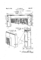
- Figure 1 is a view in front elevation illustrating the manner in which a screen is adapted to be hung in a window frame by hinges constructed in accordance with my invention.
- Figure 2 is a sectional view taken on a vertical plane indicated by the line 2-2 of Figure 1.
- Figure 3 is a sectional view taken on the horizontal plane indicated by the line 3+3 of Figure 1.
- Figure 4 is a view similar to Figure 3 with the screen occupying an outwardly extended 7 their frontand rear walls 9; contacting with position with respect to the Window frame.
- Figure 5 is-1a plan View. of the blankfrom which'the hinge is formedyand
- Figure 6 is a perspectiveview ofIa -fragmentary upper end portion of thescreeni
- 1 designates the upper portion of atwindowrf'rame, Qthe upper portion of a screenequal in width and length to the frame, and 3 thehinges by which thescreen is hung in the frame.
- the hingesB arelocated between thesides 4 of the frame 1 and the 'stiles'5 of;the screen 2, and are pivoted at their upper ends, asat 6, to the sides 4.
- the hinges 3 extend down wardly] from J their pivots 6 which :may consist ofnails', screws or the like.
- Thehinges 3 are ofchannel formation, and are open at, their upper andclosed at theirlowier ends.
- Ears 7 extending upwardly from the outer or side walls8fof thejhin'gesB, areprovided for the reception of the ,pivots6.
- Thehinges 3 receive the outer edge portions. of the stiles 5, theirjside walls 8 contacting ,with the; outer edges of, the stiles,
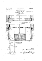
- Each of the hinges 3 isiadapted to be struck up from a single blank of sheet metal of suijti V able gage,the blankjbeing shown in Figure 5 and designated 14.
- the latter is bent along the dotted lines 15 and 16 to provide the hinge walls 8, 9*and10;
- the walls 9 are provided with extensions or tongues 17 which" are folded against the lower side of the wall K screen 2 maybe positione 10 so as to hold such wall against downward deflection by the weight of the screen 2.
- the blank 14 is provided at one end with an apertured extension which forms the ear 7.
- the hinges ,3 are pivotally secured to the sides 4 of the window frame 1 throughthe medium of the elements 6, the screen 2 is then provided with the notches 11, and thereafter the screen is engaged with the hinges.
- the hinges 3 are moved into engagement with the screen 2,- and thereafter the screen is swung into the window frame 1.
- the hinges'3 occupy but little space between the window frame 1 and screen 2, and the upper edge portions of the stiles 5 of the screen maybe cut away to facilitate the application of the screen to the hinges; While the hinges 3 are engaged with the screen 2 in a manner to prevent the screen I from becoming accidentally detached therefrom while within the frame 1 and while in angular position with respect to the frame, the hinges may be readily disengaged from the screen when it is desired to remove the latter, and this may be done by first swinging the screen outwardly from the window frame 1, and then deflecting the hinges into the signature.
- a hinge for connecting a movable frame to a fixed frame comprising a channel member adapted to receive a stile of the movable frame and adapted to have the upper end of its side wall pivoted to the fixed frame, a lug extending upwardly and inwardly from the lowerend of said wall and adapted't'o be embedded in said stile to secure said member to and hold it against lateral displacementf'rom the stile, and'extensions carried by the lower ends of the front and rear walls of said memher and underlying and contacting with said lug and adapted to be embedded in said stile.
Landscapes
- Engineering & Computer Science (AREA)
- Mechanical Engineering (AREA)
- Hinges (AREA)
Description
R. FOCARACCI HINGE FOR WINDOW SCREENS May 10, 1932 Filed Oct. 25, 1950 2. Sheets-Sheet Baa/"deaf MayIO, 1932. R. FocARAccl HINGE FOR WINDOW SCREENS 2 sheeis-sheet 2 Filed Oct. 25, 1930 gwue'ntoz R I [Zea/"a 0071 0} I I I v I l 1 v Patented May 10, 19327 RALPH rocARAcor, or'ivrIAMi", FLORIDA HINGE FOR WINDOW Application filed October 25, 19 30. SerialNo. 491,302. I i
' plied, and has for one of its objects to provide a hinge of this character which shall be adapted to permit a screen of this type to be hung with its top rail close to the head and its stiles close to the sides of a window frame.
The invention has for a further object to provide a hinge of the character stated which shall be adapted to be securedto a side of a Window frame by a single element functioning as its pivot and which shall be adapted to be secured to a stile of a screen without the aid of nails, screws or the like. i
The invention has for a further object to provide a hinge of the character stated which shall be adapted to permit a screen to be readily engaged therewith afterit has been secured to a window frame and which shall be adapted to permit the screen to be readily disengaged therefrom without disconnecting it from the window frame.
The invention has fora further object to provide a hinge of the character stated which shall be neat and highly attractive and which shall be simple and capable of being manufactured and sold at a comparatively low cost.
With the foregoing and other objects in view, the invention consists in the construction, combination and arrangement of parts hereinafter fullydescribed and claimed, and illustrated in the accompanying drawings, wherein:
Figure 1 is a view in front elevation illustrating the manner in which a screen is adapted to be hung in a window frame by hinges constructed in accordance with my invention.
Figure 2 is a sectional view taken on a vertical plane indicated by the line 2-2 of Figure 1.
Figure 3 is a sectional view taken on the horizontal plane indicated by the line 3+3 of Figure 1.
Figure 4 is a view similar to Figure 3 with the screen occupying an outwardly extended 7 their frontand rear walls 9; contacting with position with respect to the Window frame. Figure 5is-1a plan View. of the blankfrom which'the hinge is formedyand Figure 6 is a perspectiveview ofIa -fragmentary upper end portion of thescreeni Referring in detail to the drawings, 1 designates the upper portion of atwindowrf'rame, Qthe upper portion of a screenequal in width and length to the frame, and 3 thehinges by which thescreen is hung in the frame.
The hingesB arelocated between thesides 4 of the frame 1 and the 'stiles'5 of;the screen 2, and are pivoted at their upper ends, asat 6, to the sides 4. The hinges 3 extend down wardly] from J their pivots 6 which :may consist ofnails', screws or the like. Thehinges 3 are ofchannel formation, and are open at, their upper andclosed at theirlowier ends. Ears 7 extending upwardly from the outer or side walls8fof thejhin'gesB, areprovided for the reception of the ,pivots6. Thehinges 3 receive the outer edge portions. of the stiles 5, theirjside walls 8 contacting ,with the; outer edges of, the stiles,
the frontand rear faces of the stiles, and their end walls 10 constitutes lugs fittingin notches 11 formed in the stiles The walls lQeXtend upwardly and inwardly from the 1 side walls .8, and the notches. 11 extend upwardly and inwardly from the outer edges ofthe stiles 15 so that the engagement between;v the; walls 10 and notches 11 will be such as to hold the hinges "3 against outward movements. from the screen, 2, especially when thescreen has swung outwardlyfrom the frame 1. To insure thefree movement of-the hinges 3 on the pivots ,6 washers, 12; are. mounted upon the pivots between the ears 7 and frame-sides i and washers 13 are mountedupon thepivots between the heads. thereof and the ears. Each of the hinges 3 isiadapted to be struck up from a single blank of sheet metal of suijti V able gage,the blankjbeing shown in Figure 5 and designated 14. In forming the hinge from the blank 14, the latter is bent along the dotted lines 15 and 16 to provide the hinge walls 8, 9*and10; The walls 9 are provided with extensions or tongues 17 which" are folded against the lower side of the wall K screen 2 maybe positione 10 so as to hold such wall against downward deflection by the weight of the screen 2. The blank 14 is provided at one end with an apertured extension which forms the ear 7.
In practice, the hinges ,3 are pivotally secured to the sides 4 of the window frame 1 throughthe medium of the elements 6, the screen 2 is then provided with the notches 11, and thereafter the screen is engaged with the hinges. By swinging the hinges 3 outward= 1y from the window frame 1 and deflecting them laterally, as suggested by dotted lines in Figure 4:, the upper end dportion of the between the hinges. After this has been done, the hinges 3 are moved into engagement with the screen 2,- and thereafter the screen is swung into the window frame 1. The hinges'3 occupy but little space between the window frame 1 and screen 2, and the upper edge portions of the stiles 5 of the screen maybe cut away to facilitate the application of the screen to the hinges; While the hinges 3 are engaged with the screen 2 in a manner to prevent the screen I from becoming accidentally detached therefrom while within the frame 1 and while in angular position with respect to the frame, the hinges may be readily disengaged from the screen when it is desired to remove the latter, and this may be done by first swinging the screen outwardly from the window frame 1, and then deflecting the hinges into the signature.
dotted line position in which they are shown in Figure '4.
While I have the invention, together with the structure which I now consider the preferred embodiment thereof, it is to be understood that the structure shown is merely illustrative and that such changes may be made, when desired, as fall;within the scope of the inven-' tion as claimed. 7
What is claimed is Y A hinge for connecting a movable frame to a fixed frame,- comprising a channel member adapted to receive a stile of the movable frame and adapted to have the upper end of its side wall pivoted to the fixed frame, a lug extending upwardly and inwardly from the lowerend of said wall and adapted't'o be embedded in said stile to secure said member to and hold it against lateral displacementf'rom the stile, and'extensions carried by the lower ends of the front and rear walls of said memher and underlying and contacting with said lug and adapted to be embedded in said stile. Intestimony whereof I hereunto afiix my RALPH FOCARACOI.
described the principle of i
Priority Applications (1)
| Application Number | Priority Date | Filing Date | Title |
|---|---|---|---|
| US491302A US1857717A (en) | 1930-10-25 | 1930-10-25 | Hinge for window screens |
Applications Claiming Priority (1)
| Application Number | Priority Date | Filing Date | Title |
|---|---|---|---|
| US491302A US1857717A (en) | 1930-10-25 | 1930-10-25 | Hinge for window screens |
Publications (1)
| Publication Number | Publication Date |
|---|---|
| US1857717A true US1857717A (en) | 1932-05-10 |
Family
ID=23951624
Family Applications (1)
| Application Number | Title | Priority Date | Filing Date |
|---|---|---|---|
| US491302A Expired - Lifetime US1857717A (en) | 1930-10-25 | 1930-10-25 | Hinge for window screens |
Country Status (1)
| Country | Link |
|---|---|
| US (1) | US1857717A (en) |
Cited By (3)
| Publication number | Priority date | Publication date | Assignee | Title |
|---|---|---|---|---|
| US2764777A (en) * | 1955-04-20 | 1956-10-02 | Walter W Flieth | Concealed hinge structure |
| US2767442A (en) * | 1954-05-28 | 1956-10-23 | Stanley Building Specialties C | Hinge construction for pivotally mounted window sash |
| US3992005A (en) * | 1974-10-29 | 1976-11-16 | Richey John N | Billiard ball rack |
-
1930
- 1930-10-25 US US491302A patent/US1857717A/en not_active Expired - Lifetime
Cited By (3)
| Publication number | Priority date | Publication date | Assignee | Title |
|---|---|---|---|---|
| US2767442A (en) * | 1954-05-28 | 1956-10-23 | Stanley Building Specialties C | Hinge construction for pivotally mounted window sash |
| US2764777A (en) * | 1955-04-20 | 1956-10-02 | Walter W Flieth | Concealed hinge structure |
| US3992005A (en) * | 1974-10-29 | 1976-11-16 | Richey John N | Billiard ball rack |
Similar Documents
| Publication | Publication Date | Title |
|---|---|---|
| US960085A (en) | Hinge. | |
| US1750921A (en) | Adjustable door jamb | |
| US1857717A (en) | Hinge for window screens | |
| US1684027A (en) | Screen for windows of automobiles | |
| US1481142A (en) | Demountable hinge | |
| US1349438A (en) | Window-screen | |
| US1821136A (en) | Hinge | |
| US2005198A (en) | Automobile door | |
| US2153508A (en) | Hinged ventilator of the hopper type | |
| US2166815A (en) | Door hinge | |
| US1484024A (en) | Door | |
| US2510827A (en) | Hinge means | |
| US2312029A (en) | Door hinge | |
| US2587567A (en) | Louver window | |
| US1906237A (en) | Window screen for automobile doors | |
| US1632733A (en) | Metal receptacle | |
| US1775789A (en) | Doorcheck hinge | |
| US1368127A (en) | Window-hinge | |
| US1621047A (en) | Casement hinge | |
| US892993A (en) | Separable hinge for screens. | |
| US1617431A (en) | Oven door for stoves and the like | |
| US1732870A (en) | Ventilator | |
| US2256854A (en) | Transom-equipped door | |
| US734702A (en) | Awning-hinge. | |
| US2690214A (en) | Screen and door structure |