US1857585A - Ice auger - Google Patents
Ice auger Download PDFInfo
- Publication number
- US1857585A US1857585A US530983A US53098331A US1857585A US 1857585 A US1857585 A US 1857585A US 530983 A US530983 A US 530983A US 53098331 A US53098331 A US 53098331A US 1857585 A US1857585 A US 1857585A
- Authority
- US
- United States
- Prior art keywords
- ice
- reamer
- tool
- rib
- teeth
- Prior art date
- Legal status (The legal status is an assumption and is not a legal conclusion. Google has not performed a legal analysis and makes no representation as to the accuracy of the status listed.)
- Expired - Lifetime
Links
- 238000010276 construction Methods 0.000 description 2
- 208000032825 Ring chromosome 2 syndrome Diseases 0.000 description 1
- 239000002184 metal Substances 0.000 description 1
Images
Classifications
-
- A—HUMAN NECESSITIES
- A01—AGRICULTURE; FORESTRY; ANIMAL HUSBANDRY; HUNTING; TRAPPING; FISHING
- A01K—ANIMAL HUSBANDRY; AVICULTURE; APICULTURE; PISCICULTURE; FISHING; REARING OR BREEDING ANIMALS, NOT OTHERWISE PROVIDED FOR; NEW BREEDS OF ANIMALS
- A01K97/00—Accessories for angling
- A01K97/01—Accessories for angling for ice-fishing ; Ice drilling, hook-setting or signalling devices
Definitions
- Figure 3 is a transverse section taken approximately on the line 3 3 of Figure l;
- Figure 5 is a fraginental side elevation.
- the device forming the subject matter of this applica-tion preferably is made of metal throughout. It comprises a tubular body, including a cylinder l. About the lower end of the cylinder l, a reenforcing collar 2 is secured. Because the collar 2 is used,the cylinder l may be made lighter than would be the case otherwise, and the entire device, therefore, may be rotated without the eX- penditure of great power, a consideration which is of importa-nce in connection with a tool, which, ordinarily, is turned by hand.
- the collar 2 is provided at its lower end with -a circumerentia-lly-extended, upward ly-op'ening, outwardly-extended, trough- 'shaped reamer 4, which is locatedimmediately in advance of the tooth which has thernost pronounced outward slant, an observation which will be understood readily when Figure 2 of the Vdrawingsis noted.
- the reamer is located at the lower end of the spiral rib 51, as Figure 5 will show.
- the tool is further ⁇ characterized by the fact that the bottom 5 of the reamer4is disposed higher than the lower ends of the teeth 3, as shown in Figure l. Notingfthe point at which'the refer. ence numeral 36 is applied inv Figure 2, it will be seen that the reamer 4 extends laterallyan'd outwardly beyond the .circle in whichv operates the tooth which has the most pronounced outward slant.
- the cylinder lV is provided with spira ribs 7 and the ⁇ rib 50 onthe ring2 forming a 'continuation ofthe rib 7 Von the cylinder, ⁇ and the rib '51 on the ring forming a continuation of the rib 57 on the cylinder.4
- the reamer4 eX- tends outwardly to the outer edge of the rib 51e-57.
- the general construction shown at 3-4-36-6 is such that a smooth hole will be'bored in the ice, the vertical outer wall of.
- the reamer 4 finishing ⁇ the hole, beyond .the tooth 8 which has the most pronounced outward slant, a clear space being made underneath the ribs 7-50 and 57-51, the rib 57- 5l taking the loosened ice from the reamer 4,;V and carrying it upwardly,l when thebody of the tool is rotated, the reamer being at least f as wide as the area'cut by the teeth 3, and at least as wide as the ribs.
- the tool may be rotated in any desired l may be4 secured a reeniorcing collar v8, disposed within a cylindrical extension 9, of any desired length.
- Av headed securing element l0 passes removably through the upper end.
- a tool for making fishing holes in the ice comprising a tubular body provided at v,its lower end with depending teeth which slant outwardly at progressively increasing anglesthe body beingl supplied at its lower a circumferentially-extended, upwardly-opening, outwardly-e X 't e n d e d, trough-Shaped reamer, the body being provided with a spiral rib located above the teeth and leadingy from the reamer, the reamer being at least as wide as the. area. cut by the. teeth', ⁇ and at least as wide as the rib.
Landscapes
- Life Sciences & Earth Sciences (AREA)
- Environmental Sciences (AREA)
- Marine Sciences & Fisheries (AREA)
- Animal Husbandry (AREA)
- Biodiversity & Conservation Biology (AREA)
- Milling, Broaching, Filing, Reaming, And Others (AREA)
Description
May l0, 1932.
F. W. BROOKS. SR
ICE AUGER Filed April 17, 1951 2. Sheets-Sheet l amv/who@ May 10, 1932. F. w. BROOKS, SR
I C E AUGER Filed April 17,' 1931 L 2 Sheets-Sheet Patented May 10, 1932 FREDERICK W. BROOKS, SR.,
or VIRGINIA, MINNESOTA Ion Aurina Application ledvAprl 17,
The device forming the subject matter of this application is adapted to be employed for boring fishing holes in the ice. ln View of the fact that a fishing hole in the ice must be smooth, in order not to fray the iishing.
line, more is involved than simply making a hole of any kind in the ice, and the tool must be considered, not merely with respect to the hole that is bored, but, as well, `with respect to the fishing line, when the line is in use in the hole. Moreover, tools of the kind mentioned generally are operated by hand and not by power, because no power is available on the ice, and, therefore, the present tool is so constructed that it will bore a hole with a minimum expenditure of power.
It is within the province of the disclosure to improve generally and to enhance the utility of devices of that type to which the invention appertains. Y
With the above and other objects in view, which will appear as the description proceeds, the invention resides in the combination and arrangement of parts and in the details of construction hereinafter described and claimed, it being understood that changes in the precise embodiment of the invention herein disclosed, may be made within the scope of what is claimed, without departing from the spirit of the invention. Y
In the accompanying drawings:
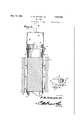
Figure l shows in side elevation, ah tool constructed in accordance with the invention;
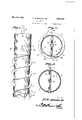
Figure 2 is an end elevation;
Figure 3 is a transverse section taken approximately on the line 3 3 of Figure l;
- Figure 4 is a longitudinal section;
Figure 5 is a fraginental side elevation. The device forming the subject matter of this applica-tion preferably is made of metal throughout. It comprises a tubular body, including a cylinder l. About the lower end of the cylinder l, a reenforcing collar 2 is secured. Because the collar 2 is used,the cylinder l may be made lighter than would be the case otherwise, and the entire device, therefore, may be rotated without the eX- penditure of great power, a consideration which is of importa-nce in connection with a tool, which, ordinarily, is turned by hand.
`way. About `the upper end of the cylinder 1931. seriai No'. 530,983.l
The collar 2 is providedat its lower end` with I I i depending pointed teeth 3,. which slant out-l wardly at progressively increasingfangles. The collar 2 has short spiralribs 50 andll,
which are oppositely disposed.v 55
The collar 2 is provided at its lower end with -a circumerentia-lly-extended, upward ly-op'ening, outwardly-extended, trough- 'shaped reamer 4, which is locatedimmediately in advance of the tooth which has thernost pronounced outward slant, an observation which will be understood readily when Figure 2 of the Vdrawingsis noted. The reamer is located at the lower end of the spiral rib 51, as Figure 5 will show. The tool is further `characterized by the fact that the bottom 5 of the reamer4is disposed higher than the lower ends of the teeth 3, as shown in Figure l. Notingfthe point at which'the refer. ence numeral 36 is applied invFigure 2, it will be seen that the reamer 4 extends laterallyan'd outwardly beyond the .circle in whichv operates the tooth which has the most pronounced outward slant. p :j
The cylinder lV is provided with spira ribs 7 and the `rib 50 onthe ring2 forming a 'continuation ofthe rib 7 Von the cylinder,` and the rib '51 on the ring forming a continuation of the rib 57 on the cylinder.4 As shown at 6 in Figure 2, the reamer4 eX- tends outwardly to the outer edge of the rib 51e-57. The general construction shown at 3-4-36-6 is such that a smooth hole will be'bored in the ice, the vertical outer wall of. the reamer 4 finishing `the hole, beyond .the tooth 8 which has the most pronounced outward slant, a clear space being made underneath the ribs 7-50 and 57-51, the rib 57- 5l taking the loosened ice from the reamer 4,;V and carrying it upwardly,l when thebody of the tool is rotated, the reamer being at least f as wide as the area'cut by the teeth 3, and at least as wide as the ribs.
The tool may be rotated in any desired l may be4 secured a reeniorcing collar v8, disposed within a cylindrical extension 9, of any desired length. Av headed securing element l0 passes removably through the upper end.,
of the cylinder 1, through the collar 8, and/'1130 through the lower end of the extension 9, and the securing element 10 may be held in place by its head, and by a cotter pin 11 mounted in the opposite end of the securing element. A bridge l2 is secured in the upper end of the extension 9, and carries a vertical shaft 14V which, being rotated either by hand, or by power, renders the` tool operative for the purposes intended'.
Having thus described the invention, what is claimed is:
1. A tool for making fishing holes in the ice, comprising a tubular body provided atits lower end with depending teeth which slant outwardly at progressively increasing angles, thebody being supplied at its lower end with a circumferentially-extended, upwardlyopening, outwardly-extended, trough-shaped end with reamer, located immediately in advance of the tooth which hasthe most pronounced outv ward slant.
2t. A tool for making lishing holes in the ice,
constructed as setr forth in claim l, and further characterized bythe fact that the botr' tomY of the reamer is disposed higher than the lower ends of the teeth, thev rea-mer eX- tendinglaterallyand outwardly beyond the circle in which said tooth moves.
3. A tool for making fishing holes in the ice, comprising a tubular body provided at v,its lower end with depending teeth which slant outwardly at progressively increasing anglesthe body beingl supplied at its lower a circumferentially-extended, upwardly-opening, outwardly-e X 't e n d e d, trough-Shaped reamer, the body being provided with a spiral rib located above the teeth and leadingy from the reamer, the reamer being at least as wide as the. area. cut by the. teeth',` and at least as wide as the rib.
In testimony that I claim the foregoing as `my own, I have hereto affixed my signature.
rFREDERICK WM. BROOKS, SR.
Priority Applications (1)
| Application Number | Priority Date | Filing Date | Title |
|---|---|---|---|
| US530983A US1857585A (en) | 1931-04-17 | 1931-04-17 | Ice auger |
Applications Claiming Priority (1)
| Application Number | Priority Date | Filing Date | Title |
|---|---|---|---|
| US530983A US1857585A (en) | 1931-04-17 | 1931-04-17 | Ice auger |
Publications (1)
| Publication Number | Publication Date |
|---|---|
| US1857585A true US1857585A (en) | 1932-05-10 |
Family
ID=24115783
Family Applications (1)
| Application Number | Title | Priority Date | Filing Date |
|---|---|---|---|
| US530983A Expired - Lifetime US1857585A (en) | 1931-04-17 | 1931-04-17 | Ice auger |
Country Status (1)
| Country | Link |
|---|---|
| US (1) | US1857585A (en) |
Cited By (8)
| Publication number | Priority date | Publication date | Assignee | Title |
|---|---|---|---|---|
| US2485123A (en) * | 1944-07-15 | 1949-10-18 | Pinchos E Medwed | Ice drill |
| US2666623A (en) * | 1950-12-21 | 1954-01-19 | Percy N Ross | Ice boring device |
| US2880968A (en) * | 1956-12-18 | 1959-04-07 | Louis R Titeca | Ice core drill |
| US3011598A (en) * | 1958-04-21 | 1961-12-05 | William H Galloway | Supporting post |
| USD363294S (en) | 1994-09-26 | 1995-10-17 | Ellis Albert D | Core drill bit |
| US6626250B1 (en) | 2002-04-12 | 2003-09-30 | Todd J. Ham | Ice auger shroud system |
| US20130272801A1 (en) * | 2011-08-25 | 2013-10-17 | Nippon Steel & Sumikin Engineering Co., Ltd. | Steel pipe pile and steel pipe pile implementation method |
| US12234726B1 (en) * | 2024-06-21 | 2025-02-25 | Brandon Price | Cylindrical ice auger bit for faster and easier hole drilling |
-
1931
- 1931-04-17 US US530983A patent/US1857585A/en not_active Expired - Lifetime
Cited By (9)
| Publication number | Priority date | Publication date | Assignee | Title |
|---|---|---|---|---|
| US2485123A (en) * | 1944-07-15 | 1949-10-18 | Pinchos E Medwed | Ice drill |
| US2666623A (en) * | 1950-12-21 | 1954-01-19 | Percy N Ross | Ice boring device |
| US2880968A (en) * | 1956-12-18 | 1959-04-07 | Louis R Titeca | Ice core drill |
| US3011598A (en) * | 1958-04-21 | 1961-12-05 | William H Galloway | Supporting post |
| USD363294S (en) | 1994-09-26 | 1995-10-17 | Ellis Albert D | Core drill bit |
| US6626250B1 (en) | 2002-04-12 | 2003-09-30 | Todd J. Ham | Ice auger shroud system |
| US20130272801A1 (en) * | 2011-08-25 | 2013-10-17 | Nippon Steel & Sumikin Engineering Co., Ltd. | Steel pipe pile and steel pipe pile implementation method |
| US9328475B2 (en) * | 2011-08-25 | 2016-05-03 | Nippon Steel & Sumikin Engineering Co., Ltd. | Steel pipe pile and steel pipe pile implementation method |
| US12234726B1 (en) * | 2024-06-21 | 2025-02-25 | Brandon Price | Cylindrical ice auger bit for faster and easier hole drilling |
Similar Documents
| Publication | Publication Date | Title |
|---|---|---|
| US1857585A (en) | Ice auger | |
| US1448243A (en) | Oil saver | |
| US1789399A (en) | Earth auger | |
| US1933595A (en) | Sand or sediment trap for pumping wells | |
| US1216628A (en) | Bit. | |
| US2508230A (en) | Ice auger | |
| US1665109A (en) | Trimmer | |
| US1114206A (en) | Earth-auger. | |
| US2090058A (en) | Drilling bit | |
| US1527413A (en) | Bit hook | |
| US1873240A (en) | Well drilling bit | |
| US1488648A (en) | Implement fob | |
| US1653883A (en) | Oil-well-tube scraper | |
| US1502463A (en) | Drill bit | |
| US1527108A (en) | Oil can | |
| US1736504A (en) | Well-drilling tool | |
| US1292842A (en) | Rotary drilling-tool. | |
| US1400132A (en) | Drill | |
| US1000817A (en) | Fishing-tool for oil or other wells. | |
| US1860253A (en) | Windmill and pump rod coupling | |
| US1477931A (en) | Drill bit | |
| US727322A (en) | Earth-auger. | |
| US1073005A (en) | Boring-bit. | |
| US1926635A (en) | Drill bit | |
| US616928A (en) | Signors op one-third to charles h |