US1857582A - Method of making forged compromise bars - Google Patents
Method of making forged compromise bars Download PDFInfo
- Publication number
- US1857582A US1857582A US188879A US18887927A US1857582A US 1857582 A US1857582 A US 1857582A US 188879 A US188879 A US 188879A US 18887927 A US18887927 A US 18887927A US 1857582 A US1857582 A US 1857582A
- Authority
- US
- United States
- Prior art keywords
- bar
- section
- flange
- compromise
- die
- Prior art date
- Legal status (The legal status is an assumption and is not a legal conclusion. Google has not performed a legal analysis and makes no representation as to the accuracy of the status listed.)
- Expired - Lifetime
Links
- 238000004519 manufacturing process Methods 0.000 title description 4
- 238000010008 shearing Methods 0.000 description 13
- 238000001816 cooling Methods 0.000 description 9
- 238000005242 forging Methods 0.000 description 7
- 238000004080 punching Methods 0.000 description 7
- 239000002184 metal Substances 0.000 description 5
- 238000000034 method Methods 0.000 description 4
- 238000005728 strengthening Methods 0.000 description 4
- 210000002445 nipple Anatomy 0.000 description 3
- 229910000831 Steel Inorganic materials 0.000 description 2
- 230000015572 biosynthetic process Effects 0.000 description 2
- 239000010959 steel Substances 0.000 description 2
- 229940037003 alum Drugs 0.000 description 1
- 235000019628 coolness Nutrition 0.000 description 1
- 230000003247 decreasing effect Effects 0.000 description 1
- 208000002925 dental caries Diseases 0.000 description 1
- 238000010438 heat treatment Methods 0.000 description 1
- 238000002844 melting Methods 0.000 description 1
- 230000008018 melting Effects 0.000 description 1
- 230000008520 organization Effects 0.000 description 1
- 238000005096 rolling process Methods 0.000 description 1
- 238000006467 substitution reaction Methods 0.000 description 1
- 230000003313 weakening effect Effects 0.000 description 1
Images

Classifications
-
- B—PERFORMING OPERATIONS; TRANSPORTING
- B21—MECHANICAL METAL-WORKING WITHOUT ESSENTIALLY REMOVING MATERIAL; PUNCHING METAL
- B21K—MAKING FORGED OR PRESSED METAL PRODUCTS, e.g. HORSE-SHOES, RIVETS, BOLTS OR WHEELS
- B21K9/00—Reconditioning railroad accessories, e.g. rails
Definitions
- both upper and lower fishing surfaces of the connector bar may be formed in one section, preferably the lower section.
- the fins caused thereby may be sheared off in a suitable shearin machine, and the bolt holes may be punche in a suitable punching machine.
- the bar may then a be allowed to cool slowl after which it may be heat treated to give t e bar proper tern or to withstand the working stresses to which it may be subjected in use.
- Some of the advantages in making a bar in this way are the formation of a bar hav- 7 ing sharpand abrupt offsets, which supports the rails substantially at the ends thereof, so as to minimize the up and down movement of the rail ends which causes the ends of the rails to be pounded by thewheels rolling thereon. According to the invention, this is accomplished without undul weakening the bar, either by decreasing t e cross section thereof or by setting up strains which affect the strength of the bar. Furthermore, the provision of a die in which both upper and ower fishing surfaces are formed by the same section thereof insures accuracy 1n the formation of the fishing surfaces.
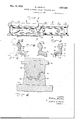
- ig. 1 is a side elevation showing f pronnse angle bar according to the invention applied to the inner or gage side of a pair 0 rails of different sections.
- Fig. 2 is a section on'the line 2-2 of Fi 1, taken through the larger end of the angle ar.
- Fig. 3 is a section similar to Fig. 2, taken on the line 3-3 of Fig. 1, through the angle bar at the smaller end.
- Fig. 4 is a section on the line 4-4 of'Fig. 1,. at substantially the middle of the angle bar showing the reenforcements. therein.
- Fig. 5 represents the appearance of the billet after it has been rough forged in the roughing die.
- Fig. 6 is a section through the forming die showing an an le bar formed into shape.
- Fig. 7 is a p an view of the lower section of the forming die.
- Fig. 8 is a section through a combined shearing and punching machine.
- Fi 9 is. a detail showing the male die mom ers used for punching the bolt holes.
- a single compromise angle bar made according to the in vention is shown connecting two rails of different section.
- the inner or gage side angle bar is shown for the purpose of illustrating the invention, it will be understood that the outer an le bar connecting the rails on their outer si es ma also be made 90. according to the teachings o the invention.
- Each rail may be of a standard sha e comprising a head, web and flange.
- T e rails may differ in one or more dimensions, such as height and width.
- the angle bar comprises a large end 10 adapted to fit the fishing section of the large rail 11, and a small and 12 adapted to fit the fishing section of the small rail 13.
- the large end as shown in Fig. is made up of a web 100 2 1,857,582 14, head and flange 16, the flange having Throughout the entire periphery of the die a depending rib 17 which is provided for recess 29, a clearance space 31 is left which strengthening purposes;
- the upper surface may be formed part in the upper section and 18 of the head is a fishing surface, and the part in the lower section, to allow s ace for lower surface 19 of the flange is also-a fishing the excess metal to be squeezed out.
- the small end 12 is'shaped similarly to the die mold to be completely filled.
- the bar is provided with 32 of a suitable hammer or press, and the *"ofisetportions adjacentthe point where the upper section being placed in the movable rails meet.
- The'angle bar is oifset upwardpart 33 of the hammer or press in proper ly from the large.-.-to"the' small end to take, alignment with thelower section. care of the di'salignment of the fishing sur- ⁇ Vhen the billet is formed to arough ap faces of the rails. In the angle bar shown in the roughing die a proper-temperature n the horizontal offset between the large and, should be used.
- a temperature several hunsmall ends is practically nil, but it will be dred degrees below the melting point isgen-i "appreciated that, if necessary, the bar may erally sufficient.
- the billet is to be be ivenan appreciable horizontal offs t in placed in the forming die, it may be reheatad ition to a vertical oifset.-.- ;.Th'e head 15 ed to a temperature sufficiently high to cause 25 and web 14 is provided with a strengthening the metal to flow easily when subjected to projection 22 at the point where the rails pressure in the die.
- the angle bar is further operated upon a projection 23 at this point, as shown clear-' before cooling by the apparatus shown in ly in Figs. 2, 3 and 4.
- the deviceshown in Figs. 30 The bar is provided with bolt holes 2 1 8 and 9 is a combined shearing machine and through the web thereof, along the center punching machine.
- the shearing machine lines at the large and small ends and is boltwill first be described. It comprises a' lower ed to the rails by bolts 25 as is well undersection 36 made up of a base 37 having a st od in the art.
- the modified billet 27 may then be i it receiving h b 1 p liaced in a forming die such as shown in Th hi hi comprises anup. 6 and I per section 45 and a lower section 46.
- the forming die shown comprises a 101 lower section 46 comprises the base 37 having 55 Section 28 made of Sultable matel'lll hfiwlng suitable recesses 48 and a plurality of shearv a recess 29 shaped to form the rail side of i i l 49 i l f h b lt 1 1 f the head and flange of the angle
- These nipples fit in the recesses in the base and to P fi necessary Q fi thereln-
- the and have openings 50 therein and clearance pp Sec/Q1011 3O the 13 made to fit the spaces 51 underneath.
- the nipples also have 30 lower section, and is shaped to form the other j ti ll 52 f proper h i ht, t 1 5 side of the web, head and flange f h ng tact and support the bar on the web thereof.
- r Shown cle ly 1n g- The 1 1
- the upper section 45 com rises the holder section cooperates to place the necessary oif- 42 h i g a plunger mem er suitably sesets in the angle bar, and also to form cured thereto.
- the plunger member is made the necessary strengthening projections. up of an attaching bar 53 having a plurality of plungers 54 suitably secured thereto, these plungers piercin the web and passing into the holes 50 in t e nipples, when the upper section moves downwardly.
- the bar is then allowed to cool slowly, and if desired, after cooling, the spike notches 26, are punched in the flange. After the bar cools sufficiently, it may be subjected to suitable heat treatment to strengthen the bar, andut it; in the best condition for with.- stan in use. i
- the-improved g the stresses which it must Withstand I which” comprises, forming a billet of steel to a rough shape, forging the rough shape in a forming die to a finished shape having a projecting fin, thereb forming t e fishing surfaces on the web an flange in one section of the forming die, removing the fin, unching bolt holes inthe web, cooling t e bar slowly, and then heat-treating said bar.
- the method of makin a compromise angle bar having a web, ange and offset which comprises, forging a suitable billet in a forming die to a finished shape having a projecting fin, removing the fin before cooling, punching bolt holes in the web before cooling, cooling the bar slowly, and then heat-treating said bar.
Landscapes
- Engineering & Computer Science (AREA)
- Mechanical Engineering (AREA)
- Forging (AREA)
Description
May 10, 1932.
METH6D OF MAKING FORGED COMPROMISE .BARS
Filed y 5, 1927 2 Sheets-Sheet l w. BENDER ,857,582
h I M.
- INVENTOR. Ma alum BY M 11 M" A TTORNEY I May 10, 1932. w. BENDER'V 7 1,857,582
' 7 METHOD OF MAKING FORGED COMPROMISE BARS Filed May 1927 2 Sheets-Sheet 2 I INVENTOR."
A TTORNEY latentedlviay n, was
fs rAT-Es PATENT caries wnmux BENDEB, or nowms oaovn, ILLINOIS, assranoa 'ro nma'ronux ooze-h 'EORATION, OB NEW YORK, N. Y., A-CORPOBATION OF NEW YORK HETHDD F WGFQEGED CQMPROMISE BARS i I Y Application filed May 5, 1927. Serial 170. 188,879.
both upper and lower fishing surfaces of the connector bar may be formed in one section, preferably the lower section. After the forgmg operation, the fins caused thereby may be sheared off in a suitable shearin machine, and the bolt holes may be punche in a suitable punching machine. The bar may then a be allowed to cool slowl after which it may be heat treated to give t e bar proper tern or to withstand the working stresses to which it may be subjected in use.
Some of the advantages in making a bar in this way are the formation of a bar hav- 7 ing sharpand abrupt offsets, which supports the rails substantially at the ends thereof, so as to minimize the up and down movement of the rail ends which causes the ends of the rails to be pounded by thewheels rolling thereon. According to the invention, this is accomplished without undul weakening the bar, either by decreasing t e cross section thereof or by setting up strains which affect the strength of the bar. Furthermore, the provision of a die in which both upper and ower fishing surfaces are formed by the same section thereof insures accuracy 1n the formation of the fishing surfaces.
Various other features and advantages of the invention will be apparent from the following particular description and from an ins ction of the accompanying drawings.
though the novel features which are believed to be characteristic of this invention will be pointed out with particularity in the claims ap nded hereto, the invention itself, as to its ohiects and advantages, the mode of its operation and the manner of its organization may be better understood by referring to the following description takenin connewtion with the accompanying drawings forma in a part thereof, in which ig. 1 is a side elevation showing f pronnse angle bar according to the invention applied to the inner or gage side of a pair 0 rails of different sections. Fig. 2 is a section on'the line 2-2 of Fi 1, taken through the larger end of the angle ar. Fig. 3 is a section similar to Fig. 2, taken on the line 3-3 of Fig. 1, through the angle bar at the smaller end. Fig. 4 is a section on the line 4-4 of'Fig. 1,. at substantially the middle of the angle bar showing the reenforcements. therein.
Fig. 5 represents the appearance of the billet after it has been rough forged in the roughing die.
Fig. 6 is a section through the forming die showing an an le bar formed into shape.
Fig. 7 is a p an view of the lower section of the forming die.
Fig. 8 is a section through a combined shearing and punching machine.
Fi 9 is. a detail showing the male die mom ers used for punching the bolt holes.
In the following description and in the claims parts will be identified by specific names for convenience, but theyare intended to be as generic in their application to similar parts as the art will permit.
Referring now to the drawings and more particularly to Figs.'1 to 4, a single compromise angle bar made according to the in vention is shown connecting two rails of different section. Although only the inner or gage side angle bar is shown for the purpose of illustrating the invention, it will be understood that the outer an le bar connecting the rails on their outer si es ma also be made 90. according to the teachings o the invention. Each rail may be of a standard sha e comprising a head, web and flange. T e rails may differ in one or more dimensions, such as height and width.
The angle bar comprises a large end 10 adapted to fit the fishing section of the large rail 11, and a small and 12 adapted to fit the fishing section of the small rail 13. The large end, as shown in Fig. is made up of a web 100 2 1,857,582 14, head and flange 16, the flange having Throughout the entire periphery of the die a depending rib 17 which is provided for recess 29, a clearance space 31 is left which strengthening purposes; The upper surface, may be formed part in the upper section and 18 of the head is a fishing surface, and the part in the lower section, to allow s ace for lower surface 19 of the flange is also-a fishing the excess metal to be squeezed out. lightly 70 surface, these surfaces fitting the head and more metal is placed in the billet than is nec flange of the rail, respectively. essary to make a finished bar to insure the The small end 12 is'shaped similarly to the die mold to be completely filled. The clearlarge end, and has an upper fishing surface ance space31 accommodates the excess metal 20 and a lower fishing surface 21 adapted to which is squeezed out during forging. "l5 fit the head and flange respectively of the It will be understood that the die sections small rail 13 as shown clearly. in Fig.3. are placed in suitable holders, the'lower sec- To take care of the difference in sections tion 28 being placed uponthe base or table between the rails, the bar is provided with 32 of a suitable hammer or press, and the *"ofisetportions adjacentthe point where the upper section being placed in the movable rails meet. The'angle bar is oifset upwardpart 33 of the hammer or press in proper ly from the large.-.-to"the' small end to take, alignment with thelower section. care of the di'salignment of the fishing sur- \Vhen the billet is formed to arough ap faces of the rails. In the angle bar shown in the roughing die a proper-temperature n the horizontal offset between the large and, should be used. A temperature several hunsmall ends is practically nil, but it will be dred degrees below the melting point isgen-i "appreciated that, if necessary, the bar may erally sufficient. hen the billet is to be be ivenan appreciable horizontal offs t in placed in the forming die, it may be reheatad ition to a vertical oifset.-.- ;.Th'e head 15 ed to a temperature sufficiently high to cause 25 and web 14 is provided with a strengthening the metal to flow easily when subjected to projection 22 at the point where the rails pressure in the die. meet, and the flange 16 is also provided with The angle bar is further operated upon a projection 23 at this point, as shown clear-' before cooling by the apparatus shown in ly in Figs. 2, 3 and 4. Figs. 8 and 9. The deviceshown in Figs. 30 The bar is provided with bolt holes 2 1 8 and 9 is a combined shearing machine and through the web thereof, along the center punching machine. The shearing machine lines at the large and small ends and is boltwill first be described. It comprises a' lower ed to the rails by bolts 25 as is well undersection 36 made up of a base 37 having a st od in the art. Spi e mat es 26 m y a s chamber 38 in which the finished bar may 35 be provided in the flange if desi d. drop. Positioned over the chamber is alower The shape of the angle bar is such that shearing member 39, havin an openingd l the rails'receive support therefrom at subf h ha o that its e gs supports the v stantially the extreme ends thereof. The bar by the fin 40 thereof, around the entire forging process makes this possible. The oifperiphery of. the bar; j r QF y be made q e Sharp d b p The upper section 41 of'the shearing rimwithout setting up undesirable strains in the hi i d up f a it bl h ld 42, d metal and h bill at the Ofi'set y b an upper shearing member 43 shaped to fit trelgthened If desired y means 0f the P the surface of the bar, and having shearing JeCtloIlS Shown. edges which co-operate with the shearing 45 T0 make an a g bar of the character edges of the lower shearing member. It will above described a billet of the proper kind b d t d th t th upper d lower 9 Stet/1 y be first rough forged a htions are properly aligned, and that the uping die to a shape 27 somewhat as shown in per shearing member is moved downwardly gthls l bemg 5ub$ mnt1any toward and into the lower shearing member 50 tangular, and having a thick side and a thin t h -Off th fi th b th d i 11;
side. The modified billet 27 may then be i it receiving h b 1 p liaced in a forming die such as shown in Th hi hi comprises anup. 6 and I per section 45 and a lower section 46. The The forming die shown comprises a 101 lower section 46 comprises the base 37 having 55 Section 28 made of Sultable matel'lll hfiwlng suitable recesses 48 and a plurality of shearv a recess 29 shaped to form the rail side of i i l 49 i l f h b lt 1 1 f the head and flange of the angle These nipples fit in the recesses in the base and to P fi necessary Q fi thereln- The and have openings 50 therein and clearance pp Sec/Q1011 3O the 13 made to fit the spaces 51 underneath. The nipples also have 30 lower section, and is shaped to form the other j ti ll 52 f proper h i ht, t 1 5 side of the web, head and flange f h ng tact and support the bar on the web thereof. r, Shown cle ly 1n g- The 1 1 The upper section 45 com rises the holder section cooperates to place the necessary oif- 42 h i g a plunger mem er suitably sesets in the angle bar, and also to form cured thereto. The plunger member is made the necessary strengthening projections. up of an attaching bar 53 having a plurality of plungers 54 suitably secured thereto, these plungers piercin the web and passing into the holes 50 in t e nipples, when the upper section moves downwardly.
The bar is then allowed to cool slowly, and if desired, after cooling, the spike notches 26, are punched in the flange. After the bar cools sufficiently, it may be subjected to suitable heat treatment to strengthen the bar, andut it; in the best condition for with.- stan in use. i
Thus, it will be seen that the-improved g the stresses which it must Withstand I which" comprises, forming a billet of steel to a rough shape, forging the rough shape in a forming die to a finished shape having a projecting fin, thereb forming t e fishing surfaces on the web an flange in one section of the forming die, removing the fin, unching bolt holes inthe web, cooling t e bar slowly, and then heat-treating said bar.v
-' testimony whereof, I have hereunto set my. l andnncl seal.
. process produces an angle bar which has 0tf set portions which are quite shear and abrupt, giving support to the rails su Stan-" tially at the ends thereof. The drop forging j 1 operation places these ofi'sets in the bar andthereof in such manner to prevent relative vertical movement of the rails.
While certain novel features of the inven tion are shown and described and are pointed out in the annexed claims, it will be understood that various omissions, substitutions and changes in the process and apparatus above disclosed may be made by those skilled in the art without departing from the spirit of the invention.
What is claimed is: 1. The method of making a angle bar having a head, web and flange, offset and strengthening projections, which comprises, forging a billet of steel to a rough compromise v shape in a roughing die, forging the rough shape in a forming die to a finished shape having a projecting fin, thereby forming the fishing surfaces on the head and flange in one section of the forming die, shearing off the fin before cooling in a shearing die, punching bolt holes in the web before cool ing, cooling the bar slowly, punching spike notches in the flange, and then heat-treating said bar. r
2. The method of makin a compromise angle bar having a web, ange and offset which comprises, forging a suitable billet in a forming die to a finished shape having a projecting fin, removing the fin before cooling, punching bolt holes in the web before cooling, cooling the bar slowly, and then heat-treating said bar.
3. The method of making a compromise angle bar having a web, flange and offset WILLIAM n'nunnn.
Priority Applications (1)
| Application Number | Priority Date | Filing Date | Title |
|---|---|---|---|
| US188879A US1857582A (en) | 1927-05-05 | 1927-05-05 | Method of making forged compromise bars |
Applications Claiming Priority (1)
| Application Number | Priority Date | Filing Date | Title |
|---|---|---|---|
| US188879A US1857582A (en) | 1927-05-05 | 1927-05-05 | Method of making forged compromise bars |
Publications (1)
| Publication Number | Publication Date |
|---|---|
| US1857582A true US1857582A (en) | 1932-05-10 |
Family
ID=22694938
Family Applications (1)
| Application Number | Title | Priority Date | Filing Date |
|---|---|---|---|
| US188879A Expired - Lifetime US1857582A (en) | 1927-05-05 | 1927-05-05 | Method of making forged compromise bars |
Country Status (1)
| Country | Link |
|---|---|
| US (1) | US1857582A (en) |
Cited By (1)
| Publication number | Priority date | Publication date | Assignee | Title |
|---|---|---|---|---|
| US2617179A (en) * | 1950-05-10 | 1952-11-11 | Mcdonnell Aircraft Corp | Method of manufacturing tapered beams |
-
1927
- 1927-05-05 US US188879A patent/US1857582A/en not_active Expired - Lifetime
Cited By (1)
| Publication number | Priority date | Publication date | Assignee | Title |
|---|---|---|---|---|
| US2617179A (en) * | 1950-05-10 | 1952-11-11 | Mcdonnell Aircraft Corp | Method of manufacturing tapered beams |
Similar Documents
| Publication | Publication Date | Title |
|---|---|---|
| DE3885946T2 (en) | Composite structures and methods of making the same. | |
| EP3088092B1 (en) | Hot forming and press hardening tool and method for operating the hot forming and press hardening tool | |
| DE2630040A1 (en) | METHOD AND DEVICE FOR MANUFACTURING A FLAT BED RIM | |
| US1977299A (en) | Manufacture of grating | |
| US1857582A (en) | Method of making forged compromise bars | |
| EP2528711B1 (en) | Punching tool | |
| CN109465375B (en) | Die forging method for high-speed railway turnout iron seat | |
| EP0345279B1 (en) | Process for manufacturing metal parts | |
| US1439352A (en) | Method of and apparatus for forming metal | |
| US1659776A (en) | Method of treating worn rail joints | |
| US2822708A (en) | Method of making a forging die | |
| US1700775A (en) | Method of making rail anchors | |
| SU897377A1 (en) | Die for volumetric forming of finned articles | |
| US693186A (en) | Mandrel for shaping hollow or tubular wrought-metal articles. | |
| US2790227A (en) | Process of making crank shafts | |
| EP4321271B1 (en) | Method of manufacturing a motor vehicle component by hot forming with integrated trimming | |
| US2016089A (en) | Method of making plowshares | |
| DE60309950T2 (en) | Method for producing a forged connecting rod and tool for carrying out the method | |
| US1596687A (en) | Method and apparatus for making rail-joint members | |
| US176667A (en) | Improvement in dies for the manufacture of shovel-blocks | |
| US1236062A (en) | Method of making tie-plates. | |
| US2046297A (en) | Roadway joint strip | |
| DE300459C (en) | ||
| US171141A (en) | Improvement in the manufacture of grubbing-hoes | |
| US1818880A (en) | Method of forming a compromise rail joint bar |