US1857579A - Automobile transmission hoist - Google Patents
Automobile transmission hoist Download PDFInfo
- Publication number
- US1857579A US1857579A US328666A US32866628A US1857579A US 1857579 A US1857579 A US 1857579A US 328666 A US328666 A US 328666A US 32866628 A US32866628 A US 32866628A US 1857579 A US1857579 A US 1857579A
- Authority
- US
- United States
- Prior art keywords
- bearing
- automobile transmission
- drum
- shaft
- transmission hoist
- Prior art date
- Legal status (The legal status is an assumption and is not a legal conclusion. Google has not performed a legal analysis and makes no representation as to the accuracy of the status listed.)
- Expired - Lifetime
Links
- 230000005540 biological transmission Effects 0.000 title description 7
- 238000010276 construction Methods 0.000 description 4
- 150000003278 haem Chemical class 0.000 description 1
- 238000004519 manufacturing process Methods 0.000 description 1
- 230000000630 rising effect Effects 0.000 description 1
- 210000003813 thumb Anatomy 0.000 description 1
Images
Classifications
-
- B—PERFORMING OPERATIONS; TRANSPORTING
- B60—VEHICLES IN GENERAL
- B60S—SERVICING, CLEANING, REPAIRING, SUPPORTING, LIFTING, OR MANOEUVRING OF VEHICLES, NOT OTHERWISE PROVIDED FOR
- B60S11/00—Vehicle modifications for receiving separate lifting, supporting, or manoeuvring devices
Definitions
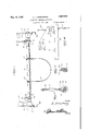
- Figure l is an elevation of the device embodying the features of this invention showing the same supported on the side rails of an automobile frame, said rails being shown in section,
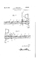
- Figure 2 is a longitudinal section through one end thereof, a
- Figure 3 is a longitudinal section through the other end thereof
- Figure 4 is an end elevation thereof
- Figure 5 is a sectional viewtaken substantially on the line 5-5 of Figure 1, I
- Figure 6 is a sectional view taken substantially on the line 66 of Figure 1,
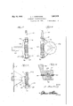
- FIG. 7 is a detail view showing another operating mechanism
- Figure 8 is a view taken to that shown in Figure 7,
- Figure 9 is a view showing the embodiment in place in the stand.
- Figure 10 is an enlarged detail section therethrough.
- numerals 5 denote the stands each of which is provided :with a; pair of bearing receiving members 6.
- one stand. is a bearing .7 with a pawl supporting extension rising from theinner end thereof.
- the hollow shafts 10 are provided with slots 14 and the drum is provided with screws 15' extending into the slots 14: 0 that the drum and shaft turn as a unitubllt the shafts may be moved in and out of the drum to-increase or decreas the-length flf heme ei f 7 menu.
- Fastening elements 16 are mounted on the drum so that the ends of acable .17 may be engaged therwith.
- a ratchet wheel 22" is mounted on the other shaft 10 by means of pin 23 and apawl-2i is pivotedbya pin 25 to the support extension 8 of the bearing 7 to engage with the ratchet wheel 22.
- the shaft 10 and drum maybe turned towind the V cable on the drum for hoisting or supporting the transmission and the cable is prevented from unwinding because of the pawl-24sene gaging the ratchet pawl Qfmay beswung out of, engagement Wi h the ra che Wheel 22 so, a to p rmi the lowering" of the transmission or thedisengagementof the cable 1'1 therefrom.
- pawls 20 and 24 are spring pressed; as iss wn o advantag irespectively atel Figure 5, an 52 in F gur -7 wheel 22.
- the numeral denotes a bearing for disposal in one of the members 6, the inner end of the bearing having a horizontal bracket 36 which includes diverging arms terminating in end portions 37 for receiving bearing blocks 38 and 39.
- the block 38 is pivotally mounted by screws 40 while the block 39 is held in place by thumb screws 41.
- a shaft 42 is ournaled in the blocks 38 and 39 and has a worm 43 fixed thereon for swinging movement with the shaft into and out of mesh with a worm gear 44 on one of the shafts 10. Any suitable means may be engaged with the shaft 42 to turn the worm 43 and the worm gear 44 thereby rotating the respective shafts 10 so as to Wind the cable on the drum as will be quite apparent.
- the screws 41 may be unloosened so that the block 39 is free to be swung out of its respective end 37 causing the block 38 to pivot thereby unmeshing the worm from the worm gear so that the shaft 10 and parts connected thereto may be rotated quickly through hand manipulation of the worm gear 44.
- a hoisting mechanism comprising in combination a pair of opposed stands, each of which comprises a body portion having bearing receiving members projecting laterally from one side thereof adjacent the upper and lower edges thereof, said bearing receiving members being arranged diagonally with re- 'spect to one another, a bearing for reception in a selected one of said bearing receiving members, and a rotatable element supported between said stands and having its ends jour nalled in said bearings, said rotatable member being longitudinally extensible, whereby said stands may be placed the desired distance apart,
Landscapes
- Engineering & Computer Science (AREA)
- Mechanical Engineering (AREA)
- Fittings On The Vehicle Exterior For Carrying Loads, And Devices For Holding Or Mounting Articles (AREA)
Description
May 10, 1932. J. ARMSTRONG AUTOMOBILE TRANSMISSION HOIST 5 Sheets-Sheet l Filed- Dec. 27, 1928 Inventor Z, zfi wrwffoly' Bygg 9w an .1 s N A .3 w .h 4 fiumj g F 4 m m 3 w Q\ W\ w Q m m\ W Attorney 3 Sheets-Sheet 2 Filed Dec.
Attorney May 10, 1932. .1 ARMSTRONG 1,857,579
AUTOMOBILE TRANSMISSION HOIST Filed Dec. 27, 1928 5 Sheets-Sheet 3 Invenior A itorny Patented May 10, 1932 UNITED STATES PATENT .oFF ce LEONARD J. ARMSTRONG, or MARINEBSVHARBOB, NEW Yo tx AUTOMOBILE TRANSMISSION HoIsT Application filed December 27, 1928. Serial No.'328 ,666.
1 mobile transmission hoist of this nature which is exceedingly simple in its construction, adjustable, easy to manipulate, strong and durable, inexpensive to manufacture, thoroughly eflicient and reliable in use and 15 operation, and otherwise well adapted to the purpose for which it is designed.
IVith the above and numerous other objects in view as will appear as the description proceeds, the invention resides in certain 20 novel features of construction, and in the combination and arrangement of parts as will be hereinafter more fully described and claimed.
In the drawings: a
Figure l is an elevation of the device embodying the features of this invention showing the same supported on the side rails of an automobile frame, said rails being shown in section,
Figure 2 is a longitudinal section through one end thereof, a
Figure 3 is a longitudinal section through the other end thereof,
Figure 4 is an end elevation thereof,
Figure 5 is a sectional viewtaken substantially on the line 5-5 of Figure 1, I
Figure 6 is a sectional view taken substantially on the line 66 of Figure 1,
Figure 7 is a detail view showing another operating mechanism,
Figure 8 is a view taken to that shown in Figure 7,
Figure 9 is a view showing the embodiment in place in the stand, and
Figure 10 is an enlarged detail section therethrough.
Referring to the drawings in detail and first the embodiment of the invention dis at right angles 50 closed in Figures 1 to 2 inclusive it will be seen that numerals 5 denote the stands each of which is provided :with a; pair of bearing receiving members 6. In one of these bearing eceiving members o one stand. is a bearing .7 with a pawl supporting extension rising from theinner end thereof.
In one of the bearlng receiving members 6 ofthe. other stand 5 there isva bearing 9. Tubuliar shafts lOqare rotatablein the bearings"? and 9 and have collars or outwardly directed annular flanges 11 at their outer endswhile their inner ends are telescoped into. a hollow drum 12.
The hollow shafts 10 are provided with slots 14 and the drum is provided with screws 15' extending into the slots 14: 0 that the drum and shaft turn as a unitubllt the shafts may be moved in and out of the drum to-increase or decreas the-length flf heme ei f 7 menu. Fastening elements 16 are mounted on the drum so that the ends of acable .17 may be engaged therwith.
' Onone shaft lOthere is fixed by means of a pin 18 a ratchet wheel 19 about'which is rotatable a lever 19" having a-pawl 20'en, gageable with theratohet wheell9 and operable by a rod 21 extended through the lever 19'. a f
A ratchet wheel 22" is mounted on the other shaft 10 by means of pin 23 and apawl-2i is pivotedbya pin 25 to the support extension 8 of the bearing 7 to engage with the ratchet wheel 22. r i a v a I From the above detailed description it will be seen that the mechanism or apparatus may be extended so that the'stan'dsb rest on the siderails 3Q ofa'n automobile frame with the able 17 x en g nder the transmis ion thereof. Then by rocking the lever 19? the shaft 10 and drum maybe turned towind the V cable on the drum for hoisting or supporting the transmission and the cable is prevented from unwinding because of the pawl-24sene gaging the ratchet pawl Qfmay beswung out of, engagement Wi h the ra che Wheel 22 so, a to p rmi the lowering" of the transmission or thedisengagementof the cable 1'1 therefrom. The
The block 38 is pivotally mounted by screws 40 while the block 39 is held in place by thumb screws 41. A shaft 42 is ournaled in the blocks 38 and 39 and has a worm 43 fixed thereon for swinging movement with the shaft into and out of mesh with a worm gear 44 on one of the shafts 10. Any suitable means may be engaged with the shaft 42 to turn the worm 43 and the worm gear 44 thereby rotating the respective shafts 10 so as to Wind the cable on the drum as will be quite apparent.
To provide for quick adjustment the screws 41 may be unloosened so that the block 39 is free to be swung out of its respective end 37 causing the block 38 to pivot thereby unmeshing the worm from the worm gear so that the shaft 10 and parts connected thereto may be rotated quickly through hand manipulation of the worm gear 44.
' It is thought that the construction, operation, utility and advantages of this invention in this art without a more iii will now be quite apparent to those skilled detailed description thereof.
The present embodiment of the invention has been disclosed in detail merely for the purposes of exemplification since in actual practice it attains the features of advantage enumerated as desirable in the statement of the invention and the above description.
It will be apparent that changes in the details of construction, and in the combination and arrangement of parts may be resorted to without departing from the spirit or scope of the invention as hereinafter claimed or sacrificing any of its advantages.
Having thus described my invention, what I claim as new is:
A hoisting mechanism comprising in combination a pair of opposed stands, each of which comprises a body portion having bearing receiving members projecting laterally from one side thereof adjacent the upper and lower edges thereof, said bearing receiving members being arranged diagonally with re- 'spect to one another, a bearing for reception in a selected one of said bearing receiving members, and a rotatable element supported between said stands and having its ends jour nalled in said bearings, said rotatable member being longitudinally extensible, whereby said stands may be placed the desired distance apart,
In testimony whereof I affix my signature.
LEONARD J .ARMSTRONGL I
Priority Applications (1)
| Application Number | Priority Date | Filing Date | Title |
|---|---|---|---|
| US328666A US1857579A (en) | 1928-12-27 | 1928-12-27 | Automobile transmission hoist |
Applications Claiming Priority (1)
| Application Number | Priority Date | Filing Date | Title |
|---|---|---|---|
| US328666A US1857579A (en) | 1928-12-27 | 1928-12-27 | Automobile transmission hoist |
Publications (1)
| Publication Number | Publication Date |
|---|---|
| US1857579A true US1857579A (en) | 1932-05-10 |
Family
ID=23281906
Family Applications (1)
| Application Number | Title | Priority Date | Filing Date |
|---|---|---|---|
| US328666A Expired - Lifetime US1857579A (en) | 1928-12-27 | 1928-12-27 | Automobile transmission hoist |
Country Status (1)
| Country | Link |
|---|---|
| US (1) | US1857579A (en) |
Cited By (3)
| Publication number | Priority date | Publication date | Assignee | Title |
|---|---|---|---|---|
| US3447785A (en) * | 1967-08-18 | 1969-06-03 | Jack H Brown | Winch for raising and lowering motor vehicle engines |
| US4703917A (en) * | 1986-06-12 | 1987-11-03 | Carfel Inc. | Manual winch with drum release and handle storage |
| US7182318B1 (en) * | 2004-03-24 | 2007-02-27 | Brandon Crabtree | Method and apparatus for removing and installing a differential of a vehicle |
-
1928
- 1928-12-27 US US328666A patent/US1857579A/en not_active Expired - Lifetime
Cited By (3)
| Publication number | Priority date | Publication date | Assignee | Title |
|---|---|---|---|---|
| US3447785A (en) * | 1967-08-18 | 1969-06-03 | Jack H Brown | Winch for raising and lowering motor vehicle engines |
| US4703917A (en) * | 1986-06-12 | 1987-11-03 | Carfel Inc. | Manual winch with drum release and handle storage |
| US7182318B1 (en) * | 2004-03-24 | 2007-02-27 | Brandon Crabtree | Method and apparatus for removing and installing a differential of a vehicle |
Similar Documents
| Publication | Publication Date | Title |
|---|---|---|
| US1857579A (en) | Automobile transmission hoist | |
| US2267355A (en) | Barrel handling apparatus | |
| CN208134333U (en) | A kind of tower transport vehicle | |
| US1453323A (en) | Mixing apparatus | |
| US2874935A (en) | Automobile bumper jack | |
| US1533443A (en) | Pipe-bending machine | |
| US2555457A (en) | Chalk line reel and stake | |
| US1290267A (en) | Transportable adjustable automobile-rack. | |
| US3089229A (en) | Combination reversible puller | |
| US667788A (en) | Reel-holder. | |
| US783672A (en) | Ice-hoist. | |
| US1786360A (en) | Line-pole-setting device | |
| US1290926A (en) | Roof-jack. | |
| US1142738A (en) | Windlass. | |
| US1369194A (en) | Automobile lift or hoist | |
| US1003072A (en) | Hand-derrick. | |
| US2261509A (en) | Automatic log wagon power take-off loader and unloader | |
| US82774A (en) | Andrew j | |
| US1225030A (en) | Tiltable turn-table. | |
| US600973A (en) | Hand-hoist | |
| US1471992A (en) | Motor stand | |
| US1697290A (en) | Ice saw and crusher | |
| US1852436A (en) | Stabilizing means for concrete mixers | |
| US1956094A (en) | Derrick | |
| US940729A (en) | Clothes-reel. |