US1857560A - Tie member for tanks - Google Patents
Tie member for tanks Download PDFInfo
- Publication number
- US1857560A US1857560A US355029A US35502929A US1857560A US 1857560 A US1857560 A US 1857560A US 355029 A US355029 A US 355029A US 35502929 A US35502929 A US 35502929A US 1857560 A US1857560 A US 1857560A
- Authority
- US
- United States
- Prior art keywords
- tie
- rods
- tank
- tanks
- edge
- Prior art date
- Legal status (The legal status is an assumption and is not a legal conclusion. Google has not performed a legal analysis and makes no representation as to the accuracy of the status listed.)
- Expired - Lifetime
Links
- 240000002329 Inga feuillei Species 0.000 description 1
- 102100038750 Myc-associated zinc finger protein Human genes 0.000 description 1
- 101710146400 Myc-associated zinc finger protein Proteins 0.000 description 1
- ATJFFYVFTNAWJD-UHFFFAOYSA-N Tin Chemical compound [Sn] ATJFFYVFTNAWJD-UHFFFAOYSA-N 0.000 description 1
- 238000004873 anchoring Methods 0.000 description 1
- 238000005554 pickling Methods 0.000 description 1
- 230000003014 reinforcing effect Effects 0.000 description 1
Images
Classifications
-
- C—CHEMISTRY; METALLURGY
- C23—COATING METALLIC MATERIAL; COATING MATERIAL WITH METALLIC MATERIAL; CHEMICAL SURFACE TREATMENT; DIFFUSION TREATMENT OF METALLIC MATERIAL; COATING BY VACUUM EVAPORATION, BY SPUTTERING, BY ION IMPLANTATION OR BY CHEMICAL VAPOUR DEPOSITION, IN GENERAL; INHIBITING CORROSION OF METALLIC MATERIAL OR INCRUSTATION IN GENERAL
- C23G—CLEANING OR DE-GREASING OF METALLIC MATERIAL BY CHEMICAL METHODS OTHER THAN ELECTROLYSIS
- C23G3/00—Apparatus for cleaning or pickling metallic material
Definitions
- the invention comprises the novel structure and combination of parts hereinafter described and more particularly pointed out and defined in the appended claims.
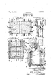
- Y 3o Figure 1 is a top plan view of a pickling tank involving this invention.
- Figure 2 is an end elevational view of such tank.
- Figure 3 is an enlarged sectional View taken upon the line III-III of Figure 1.
- Figure 4L is an enlarged sectional view taken upon the line IV'-IV of Figure 1.
- Figure 5 is an enlarged elevational view of a lower clamping member.
- Figure 6 is an enlarged top planvview of an upper clamping member.
- thepickling tank orvat is shown as a rectangular wooden ybox-like structure consisting of sides 1, ends 2 and a bottom 3.
- the bottom 3 consists of suitable boards or planks arranged side by side.
- the sides 1 consist of suitable boards or planks la arranged edge upon edge to form a wall.
- the planks forming the sides of the vat are In the accompanying drawings which i1-V ROBERT L. LEWIS, oF RATAVIA, ILLINoIs, AssIefNoRv To oLInLLRIvern, comrnlvaer; f-f RATAvIA, ILLINOIS, A CORPORATION onILLINoIs Y I TIE MEMBER non Tankst 1929. sensing. 355,029'.
- each lower clamping member consists of a' ⁇ vertical cylin'fV Y.
- drical bearing portion 9a toreceivothe rod? ahorizontal'rest9b'upon whichgthe lower" Y' V endl of the strut 8 'rests and afoot'9c extending under the side wall of the tankg
- Each lower clamp 9 is also provided witha'horizontal cylindrical bearing9el to receive la'-transverse ro 1o.
- the floor is preferably l grooved #transversely adjacent its ends as indicated at 11 (Fig. ⁇ 3)* to receive the loweredges of theend walls.
- the floor extends ⁇ beyondthe endV walls and supports the lower ends "of en d struts 8 which inclineoutwardlyand,
- End ytie rods'll ⁇ connect theend clamps fwith-theiioor.”
- the end tie rods preferably extend through the floor and through reinforcing members orbeams Q-12 extending transversely below the licor.V
- suitable end tie rods 13 connect the said sides.'-Reinforcing uprights'14 are placed in'- the Vplane of the tie rods13 and the ends of the tie Arods 13 extend therethrough.
- tank of the characterzdescribeda 'wal-l consisting; of longitudinalboards a1"-Y ranged' edge-upon; edge, clampin vmembers upon-the'topand bottom ofv thewa l,tie rods outside. of saidwall and(v connecting said clampngmembers and ⁇ struts between said clamping members.
- IngaV tankl of the .character describedf having a bottom, a wall consistingof boards: Y arrangededgeupon edge, clamping members 351 engaginggover theltop of said wall,4 adjustiable-tiero'ds fastenedto said clamping mem ⁇ bers and anchored withirespeot to thebottomz and struts adjns-tably'jengaging; the outer par-ts of said. clam-ping; members and xedly 49Af'secured; with respect to the bottom for the pur1 )ose ,set ⁇ forth.
- said clamps having; seatsv spaced: outwardlyv from saidztiefrods and. an; inclined stnutibe-,4 v tweenesaidf seats, 50- 4f., Inzaitank of the character-described hav:-
- Inatestimony rwhereoifflV have hereuntov sub-V scribedamy ,namei at Batavia, Illinois', county'V of; Kane: s e 3 Y f f ROBERCEL.
Landscapes
- Chemical & Material Sciences (AREA)
- Chemical Kinetics & Catalysis (AREA)
- General Chemical & Material Sciences (AREA)
- Engineering & Computer Science (AREA)
- Materials Engineering (AREA)
- Mechanical Engineering (AREA)
- Metallurgy (AREA)
- Organic Chemistry (AREA)
- Load-Engaging Elements For Cranes (AREA)
Description
May 10, 1932. l R, LEwls Y 1,857,560
TIE MEMBER FOR TANKS Filed April 15, 1929 Patented May 1o, 1932 UNITED s'rxras Application filed April 15,
or buckle, creating leaking cracks in the walls.
It is an object of this invention to overcome this bulging or buckling tendency in .the walls of the tank in the provision of clamping means that exercises a straight downward pull. Itis a further object of this invention to eliminate the usual rod holes in the center of planks by placing the tie rods outside of the tank.
The invention comprises the novel structure and combination of parts hereinafter described and more particularly pointed out and defined in the appended claims.
lustrate a preferred form of this invention and in which similar reference numerals refer to similar features in the dierent views.
On the drawings: Y 3o Figure 1 is a top plan view of a pickling tank involving this invention.
Figure 2 is an end elevational view of such tank.
Figure 3 is an enlarged sectional View taken upon the line III-III of Figure 1.
Figure 4L is an enlarged sectional view taken upon the line IV'-IV of Figure 1.
Figure 5 is an enlarged elevational view of a lower clamping member.
Figure 6 is an enlarged top planvview of an upper clamping member.
As shown on theV drawings:
In the drawings, thepickling tank orvat is shown as a rectangular wooden ybox-like structure consisting of sides 1, ends 2 and a bottom 3. The bottom 3 consists of suitable boards or planks arranged side by side. The sides 1 consist of suitable boards or planks la arranged edge upon edge to form a wall. The planks forming the sides of the vat are In the accompanying drawings which i1-V ROBERT L. LEWIS, oF RATAVIA, ILLINoIs, AssIefNoRv To oLInLLRIvern, comrnlvaer; f-f RATAvIA, ILLINOIS, A CORPORATION onILLINoIs Y I TIE MEMBER non Tankst 1929. sensing. 355,029'.
clamped together' f by means of rods whichl are secured at their upper-endsto head clamp-- ing membersl` 5 provided with right angled rabbets 6 (Figure 1)'toiit over the .upper edges lof the top planksofthe sides. These head clamps extend outwardly a short-distance-and set screws 7'pass therethrough for engaging the tops of inwardlyinclined struts-f A 8. The lower ends o'ffthe struts 8 restupon .lower jclamping- "members l9. Each lower clamping member consists of a'` vertical cylin'fV Y.
drical bearing portion 9a toreceivothe rod? ,ahorizontal'rest9b'upon whichgthe lower" Y' V endl of the strut 8 'rests and afoot'9c extending under the side wall of the tankg Each lower clamp 9 is also provided witha'horizontal cylindrical bearing9el to receive la'-transverse ro 1o.
The ends of the tank-.or vatare alsoformed 4, p
ofboards or planks 2a placed edge upon edge. The floor is preferably l grooved #transversely adjacent its ends as indicated at 11 (Fig.` 3)* to receive the loweredges of theend walls.
It ywilllbe notedthatV the floor extends `beyondthe endV walls and supports the lower ends "of en d struts 8 which inclineoutwardlyand,
are"` engagedwbyff set screwsl 7- extending.
through end clamps -5` whichlare duplicates' of the sideclamps. End ytie rods'll` connect theend clamps fwith-theiioor." The end tie rods preferably extend through the floor and through reinforcing members orbeams Q-12 extending transversely below the licor.V
With reference to Fig. 1, itwill be noted that the" sides of the tank are co-extensive with the bottomand extend beyond the end boards and that the.` ends of the' endboards tin grooves in the inner surface of the sides.
To snugly .maintain the-sidesl against the ends, suitable end tie rods 13 connect the said sides.'-Reinforcing uprights'14 are placed in'- the Vplane of the tie rods13 and the ends of the tie Arods 13 extend therethrough. The
ends of theitie: rods 13 and alsothe other tie` kvp rods `41,-10and'11 are provided withadjustable nutsV so that thepartscanbeV tightly clampedtogether.' LThe horizontally extendingi tie lrods merelyfu'nction to hold the walls..
of the-tank orvat together. The verticalv tiel rodsll and llfhowever rserve* to hold the" planks or boards tightly together to prevent leakage therebetween. It is therefore necessary that the vertical tie rods be tightly adjusted, which results in puttingV the same under severe tension. Y The tension orl the vertical tie rods has a tendency to buckle'Y or bulge. the l sidesV orrendar of tank if the pull of the tie rods exercises. an eccentric or turning movement. According tolthis invention, any-'sucheccentric'orturn-V ing movement is largelyf. eliminated.` through( vthe struts 8 which support Ythe outer ends of the clamping member and as the relation between the struts 8 and clamps mayrbe adjusted by the set screws 7,' it' yisv obvious that astraight line-'pu-llmayy always be maintained upon thetierodst and l am aware that numerous detailsY of; the invention may-be varied through a wide 20..,ran'ge without departingromv the spiritof the invention, and` I do not desire limiting" thepatent granted other than as necessitated by. the prior art. Y I. claim# as my inventionfzf- Y f 1.A Isn a. tank of the characterzdescribeda 'wal-l consisting; of longitudinalboards a1"-Y ranged' edge-upon; edge, clampin vmembers upon-the'topand bottom ofv thewa l,tie rods outside. of saidwall and(v connecting said clampngmembers and` struts between said clamping members.
2.` IngaV tankl of the .character describedf having a bottom, a wall consistingof boards: Y arrangededgeupon edge, clamping members 351 engaginggover theltop of said wall,4 adjustiable-tiero'ds fastenedto said clamping mem`` bers and anchored withirespeot to thebottomz and struts adjns-tably'jengaging; the outer par-ts of said. clam-ping; members and xedly 49Af'secured; with respect to the bottom for the pur1 )ose ,set` forth. Y A 3. Inavathavng'a bottomfandasidewall; consisting ot, boards arranged; edge'- upon edge adjacent said; bottom,d clamps f uponthe: topand bottoml of: said: wall, tiedf rods; out:-
side of said wall andeonnectingV sai'dclampsy said clamps having; seatsv spaced: outwardlyv from saidztiefrods and. an; inclined stnutibe-,4 v tweenesaidf seats, 50- 4f., Inzaitank of the character-described hav:-
inga bottom, ,a wall consistingl of boards ar'- rangedgedge upon edgeabuttingisaidbottom, clamping-membersgupon the top of said wall andz projecting outwardly t'heneromrtief rods 515-who11y without the wallanchored1 at: their; upper ends to saidl clamps,V .means associated. with the bottom ofv saidtank: for-anchoring the lowenends of said tiegrods; and inclined struts extending between. said'A clamps',V and; w; said v bottomfor. resisting,- the; tendency of the tie; rods to'buckleffthefwall.
Inatestimony rwhereoifflV have hereuntov sub-V scribedamy ,namei at Batavia, Illinois', county'V of; Kane: s e 3 Y f f ROBERCEL.
Priority Applications (1)
| Application Number | Priority Date | Filing Date | Title |
|---|---|---|---|
| US355029A US1857560A (en) | 1929-04-15 | 1929-04-15 | Tie member for tanks |
Applications Claiming Priority (1)
| Application Number | Priority Date | Filing Date | Title |
|---|---|---|---|
| US355029A US1857560A (en) | 1929-04-15 | 1929-04-15 | Tie member for tanks |
Publications (1)
| Publication Number | Publication Date |
|---|---|
| US1857560A true US1857560A (en) | 1932-05-10 |
Family
ID=23395947
Family Applications (1)
| Application Number | Title | Priority Date | Filing Date |
|---|---|---|---|
| US355029A Expired - Lifetime US1857560A (en) | 1929-04-15 | 1929-04-15 | Tie member for tanks |
Country Status (1)
| Country | Link |
|---|---|
| US (1) | US1857560A (en) |
Cited By (1)
| Publication number | Priority date | Publication date | Assignee | Title |
|---|---|---|---|---|
| US2534188A (en) * | 1948-10-18 | 1950-12-12 | Jr Phillip J Weber | Acid storage tank and the like |
-
1929
- 1929-04-15 US US355029A patent/US1857560A/en not_active Expired - Lifetime
Cited By (1)
| Publication number | Priority date | Publication date | Assignee | Title |
|---|---|---|---|---|
| US2534188A (en) * | 1948-10-18 | 1950-12-12 | Jr Phillip J Weber | Acid storage tank and the like |
Similar Documents
| Publication | Publication Date | Title |
|---|---|---|
| US3786932A (en) | Core trays | |
| US1857560A (en) | Tie member for tanks | |
| DE1906463U (en) | CONTAINERS FOR SHIPPING FISH OR OTHER PRODUCTS THAT REQUIRE A FLOW OF LIQUID RESIDUES. | |
| DE20218766U1 (en) | Stiffening plate for the base of a pallet-like base frame supported on corner and middle feet and a foot frame, in particular for pallet containers | |
| US1212341A (en) | Automatic sheet-metal tank. | |
| DE4110847C2 (en) | Stackable transport container for liquid and / or solid substances | |
| DE2421886A1 (en) | Thin-walled rectangular tub for grapes - has horizontal wall reinforcement corrugations decreasing in length and depth downwards | |
| US3269682A (en) | Painter's scaffold and stand | |
| US1946834A (en) | Truck tank underframe | |
| AT300661B (en) | Device for transporting painted doors | |
| US1941483A (en) | Table | |
| US623273A (en) | brown | |
| US1871884A (en) | Table top | |
| DE900917C (en) | Support frame | |
| DE4130873C2 (en) | Method for cleaning rack trolleys and device for carrying out this method | |
| US1529604A (en) | Barrel stand | |
| DE762255C (en) | Frames for motor vehicles | |
| DE667270C (en) | Kuebelwagen | |
| US863659A (en) | Device for supporting liquor-barrels. | |
| DE8618960U1 (en) | Packaging for the transport of sensitive or easily breakable items | |
| DE1642179C3 (en) | Impregnation tank | |
| DE1934662C (en) | Stackable transport container with a rectangular cross-section, closed on all sides except for a re-closable five-fill opening | |
| US178394A (en) | Improvement in soap-frames | |
| DE6920098U (en) | TRANSPORTABLE CONTAINER | |
| DE495990C (en) | Shovel-like weighing bowl |