US1857530A - Means for the fastening together of plates or sheets - Google Patents
Means for the fastening together of plates or sheets Download PDFInfo
- Publication number
- US1857530A US1857530A US384401A US38440129A US1857530A US 1857530 A US1857530 A US 1857530A US 384401 A US384401 A US 384401A US 38440129 A US38440129 A US 38440129A US 1857530 A US1857530 A US 1857530A
- Authority
- US
- United States
- Prior art keywords
- plates
- bolt
- plate
- enlargements
- sheets
- Prior art date
- Legal status (The legal status is an assumption and is not a legal conclusion. Google has not performed a legal analysis and makes no representation as to the accuracy of the status listed.)
- Expired - Lifetime
Links
- 239000012858 resilient material Substances 0.000 description 4
- 230000000717 retained effect Effects 0.000 description 2
- 239000000463 material Substances 0.000 description 1
- 239000002023 wood Substances 0.000 description 1
Images
Classifications
-
- F—MECHANICAL ENGINEERING; LIGHTING; HEATING; WEAPONS; BLASTING
- F16—ENGINEERING ELEMENTS AND UNITS; GENERAL MEASURES FOR PRODUCING AND MAINTAINING EFFECTIVE FUNCTIONING OF MACHINES OR INSTALLATIONS; THERMAL INSULATION IN GENERAL
- F16B—DEVICES FOR FASTENING OR SECURING CONSTRUCTIONAL ELEMENTS OR MACHINE PARTS TOGETHER, e.g. NAILS, BOLTS, CIRCLIPS, CLAMPS, CLIPS OR WEDGES; JOINTS OR JOINTING
- F16B5/00—Joining sheets or plates, e.g. panels, to one another or to strips or bars parallel to them
- F16B5/10—Joining sheets or plates, e.g. panels, to one another or to strips or bars parallel to them by means of bayonet connections
-
- Y—GENERAL TAGGING OF NEW TECHNOLOGICAL DEVELOPMENTS; GENERAL TAGGING OF CROSS-SECTIONAL TECHNOLOGIES SPANNING OVER SEVERAL SECTIONS OF THE IPC; TECHNICAL SUBJECTS COVERED BY FORMER USPC CROSS-REFERENCE ART COLLECTIONS [XRACs] AND DIGESTS
- Y10—TECHNICAL SUBJECTS COVERED BY FORMER USPC
- Y10S—TECHNICAL SUBJECTS COVERED BY FORMER USPC CROSS-REFERENCE ART COLLECTIONS [XRACs] AND DIGESTS
- Y10S411/00—Expanded, threaded, driven, headed, tool-deformed, or locked-threaded fastener
- Y10S411/918—Threadless nut
Definitions
- the invention consists broadly of a bolt or rivet formed with a head and having one or more lateral projections at a given distance. from said head, adapted to co-operate with overlapping plates having registering holes with suitablyshaped enlargements for permitting said bolt and its project ons to pass through and be turned. Depressions on the outer surface of one of the plates are preferably provided at an angle to the shaped enlargements, whereby'uponthe bolt being passed through the registering holes and enlargements in the plates and thenrotated, the projections lock with the depressions and the olt is retained in position.
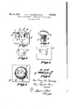
- Figure 1 is an enlarged side elevation of bo t or rivet in position connecting two plates
- Figure 2 is an enlarged plan view of a bolt or rivet as viewed rom underneath
- FIG. 3 is a view in perspective-of'the bolt or rivet, I
- Fi re 4 shows the upper plate prepared for t o reception of a bolt or rivet
- Figure 6 is a plate or washer embodying the rinciples outlined in the invention.
- e plates 1 and 2 are fastened together 35 by a be t or rivet like devices 3 having a head 4.- and two radial and diametrically opposite projections or wings .5 which register with de ressionsfi of the plate 2 (see Fig. 1).
- e up er plate 1 (see Figure 4) has a hole 7 which has shaped enlargements 8 diametrically opposite to each other. In dotted lines is shown the position to which the bolt or rivet like device 3 is rotated after being passed through the hole 7 and enlargements 8 in the plate 1.
- the centre point of the convexity 9 and of the hole 7 bein the same.
- the convexity 9 are formed the depressions 6, at an angle to the enlargements 8, and diametrically opposite to one another.
- the plate or washer 10 has an excrescence or convexity 11 through which is bored 9.
- hole 12 having shaped enlargements 13, and in the convexity 11 are formed depressions 14.
- the plates 1 and 2 are placed together so that the holes '7 and the enlargements 8 in the plates register, and the convexity 9 of the plate 2 is to the outside.
- the bolt or rivet like device 3 and its projections or wings 5 is then passed through the holes 7 and enlargements 8, until the lower face of the bolt head 4 abuts against the plate 1, and the wings 5 now extend beyond the outer surface of the plate 2.
- the bolt 3 is then revolved until the wings 5 are in alignment with the depression 6 in the convexity 9, into which they snap and lock the head of the bolt 3 firmly in position against the plate 1, the resilient material of which the plates 1 and 2 are made and the extra resiliency imparted by the convexity 9 causin the plate 2 to press against the wings 5 with a springlike action.
- the force exerted by the plate 2 upon the wings 5, depends upon the length of the bolt 3 from the underside of the head 4 to the bearsurface of the wings 5, and the extent to which the convexity 9 has been raised above the plane formed by the surface of the plate 2.
- the washer 10 of resilient material is used (see Figure 6).
- the plates to be joined together are provided with holes and enlargements such as are formed in plates 1. and the washer 10 is placed against one .of the plates with its convexity 11 and depressions 14 to- .wards the outside, and its hole 12 and en'- largements 13 registering with those of the plates to be fastened together.
- the procedure of 7 rting and adjusting the bolt is then set forth in the preceding description, the resiliency lacking in the plates or sheets being made good by the re s ilieney of the washer 10.
- the washer 10 may be whol y convex.
- Plates or sheets, one or more of a non-resilient material, and one or more of a res1l1 ent material can be fastened together by providing on one ofthe resilient plates or sheets the arran ement as shown provided for plate 2 in the rawings (see Fi ure 5).
- the bolt 3 may be provi ed with a saw-cut to take a screw-driver, and the wings-5 may or may not be integral with the bolt 3.
- the bolt were the bolt to be employed merely in cooperation with holes and enlar ements in the plates to be held together, the olt would tend to rotateand work loose if subjected to vibrations, and the wings might work back into the enlargements, and the plates would then come apart, which possibility is obviated in the present invention b the bolt being locked and resiliently held in position.
- VV hat we claim and desire to secure by Letters Patent is Means for fastenin plates together comprising a removable rivet like device formed with a head and having diametrically opposed lateral projections punched out of its shank at a given distance from said head, adapted to co-operate with over-lapping plates having registering holes for giving access to said rivet like device and its projec- 4 tions, and depressions on the outer surface of a convexity pressed out of the inner one of the plates at an angle to' the shaped enlargements whereby upon the bolt being passed through the registering holes and enlargements in the plates. and then rotated, the 'rojections lock with the depressions and the It is retained in position to clamp the plates together by the resilience produced by the convexity of the plate.
- a removable rivet like device formed with a head and having diametrically opposed lateral projections punched out of its shank at a given distance from said head, adapted to co-operate with over-lapping plates having
Landscapes
- Engineering & Computer Science (AREA)
- General Engineering & Computer Science (AREA)
- Mechanical Engineering (AREA)
- Connection Of Plates (AREA)
Description
May 10, 1932. e. F. JTDANDRIDGE ETAL 1,857,530
MEANS FOR THE FASTENING TOGETHER OF PLATES OR SHEETS Filed Aug. 8, 1929 Patented May 10, 1932 UNITED STATES PATENT OFFICE GEORGE FRANCIS JOHN DANDRIDGE, OF BEDFORD, AND GEORGE AUGUSTUS MOWER, OI
LONDON, ENGLAND MEANS FOR THE FASTENING TOGETHER OI PLATES OR SHEETS Application filed August 8, 1929, Serial No. 384,401, and in Great Britain October 1, 1928 This invention relates to means for the fastening together'of plates or sheets.
The invention consists broadly of a bolt or rivet formed with a head and having one or more lateral projections at a given distance. from said head, adapted to co-operate with overlapping plates having registering holes with suitablyshaped enlargements for permitting said bolt and its project ons to pass through and be turned. Depressions on the outer surface of one of the plates are preferably provided at an angle to the shaped enlargements, whereby'uponthe bolt being passed through the registering holes and enlargements in the plates and thenrotated, the projections lock with the depressions and the olt is retained in position. Reference is now directed to the accompanying drawings wherein Figure 1 is an enlarged side elevation of bo t or rivet in position connecting two plates,
Figure 2 is an enlarged plan view of a bolt or rivet as viewed rom underneath,
Figure 3 is a view in perspective-of'the bolt or rivet, I
Fi re 4 shows the upper plate prepared for t o reception of a bolt or rivet,
Figure 5 is a plan view of the outer surface of the lower plate and shows the plate prepared to receive a? bolt or rivet, and
Figure 6 is a plate or washer embodying the rinciples outlined in the invention.
e plates 1 and 2 are fastened together 35 by a be t or rivet like devices 3 having a head 4.- and two radial and diametrically opposite projections or wings .5 which register with de ressionsfi of the plate 2 (see Fig. 1).
e up er plate 1 (see Figure 4) has a hole 7 which has shaped enlargements 8 diametrically opposite to each other. In dotted lines is shown the position to which the bolt or rivet like device 3 is rotated after being passed through the hole 7 and enlargements 8 in the plate 1.
In the lower plate 2 (see Fi%1re 5) is a hole 7 having enlargements 8, t e hole and enlargements. being of the same dimensions as those of theplate. A disc-like convex excreseence or convexity 9 is pressed out of the ing.
plane of the plate 2 the centre point of the convexity 9 and of the hole 7 bein the same. In the convexity 9 are formed the depressions 6, at an angle to the enlargements 8, and diametrically opposite to one another.
In Figure 6 the plate or washer 10 has an excrescence or convexity 11 through which is bored 9. hole 12 having shaped enlargements 13, and in the convexity 11 are formed depressions 14.
The plates 1 and 2, of resilient material, are placed together so that the holes '7 and the enlargements 8 in the plates register, and the convexity 9 of the plate 2 is to the outside. The bolt or rivet like device 3 and its projections or wings 5 is then passed through the holes 7 and enlargements 8, until the lower face of the bolt head 4 abuts against the plate 1, and the wings 5 now extend beyond the outer surface of the plate 2. The bolt 3 is then revolved until the wings 5 are in alignment with the depression 6 in the convexity 9, into which they snap and lock the head of the bolt 3 firmly in position against the plate 1, the resilient material of which the plates 1 and 2 are made and the extra resiliency imparted by the convexity 9 causin the plate 2 to press against the wings 5 with a springlike action.
The force exerted by the plate 2 upon the wings 5, depends upon the length of the bolt 3 from the underside of the head 4 to the bearsurface of the wings 5, and the extent to which the convexity 9 has been raised above the plane formed by the surface of the plate 2.
When the plates or sheets to be joined together are not resilient (for instance 'of wood) the washer 10 of resilient material is used (see Figure 6). The plates to be joined together are provided with holes and enlargements such as are formed in plates 1. and the washer 10 is placed against one .of the plates with its convexity 11 and depressions 14 to- .wards the outside, and its hole 12 and en'- largements 13 registering with those of the plates to be fastened together. The procedure of 7 rting and adjusting the bolt is then set forth in the preceding description, the resiliency lacking in the plates or sheets being made good by the re s ilieney of the washer 10.
Instead of having an excrescence or convexitf' formed thereon, the washer 10 may be whol y convex.
Plates or sheets, one or more of a non-resilient material, and one or more of a res1l1 ent material can be fastened together by providing on one ofthe resilient plates or sheets the arran ement as shown provided for plate 2 in the rawings (see Fi ure 5).
The bolt 3 may be provi ed with a saw-cut to take a screw-driver, and the wings-5 may or may not be integral with the bolt 3. Were the bolt to be employed merely in cooperation with holes and enlar ements in the plates to be held together, the olt would tend to rotateand work loose if subjected to vibrations, and the wings might work back into the enlargements, and the plates would then come apart, which possibility is obviated in the present invention b the bolt being locked and resiliently held in position.
Although in the drawings only two plates are shown fastened together, and by only one bolt it will of course be understood that any number of plates may be attached together by the same bolts and many bolts used without departing from the spirit of the invention. Although in the present instance two wings on the bolts are shown co-operating with two depressions, it may be found convenient to provide one or a plurality of wings co-oper atin with depressions.
VV hat we claim and desire to secure by Letters Patent is Means for fastenin plates together comprising a removable rivet like device formed with a head and having diametrically opposed lateral projections punched out of its shank at a given distance from said head, adapted to co-operate with over-lapping plates having registering holes for giving access to said rivet like device and its projec- 4 tions, and depressions on the outer surface of a convexity pressed out of the inner one of the plates at an angle to' the shaped enlargements whereby upon the bolt being passed through the registering holes and enlargements in the plates. and then rotated, the 'rojections lock with the depressions and the It is retained in position to clamp the plates together by the resilience produced by the convexity of the plate. In witness whereof we aflix cur signatures.
GEORGE FRANCIS JOHN DANDRIDGE. GEORGE AUGUSTUS MOWER.
Applications Claiming Priority (2)
| Application Number | Priority Date | Filing Date | Title |
|---|---|---|---|
| GB1857530X | 1928-10-01 | ||
| GB3266228A GB325235A (en) | 1928-11-08 | 1928-11-08 | Improvements connected with removable rivet-like securing devices |
Publications (1)
| Publication Number | Publication Date |
|---|---|
| US1857530A true US1857530A (en) | 1932-05-10 |
Family
ID=26261503
Family Applications (1)
| Application Number | Title | Priority Date | Filing Date |
|---|---|---|---|
| US384401A Expired - Lifetime US1857530A (en) | 1928-10-01 | 1929-08-08 | Means for the fastening together of plates or sheets |
Country Status (1)
| Country | Link |
|---|---|
| US (1) | US1857530A (en) |
Cited By (14)
| Publication number | Priority date | Publication date | Assignee | Title |
|---|---|---|---|---|
| US2476339A (en) * | 1942-02-20 | 1949-07-19 | Opel Fritz Von | Fastening device |
| US2555291A (en) * | 1945-11-09 | 1951-05-29 | Illinois Tool Works | Fastener unit |
| US2556988A (en) * | 1946-12-21 | 1951-06-12 | Illinois Tool Works | Fastener device |
| US2626773A (en) * | 1950-09-11 | 1953-01-27 | Rodger J Backman | Shelf support |
| US2641814A (en) * | 1951-01-25 | 1953-06-16 | Tinnerman Products Inc | Separable fastener |
| US3198294A (en) * | 1963-12-26 | 1965-08-03 | Budd Co | Brake shoe fasteners |
| US3322507A (en) * | 1963-06-11 | 1967-05-30 | Union Carbide Corp | Apparatus for dissolving solid polymeric substances in a solvent |
| US3929311A (en) * | 1974-03-25 | 1975-12-30 | Knock N Lok | Supporting fastener |
| US3933011A (en) * | 1974-03-27 | 1976-01-20 | Digilio Philip | Ring with interchangeable setting |
| US4293984A (en) * | 1978-03-13 | 1981-10-13 | John Kaufmann, Jr. | Spring tension fastener |
| US4322064A (en) * | 1980-04-18 | 1982-03-30 | Michael Jarvis | Object-spacing tool and method thereof |
| US4353661A (en) * | 1978-07-06 | 1982-10-12 | Ruether Hubert | Exhibition/house furniture as well as play and sport equipment |
| USD460685S1 (en) | 2001-09-17 | 2002-07-23 | Annex Technology International Co. Ltd | Washer |
| US20050287903A1 (en) * | 2004-01-27 | 2005-12-29 | Troy Augborne | Integral toy vehicle display case and product package |
-
1929
- 1929-08-08 US US384401A patent/US1857530A/en not_active Expired - Lifetime
Cited By (14)
| Publication number | Priority date | Publication date | Assignee | Title |
|---|---|---|---|---|
| US2476339A (en) * | 1942-02-20 | 1949-07-19 | Opel Fritz Von | Fastening device |
| US2555291A (en) * | 1945-11-09 | 1951-05-29 | Illinois Tool Works | Fastener unit |
| US2556988A (en) * | 1946-12-21 | 1951-06-12 | Illinois Tool Works | Fastener device |
| US2626773A (en) * | 1950-09-11 | 1953-01-27 | Rodger J Backman | Shelf support |
| US2641814A (en) * | 1951-01-25 | 1953-06-16 | Tinnerman Products Inc | Separable fastener |
| US3322507A (en) * | 1963-06-11 | 1967-05-30 | Union Carbide Corp | Apparatus for dissolving solid polymeric substances in a solvent |
| US3198294A (en) * | 1963-12-26 | 1965-08-03 | Budd Co | Brake shoe fasteners |
| US3929311A (en) * | 1974-03-25 | 1975-12-30 | Knock N Lok | Supporting fastener |
| US3933011A (en) * | 1974-03-27 | 1976-01-20 | Digilio Philip | Ring with interchangeable setting |
| US4293984A (en) * | 1978-03-13 | 1981-10-13 | John Kaufmann, Jr. | Spring tension fastener |
| US4353661A (en) * | 1978-07-06 | 1982-10-12 | Ruether Hubert | Exhibition/house furniture as well as play and sport equipment |
| US4322064A (en) * | 1980-04-18 | 1982-03-30 | Michael Jarvis | Object-spacing tool and method thereof |
| USD460685S1 (en) | 2001-09-17 | 2002-07-23 | Annex Technology International Co. Ltd | Washer |
| US20050287903A1 (en) * | 2004-01-27 | 2005-12-29 | Troy Augborne | Integral toy vehicle display case and product package |
Similar Documents
| Publication | Publication Date | Title |
|---|---|---|
| US1857530A (en) | Means for the fastening together of plates or sheets | |
| US2476339A (en) | Fastening device | |
| US1666783A (en) | Locking device | |
| US1741077A (en) | Nut lock | |
| US2469312A (en) | Screw locking device | |
| US2337457A (en) | Fastening device | |
| DE2325241A1 (en) | DETACHABLE PANEL CONNECTOR | |
| US2688507A (en) | Snap fastener for box covers | |
| US1930783A (en) | Fastening device | |
| US1619757A (en) | Lock bolt | |
| US4069997A (en) | Waste receptacle cam lock with locking projection | |
| US2421204A (en) | Eastener for adjoining sheets or plates | |
| US1792594A (en) | Screen-repairing device | |
| US3136517A (en) | Adjustable warp-resisting leg holder plate | |
| US2612927A (en) | Blind fastener | |
| US2911575A (en) | Selenium and like rectifier stack | |
| US1896964A (en) | Rail splice | |
| JPS6215609U (en) | ||
| US4825613A (en) | Non rotatable apparatus for securing roofing insulation blocks and an outer membrane | |
| US1386092A (en) | Washer | |
| US2025686A (en) | Turn operated fastener and installation | |
| US1520032A (en) | Nut lock | |
| US2527783A (en) | Fastening device | |
| US3575079A (en) | Quick release fastener | |
| EP0612492A1 (en) | Fixing element to prevent a mat from slipping |