US1857513A - Door latch - Google Patents
Door latch Download PDFInfo
- Publication number
- US1857513A US1857513A US41987A US4198725A US1857513A US 1857513 A US1857513 A US 1857513A US 41987 A US41987 A US 41987A US 4198725 A US4198725 A US 4198725A US 1857513 A US1857513 A US 1857513A
- Authority
- US
- United States
- Prior art keywords
- handle
- rotatable
- bolt
- link
- door
- Prior art date
- Legal status (The legal status is an assumption and is not a legal conclusion. Google has not performed a legal analysis and makes no representation as to the accuracy of the status listed.)
- Expired - Lifetime
Links
- 239000011521 glass Substances 0.000 description 8
- 238000010276 construction Methods 0.000 description 3
- 241000333688 Wormaldia moesta Species 0.000 description 2
- 239000002184 metal Substances 0.000 description 2
- 241000257303 Hymenoptera Species 0.000 description 1
- 230000000994 depressogenic effect Effects 0.000 description 1
- 230000002452 interceptive effect Effects 0.000 description 1
- 229920000136 polysorbate Polymers 0.000 description 1
Images
Classifications
-
- E—FIXED CONSTRUCTIONS
- E05—LOCKS; KEYS; WINDOW OR DOOR FITTINGS; SAFES
- E05B—LOCKS; ACCESSORIES THEREFOR; HANDCUFFS
- E05B85/00—Details of vehicle locks not provided for in groups E05B77/00 - E05B83/00
- E05B85/20—Bolts or detents
- E05B85/22—Rectilinearly moving bolts
-
- Y—GENERAL TAGGING OF NEW TECHNOLOGICAL DEVELOPMENTS; GENERAL TAGGING OF CROSS-SECTIONAL TECHNOLOGIES SPANNING OVER SEVERAL SECTIONS OF THE IPC; TECHNICAL SUBJECTS COVERED BY FORMER USPC CROSS-REFERENCE ART COLLECTIONS [XRACs] AND DIGESTS
- Y10—TECHNICAL SUBJECTS COVERED BY FORMER USPC
- Y10S—TECHNICAL SUBJECTS COVERED BY FORMER USPC CROSS-REFERENCE ART COLLECTIONS [XRACs] AND DIGESTS
- Y10S292/00—Closure fasteners
- Y10S292/67—Vehicle door latches free of sash or pane
-
- Y—GENERAL TAGGING OF NEW TECHNOLOGICAL DEVELOPMENTS; GENERAL TAGGING OF CROSS-SECTIONAL TECHNOLOGIES SPANNING OVER SEVERAL SECTIONS OF THE IPC; TECHNICAL SUBJECTS COVERED BY FORMER USPC CROSS-REFERENCE ART COLLECTIONS [XRACs] AND DIGESTS
- Y10—TECHNICAL SUBJECTS COVERED BY FORMER USPC
- Y10T—TECHNICAL SUBJECTS COVERED BY FORMER US CLASSIFICATION
- Y10T292/00—Closure fasteners
- Y10T292/08—Bolts
- Y10T292/096—Sliding
- Y10T292/1014—Operating means
- Y10T292/1015—Link and lever
Definitions
- This invention relates generally to latches designed particularly for use with vehicle doors and consists of certain novel features of construction, combinations and arrangements of parts as will be more fully described and particularly pointed out in the appended claims.
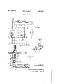
- Figure 1 is a fragmentary side elevation of d a door with the latch mechanism embodying my invention applied thereto.
- FIG. 2 is an enlarged horizontal sectional view through the latch.
- Figure 3 is a detail perspective view ofthe link.
- the numeral 1 designates a door, preferably of a vehicle body, having a pillar 2 that is connected at its inner and outer edges to suitable sheet metal panels 3 and 4 respectively and that supports a channel-shaped-strip 5 which constitutes a runway for a vertically movable glass window panel 6'.
- the pillar 2 is preferably constructed of sheet metal and v is substantially L-shaped in cross section, while the channel-shapeds'trip 5 is preferably secured directly to the inner face of the pillar and holds a suitable felt guide 7 for the window panel 6.
- a standard latch 9 having a latching bolt 10 which is adapted to engage a suitable keeper (not shown) on a door jamb when the door is closed.
- Any suitable means such as the I' spindle 11 and roll-back 12 may be employed for retracting the bolt 10 against the tension of a suitable spring- (not shown) lfor normally holding the bolt in projected position.
- I preferably provide a U- shaped link 13 that is adapted to be operated by a suitable handle 143for actuating the rollback 12.
- the base 15 of the U- ⁇ shaped link is preferably disposed upon the .outer face of the pillar 2. while the arms 16 and .17 respectively extend inwardly through suitable slots ⁇ 18 and 19 respectivelyupon op- 50 posite sides of the channel-shaped runway 5.
- the lU-shaped link is a one-piece construction having arms 16 and 17 integral with the base extending therebe tween.
- the inner arm 16 is preferably provided with aI lateral extension 20 that is preferably square shape in cross section and that fits Within the square opening 21 in the hubof the roll-back, while the outer arm 17 is preferably provided with a square opening.;v
- This handle may be any suitable construction but has an escutcheon plate 24 mounted -on the outer panel 4 of the door.
- I preferably provide a suitable coil spring 25 that is sleeved upon the shankV 23 of the handle 14 between the hub 26 there' ⁇ of and the outer arm 17 of the link.
- this spring325 will normally hold the extension 20 of the inner arm 16 inoperative engagement with the roll-back 12 and will ef-y fectlvely prevent the parts from rattling.
- a suitable cover 27 may bese cured to the outer face of the pillar 2 to conceal the link 13.
- a latch the combination with a latching bolt, of a roll-back for actuating the bolt and a shafted operating handle, of a onepiece link operatively connecting the rollback and handle, said link including a transversely extending base. and arm formed integral with one end of said base, an aperture in the end of said ar-m for receiving the shaft of the handle, .an arm formed integral with the other end of said base and a projection at the end of said last mentioned arm for engaging the rollback.
- a latching mechanism the combination of a latch bolt, a remotely positioned rotatable shafthandle for operating said bolt and an operating connection between said handle and bolt comprising an integral offset link having one end connected to the shaft of said handle and rotatable on the axis of the shaft and the other end rotatably mounted in the projected line of said handle shaft xs and operably connected to said latch 10.
- a latching mechanism In a latching mechanism, the combination of a latch bolt, a rotatable cam for operating said bolt, a rotatable handle for remotely operating said cam spaced apart 'from said cam and rotatable on the projected line of the axis of said cam andan operating connection between said cam and handle comprising an integral U-Shaped link having its respective ends joined to said handle and said cam.
Landscapes
- Lock And Its Accessories (AREA)
- Window Of Vehicle (AREA)
Description
May l0, 1932. M. w. MoEsTA DOOR LATCH Filed July 7 1925 Panarea May 1o, 1932 UNITED "STATES PATENT orifice MARVIN W. MOESTA, OF DETROIT, MICHIGAN, ASSIGNOR TO MURRAY BODY CORPORA- TION, 'OF DETROIT, MICHIGAN, A CORPORATION 0F MICHIGAN DOOR LATCH Application led July 7,
This invention relates generally to latches designed particularly for use with vehicle doors and consists of certain novel features of construction, combinations and arrangements of parts as will be more fully described and particularly pointed out in the appended claims.
Figure 1 is a fragmentary side elevation of d a door with the latch mechanism embodying my invention applied thereto.
- Figure 2 is an enlarged horizontal sectional view through the latch. y
Figure 3 is a detail perspective view ofthe link.
Referring now to` the drawings, the numeral 1 designates a door, preferably of a vehicle body, having a pillar 2 that is connected at its inner and outer edges to suitable sheet metal panels 3 and 4 respectively and that supports a channel-shaped-strip 5 which constitutes a runway for a vertically movable glass window panel 6'. As shown, the pillar 2 is preferably constructed of sheet metal and v is substantially L-shaped in cross section, while the channel-shapeds'trip 5 is preferably secured directly to the inner face of the pillar and holds a suitable felt guide 7 for the window panel 6.
Mounted upon the inner panel 3, preferably within a depressed portion 8 thereof, is a standard latch 9 having a latching bolt 10 which is adapted to engage a suitable keeper (not shown) on a door jamb when the door is closed. Any suitable means such as the I' spindle 11 and roll-back 12 may be employed for retracting the bolt 10 against the tension of a suitable spring- (not shown) lfor normally holding the bolt in projected position.
In order that the bolt 10 may be operated from the outside of the door without inten fering with the vertical movement of the glass panel 6, I preferably provide a U- shaped link 13 that is adapted to be operated by a suitable handle 143for actuating the rollback 12. As shown, the base 15 of the U- `shaped link is preferably disposed upon the .outer face of the pillar 2. while the arms 16 and .17 respectively extend inwardly through suitable slots`18 and 19 respectivelyupon op- 50 posite sides of the channel-shaped runway 5.
1925. serial m. 41,9831.
It will be noted that the lU-shaped link is a one-piece construction having arms 16 and 17 integral with the base extending therebe tween. The inner arm 16 is preferably provided with aI lateral extension 20 that is preferably square shape in cross section and that fits Within the square opening 21 in the hubof the roll-back, while the outer arm 17 is preferably provided with a square opening.;v
22 that receives the square shank 23 of the outside handle 14. This handle may be any suitable construction but has an escutcheon plate 24 mounted -on the outer panel 4 of the door. v To prevent the link 13 moving transversely of the door, I preferably provide a suitable coil spring 25 that is sleeved upon the shankV 23 of the handle 14 between the hub 26 there'` of and the outer arm 17 of the link. Thus this spring325 will normally hold the extension 20 of the inner arm 16 inoperative engagement with the roll-back 12 and will ef-y fectlvely prevent the parts from rattling.
If desired, a suitable cover 27 may bese cured to the outer face of the pillar 2 to conceal the link 13. Thus, from the foregoing description, it will be readily apparent that standard latch mechanism may be readily mounted and opv erated upon door pillars having relatively vsmall cross'sectionslwithout interfering with the movement of the glass panels,y consequently a wider glass panel may be employed 'and the vision of theoccu ants of the vehicle is materially increase i While it is believed that `from the foregoing description, the nature and advantages of the invention will be readily apparent, I
desire to have it understood that I do not limit myself to what is herein shown and delscribed, and thatsuch changes may be re- 35. 1- common to the axis ofrotation of the rollend thereof, one of said arms directly connected to the handle and the other ofl said arms directly connected to the roll-back, said link being rotatable on the axis of the handle.
2. In a latch, the combination with a latching bolt, of a roll-back for actuating the bolt and a shafted operating handle, of a onepiece link operatively connecting the rollback and handle, said link including a transversely extending base. and arm formed integral with one end of said base, an aperture in the end of said ar-m for receiving the shaft of the handle, .an arm formed integral with the other end of said base and a projection at the end of said last mentioned arm for engaging the rollback.
3. The combination in a latch of a latching bolt, a roll-back for actuating said bolt, a hub on which said roll-back rotates, an operating handle, a rotatable shaft for said handle in axial alignment with the hub of the rollback and a one-piece offset transversely extending link connected at its respective ends with the hub of the roll-back and with thenshaft of the handle.
4. The combination in a latch of a latching bolt, a rotatable roll-'back for actuating said bolt, an operating handle rotatable on an axis common to the axis of rotation of the rollback and a one-piece offset link disposed between said parts operatively joining the parts and rotatable on their common axes.
5. The combination in a latch of a latching bolt, a rotatable roll-back for actuating said bolt, an operating handle rotatable on an axis back and spaced therefrom and a transversely extending one-piece link operatively connecting. said parts and rotatable on their common axes, said link having an integral central portion which rotates in an arc offset from theaxis of rotation of the parts.
6. The combination in a latch of a latchingy bolt, a rotatable roll-back for actuating said bolt, an operating handle rotatable on an axis common to that of the roll-back and spaced therefrom and a transversely extending onepiece oi'set link operatively connecting the parts and journaled at their common axes, the offset portion of said link rotatable yin an arc spaced from the common axes of rotation of the parts. Y
7. The combination with a door having a runway for a movable glass panel, of latch mechanism carried by the door having a latch bolt, a. rotatable roll-back upon one side of the runway, a rotatable operating handle on the other side of the runway, saidyroll-bac'k and handle being rotatable on a commonaxis extending transverselyof the door through the runway and a one-piece link operatively connecting the roll-back and handle and ro- 8,. The combination with a door having a runwaytor a movable glass panel, of latchthe runway, a rotatable operating handle on the other side of the runway, said roll-back and handle being rotatable on a common axis extending transversely of the door through the runway and a one-piece link operatively f connecting the parts, and rotatable on their common axes, said link having an arm attached to the roll-back, another arm attached to the handle and an integral central portion joining the arms and oli'set to swing in an arc beyond the outer edge of the runway.
9. In a latching mechanism, the combination of a latch bolt, a remotely positioned rotatable shafthandle for operating said bolt and an operating connection between said handle and bolt comprising an integral offset link having one end connected to the shaft of said handle and rotatable on the axis of the shaft and the other end rotatably mounted in the projected line of said handle shaft xs and operably connected to said latch 10. In a latching mechanism, the combination of a latch bolt, a rotatable cam for operating said bolt, a rotatable handle for remotely operating said cam spaced apart 'from said cam and rotatable on the projected line of the axis of said cam andan operating connection between said cam and handle comprising an integral U-Shaped link having its respective ends joined to said handle and said cam.
11. The combination with a door having a runway for a movable glass panel of latch mechanism carried by the door having a latching bolt disposed on one side of the runway, a. rotatable handle for operating said bolt disposed on the opposite side of the runway, the axis of rotation of said handle extending transversely of the door through the runway, and an operating connection between said handle and bolt'comprising a one-piece oilset link extending transversely of the door outside the runway and rotatable on the projected axis of said handle and mounting a cam for actuating the latch bolt.
In testimony whereof I aiiix my signature.
MARVIN IV. lWOESTA.
tatable on their common axes, said link being v offset to extend around the outer side of the glass runway.
Priority Applications (1)
| Application Number | Priority Date | Filing Date | Title |
|---|---|---|---|
| US41987A US1857513A (en) | 1925-07-07 | 1925-07-07 | Door latch |
Applications Claiming Priority (1)
| Application Number | Priority Date | Filing Date | Title |
|---|---|---|---|
| US41987A US1857513A (en) | 1925-07-07 | 1925-07-07 | Door latch |
Publications (1)
| Publication Number | Publication Date |
|---|---|
| US1857513A true US1857513A (en) | 1932-05-10 |
Family
ID=21919432
Family Applications (1)
| Application Number | Title | Priority Date | Filing Date |
|---|---|---|---|
| US41987A Expired - Lifetime US1857513A (en) | 1925-07-07 | 1925-07-07 | Door latch |
Country Status (1)
| Country | Link |
|---|---|
| US (1) | US1857513A (en) |
-
1925
- 1925-07-07 US US41987A patent/US1857513A/en not_active Expired - Lifetime
Similar Documents
| Publication | Publication Date | Title |
|---|---|---|
| US2270559A (en) | Door lock | |
| US8967679B2 (en) | Vehicle door latch | |
| CN105658890B (en) | latch for a door of a motor vehicle | |
| US3743336A (en) | Frictionless cabinet latch | |
| US7431357B2 (en) | Exterior door handle with minimum surface intrusion | |
| US2468644A (en) | Lock mechanism | |
| US8016329B2 (en) | Latch | |
| CN105003133B (en) | Latches for doors of motor vehicles | |
| DE502005002441D1 (en) | LOCK FOR DOORS OR FLAPS ON VEHICLES | |
| EP3575521A1 (en) | Vehicle door latch device | |
| US8250889B2 (en) | Compact power lock | |
| US2773376A (en) | Door latch and lock | |
| US3587259A (en) | Latch operating arrangement | |
| US2435987A (en) | Automobile door latch mechanism | |
| US1857513A (en) | Door latch | |
| US2835526A (en) | Door latch | |
| US6454325B1 (en) | Closure hand lever that can be used in confined environments | |
| US2581838A (en) | Door lock | |
| US10138657B2 (en) | Motor vehicle door lock | |
| US2955865A (en) | Automobile door latch | |
| US2240865A (en) | Door handle assembly | |
| US20210164268A1 (en) | Motor vehicle door lock | |
| US2355449A (en) | Outside door handle assembly | |
| US2637580A (en) | Door lock | |
| US2667778A (en) | Lock mechanism |