US1857093A - Window sash and muntin construction - Google Patents
Window sash and muntin construction Download PDFInfo
- Publication number
- US1857093A US1857093A US383189A US38318929A US1857093A US 1857093 A US1857093 A US 1857093A US 383189 A US383189 A US 383189A US 38318929 A US38318929 A US 38318929A US 1857093 A US1857093 A US 1857093A
- Authority
- US
- United States
- Prior art keywords
- plate
- glass
- muntin
- sash
- construction
- Prior art date
- Legal status (The legal status is an assumption and is not a legal conclusion. Google has not performed a legal analysis and makes no representation as to the accuracy of the status listed.)
- Expired - Lifetime
Links
- 238000010276 construction Methods 0.000 title description 13
- 239000011521 glass Substances 0.000 description 38
- 239000002184 metal Substances 0.000 description 18
- 229910052751 metal Inorganic materials 0.000 description 18
- 239000011324 bead Substances 0.000 description 3
- 229910000746 Structural steel Inorganic materials 0.000 description 1
- 238000000034 method Methods 0.000 description 1
- 238000012986 modification Methods 0.000 description 1
- 230000004048 modification Effects 0.000 description 1
- 239000003351 stiffener Substances 0.000 description 1
- 238000003466 welding Methods 0.000 description 1
Images

Classifications
-
- E—FIXED CONSTRUCTIONS
- E06—DOORS, WINDOWS, SHUTTERS, OR ROLLER BLINDS IN GENERAL; LADDERS
- E06B—FIXED OR MOVABLE CLOSURES FOR OPENINGS IN BUILDINGS, VEHICLES, FENCES OR LIKE ENCLOSURES IN GENERAL, e.g. DOORS, WINDOWS, BLINDS, GATES
- E06B3/00—Window sashes, door leaves, or like elements for closing wall or like openings; Layout of fixed or moving closures, e.g. windows in wall or like openings; Features of rigidly-mounted outer frames relating to the mounting of wing frames
- E06B3/68—Window bars
Definitions
- This invention relates to a construction for window sashes, whereby the sashes can be formed out of sheet metal and assembled complete with muntins and glass stops, using a a perspective showing details of construction at the top, or meeting rail, of the lowersash;
- Fig. is a perspective showing details of construction at the bottom rail of the lower sash
- Fig. 6 is a view from the inside showing the face oi. the top portion of the upper sash
- Fig. '7 is a section on line 77 of Fig. 6
- Fig. 8 is a view from the inside showing portions of the face of the lower sash;
- Fig. 9 is a section through the top rail of the lower sash;
- Fig. 10 is a section on line 10-10 of Fig.
- Fig. 11 is a perspective view showing the way the muntin bars are assembled and attached to side rails of the sash;
- Fig. 12 is a pers )ective showing further details of the assem )ling of the muntin bars and their attachmentto the meeting rail of the upper sash;
- Fig. 13 is a section on line 1313 of Fig. 11
- Fig. 14 is a section on line 1414 of Fig. 13;
- Fig. 15 is a sectional view corresponding to Fig. 14 showing a slight modification.
- the side rail 10 of the upper sash is formed of sheet metal bent back on itself with a clearance between the two -faces to form apocket 12.
- the inside face is bent inwardly at 14 to form a glass rabbet and mav be shaped to form an ornamental head 16 which also serves as a stiffener.
- the cut edges of the plate are bent inwardly on themselves, as indicated at 18, to give the part a finish.
- Across the top a.plate 20 is provided, having an outwardly bent flange 21, which plate extends into the pocket 12 where it is spot welded, as indicated at 22. It is understood that this plate 20 extends all the way across the top of the window and is connected in a similar manner to both side rails.
- a plate 24 is provided, which is bent inwardly and upwardly to form a meeting rail hook 26.
- a member 28 is welded tothe plate 24 and is bent inwardly and upwardly to bring its edge in line with the inside edge of side rail 10.
- the ornamental and stiffening bead 16 of the side rail 10 is continued down until it meets the inwardly extending portion of the plate 24 so that a squared joint is formed between the inner edge 28 and the inner edge of plate 10.
- a rectangular frame is formed for the upper sash. provided with glass rabbets at the bottom and sides. If no muntin bars are used a single piece of glass is slipped down from the. top alongside of plate 20 into these rabbets and set with putty. as usual.
- a member 30 is provided of exactly the same cross-section as the side rails 10. The member 30 slips down over plate 20 with plate 20 extending up into the pocket 32 corresponding to the side railpocket 12.
- the corner joints between the side rail member 10 and the top rail member 30 are preferably lnitered.
- a pole socket 34 is attached at the middle of the window by two screws which extend into the plate 20 and hold member 30 in place.
- the construction of the lower sash is very similar to that of the upper sash though it necessarily differs in certain details.
- the side rails 36 are the same cross-section as the side rails 10, having similar pockets 38.
- the bottom rail 40 is also of similar cross-section except that the pocket 42 (see Fig. 10) is of greater depth than the pocket 38 so that the whole piece is wider than the side rails.
- an angle iron 44 is inserted in each corner extending into the pockets 38 and 42, where it is spot welded in place.
- a member 46 which fits directly under the bottom glass r'abbet, is welded to the bottom rail 40.
- a weather strip such as is described in my co-pending application Serial No.37 5,384, filed July 2nd, 1929, is tobe attached to the bottom rail, this can be done by welding on the outside of the rail40 a hook 48 under which the-weather strip 50 may be slipped endwise.
- a plate 52 extends into the pockets 38 where it is welded in place.
- the plate 52 is bent outwardly and down to form a meeting railhook 54 which interlocks with-the meeting rail 26.
- a rectangle is formed having glass rabbets in the sides and bottom into which the glass can he slipped past the plate 52.
- the muntins here used are shown in the form of hot rolled bars havin side plates 62 and 64 and a connecting we 66 to form an H. If desired, the muntins may also be provided with an additional head 68 ornamenting the inner face.
- the method of attachment of the vertical muntins to the upper sash is shown in Figs. 2 and 12. At the bottom, the head 68, face plate 64 and web 66 are cut away so that these portions are in line with the upper edge of member 28. Face plate 62 continues down on the outside of plate 24, where it is welded in place. At the upper end of the upper sash, plate 20 is notched out, as shown in Fig. 2, to receive face plate 62 of the muntin bar.
- the muntin bar has face plate 62, web 66 and face plate 64 cut off at the same length and bead 68 extends up so that its upper end will contact with head 70 of cover plate 30. In Fig. .1, these parts are shown in assembled relation. If no horizontal muntins are used, three pieces of glass can be slid in vertically in the same way as one piece is inserted when there are no muntins. v
- horizontal muntins such as indicated at 71 and 73, are called for, I arrange so that these can be put in lace by vertical movement as shown in Figs. 11 and 15.
- a cli 72 is welded in place in the glass-pocket o the side rails 10 but toward the outside of the window.
- the muntin bars 71 (see Fig. 11) have the two side plates 62 and 64 cut to butt against the folded inner edges of the side rails 10, while the web 66 extendsinto the glass-pocket where it is engaged by cli 72.
- the head 68 extends over to meet ead 16.
- the side plates, web and bead of the horizontal pieces are cut to meet the corresponding parts of the vertical muntins.
- the pole socket 34 is removed, permitting the removal of cover plate 30.
- Thethree lower lights of glass are then slipped down in place and set in putty.
- the two horizontal muntins 71 that are at the sides are then inserted diagonally with their webs 66 in the clip 72, and the portions adjacent the vertical muntins are pushed down into lace.
- the central horizontal muntin 73 can e put in place by direct-vertical movement.
- I prefer to use a square plate 74 which is screwed on the outside of the vertical muntin bar. The corners of this plate are stamped in, as indicated at 76 to lock "the horizontal muntins against vertlcal movement.
- the muntins are attached in a similar manner.
- the outer plate 62 of the vertical muntin bar is welded to the outside face of plate 52.
- clips similar to clip 72 are used and the head 68 is spot welded to the bottom rail 40 so that the appearance along the bottom rail is similar to that along the side rails.
- a window-frame comprisin side and bottom members formed with g ass channels, a plate connecting the upper parts of such side members so that-a piece of glass may be slipped by such plate into said channels and a folded cover plate adapted to he slipped over said connecting plate to hold theupper edge of the glass, said cover comletely hiding said late upon the inside and adapted by siiape and size to be positioned upon the plate to complete the frame with the contour of the side members so that the cover is the visible portion of the inside of the top.
- each side member is formed of a piece of sheet metal bent to form a sash plate and the glass channel.
- a window comprising side members having glass channels, vertical muntins between the side members having glass channels, means for holding the ends of the glass channels and side members in spaced relation, while leaving one end of such channels open to receive glass, means for closing such end of said channels, horizontal muntin members adapted to be interlocked with the side members and vertical muntins by a movement in the plane of the vertical muntins and having a component along the line of such vertical muntins, and means for holdlng such horizontal muntins against vertical movement.
- a metal window frame formed with side members of sheet metal each bent back upon itself so as to form a fold and a glass rabbet, a bottom member having a glass rabbet, a cross plate permanently joining the top of said sides with ends extending lnto the said folds, and a removable cover for said cross plate formed of metal of substantially the same thickness as said side members and bent to form a glass rabbet adapted to rest upon said plate, said plate being adapted to unite the inside surfaces of said side members and said cover and hold them in substantially the same plane.
- a metal window frame comprising side and bottom members permanently connected, a cross plate permanently connecting said side members, a vertical muntin bar formed with an inner and outer face plate and permanently connected with said bottom member and cross plate, and a removable folded cover for said cross plate folded so as to form a glass rabbet and adapted to be slipped over said cross plate, the inner face plate of said muntin bar being projected upwardly so as to hold a portion of the cover in position between itself and said cross plate, all of said permanently connected members being so positioned as to allow glass-to be inserted when the cover is removed.
- a sheet metal window frame comprising side members of integral sheets each folded back upon itself to form a stiffening head on the inside portion and a glass channel, a connecting bottom member, a top connective plate entering the folds of the side members, and a removable folded cover for said top plate adapted to be slipped over and rest upon said top plate and shaped to form a glass channel for the top of the glass, said cover being formed with an inside portion substantially similar in cross section to the inside portion of said side members, said top connective plate being adapted to align the inside portions of the cover and the sides.
- a metal window sash folded sheet metal sides formed with a glass channel, a bottom connective member provided with a glass channel, a connective plate uniting the top of said sides so formed as to allow glass to be slipped into the glass channels, and a removable cover for said plate adapted to hold glass in place and to fill out the structural form of the window, said plate being adapted to align the cover with the sides.
- a bottom window sash formed of sheet metal comprising sash members of integral sheet metal folded back upon themselves so as to form glass rabbets, a bottom member folded back upon itself to form a glass rabbet, said side and bottom members being permanently connected, a top member formed of a strip of sheet metal, the ends of which enter into the folds of said side members and a portion of which is bent outwardly and downwardly to form a meeting rail, said top member being adjacent but substantially out of the plane of said glass rabbets, a cover plate for said top member bent so as to form a glass rabbet with said top member, and means to removably position said cover plate upon said top member.
- a top window sash formed of sheet metal comprising side members formed of a sheet of metal each bent back upon itself so as to form a glass rabbet, a bottom member joining said side members formed of an integral plate bent so that it is adapted to form a meeting rail and being connected to said side members, a member welded upon said bottom member adapted to form a glass rabbet with said bottom member, a top plate permanently connecting said side members and having ends extending into the folds of the latter. and an integral piece of folded sheet metal formed so that it may be slipped over said plate and so that it-and a part of said'plate form a glass rabbet and means to removably position said folded piece of sheet metal in place over said plate.
Landscapes
- Engineering & Computer Science (AREA)
- Civil Engineering (AREA)
- Structural Engineering (AREA)
- Securing Of Glass Panes Or The Like (AREA)
Description
y 1932- H. E. CAMPBELL 1,857,093
WINDOW SASH AND MUNTIN CONSTRUCTION Filed Aug. 3, 1929 4 Sheets-Sheet 1 INVENTOR /%7; (am 959% m im Wm @QWM ATTORNEYS May 3, 1932.
WINDOW SASH AND MUNTIN CONSTRUCTION H. E. CAMPBELL 1,857,093
Filed Aug. 3, 1929 4 Sheets-Sheet 2 I I g I I I INVENTOR WMNBIMMO ATTORNEYJ y 1932- H. E. CAMPBELL 1,857,093
WINDOW SASH AND MUNTIN CONSTRUCTION Filed Aug. 3, 1929 4 Sheets-Sheet 3 65mph fi/z L ATTORN EYS y 1932- H. E. CAMPBELL 57,093
WINDOW SASH AND MUNTIN CONSTRUCTION Filed Aug. 3, 192.9 4 Sheets-Sheet 4 INVENTOR Y WMM WLL A TORNEYS Patented May 3, 1932 UNITED STATES PATENT OFFICE HARRY E. CAMPBELL, 0F BALTIMORE, MARYLAND, ASSIGNOR TO CAMIBELL METAL WINDOW CORPORATION, OF BALTIMORE, MARYLAND, A CORPORATION OF MARY- LAND WINDOW SASH AND MUNT'IN CONSTRUCTION Application filed August a, 1929. Serial No. 383,189.
This invention relates to a construction for window sashes, whereby the sashes can be formed out of sheet metal and assembled complete with muntins and glass stops, using a a perspective showing details of construction at the top, or meeting rail, of the lowersash; Fig. is a perspective showing details of construction at the bottom rail of the lower sash Fig. 6 is a view from the inside showing the face oi. the top portion of the upper sash; Fig. '7 is a section on line 77 of Fig. 6; Fig. 8 is a view from the inside showing portions of the face of the lower sash; Fig. 9 is a section through the top rail of the lower sash; Fig. 10 is a section on line 10-10 of Fig. 8; Fig. 11 is a perspective view showing the way the muntin bars are assembled and attached to side rails of the sash; Fig. 12 is a pers )ective showing further details of the assem )ling of the muntin bars and their attachmentto the meeting rail of the upper sash; Fig. 13 is a section on line 1313 of Fig. 11 Fig. 14 is a section on line 1414 of Fig. 13; Fig. 15 is a sectional view corresponding to Fig. 14 showing a slight modification.
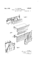
As shown in Fig. 2, the side rail 10 of the upper sash is formed of sheet metal bent back on itself with a clearance between the two -faces to form apocket 12. The inside face is bent inwardly at 14 to form a glass rabbet and mav be shaped to form an ornamental head 16 which also serves as a stiffener. The cut edges of the plate are bent inwardly on themselves, as indicated at 18, to give the part a finish. Across the top a.plate 20 is provided, having an outwardly bent flange 21, which plate extends into the pocket 12 where it is spot welded, as indicated at 22. It is understood that this plate 20 extends all the way across the top of the window and is connected in a similar manner to both side rails.
At the bottom of the upper sash a plate 24 is provided, which is bent inwardly and upwardly to form a meeting rail hook 26. The ends of plate 24, like the ends of plate 20,-extend into the pocket 12 of the side rails and are spot welded in place. In order to form a glass rabbet at the bottom rail of the upper sash a member 28 is welded tothe plate 24 and is bent inwardly and upwardly to bring its edge in line with the inside edge of side rail 10. As shown in Figs. 1 and 3, the ornamental and stiffening bead 16 of the side rail 10 is continued down until it meets the inwardly extending portion of the plate 24 so that a squared joint is formed between the inner edge 28 and the inner edge of plate 10.
By the construction thus far described a rectangular frame is formed for the upper sash. provided with glass rabbets at the bottom and sides. If no muntin bars are used a single piece of glass is slipped down from the. top alongside of plate 20 into these rabbets and set with putty. as usual. To hold the glass in place a member 30 is provided of exactly the same cross-section as the side rails 10. The member 30 slips down over plate 20 with plate 20 extending up into the pocket 32 corresponding to the side railpocket 12. The corner joints between the side rail member 10 and the top rail member 30 are preferably lnitered. A pole socket 34 is attached at the middle of the window by two screws which extend into the plate 20 and hold member 30 in place.
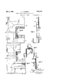
The construction of the lower sash is very similar to that of the upper sash though it necessarily differs in certain details. As shown in Fig. 5, the side rails 36 are the same cross-section as the side rails 10, having similar pockets 38. The bottom rail 40 is also of similar cross-section except that the pocket 42 (see Fig. 10) is of greater depth than the pocket 38 so that the whole piece is wider than the side rails. To connect the bottom rail 40 with the side rails 36 an angle iron 44 is inserted in each corner extending into the pockets 38 and 42, where it is spot welded in place. To provide a lift rail for the lower sash a member 46, which fits directly under the bottom glass r'abbet, is welded to the bottom rail 40. If a weather strip, such as is described in my co-pending application Serial No.37 5,384, filed July 2nd, 1929, is tobe attached to the bottom rail, this can be done by welding on the outside of the rail40 a hook 48 under which the-weather strip 50 may be slipped endwise. x
At the top' of the lower sash a plate 52 extends into the pockets 38 where it is welded in place. The plate 52 is bent outwardly and down to form a meeting railhook 54 which interlocks with-the meeting rail 26. With this construction, as in the case of the upper sash, a rectangle is formed having glass rabbets in the sides and bottom into which the glass can he slipped past the plate 52.
held in place beneath to cover plate 56.
In conjunction with the sashes which have been described, I also show a new form of muntin bar construction but it is to be understood that the sash can be used without this muntin bar, and that this muntin bar v construction may be used with other forms of sashes.
The muntins here used are shown in the form of hot rolled bars havin side plates 62 and 64 and a connecting we 66 to form an H. If desired, the muntins may also be provided with an additional head 68 ornamenting the inner face. The method of attachment of the vertical muntins to the upper sash is shown in Figs. 2 and 12. At the bottom, the head 68, face plate 64 and web 66 are cut away so that these portions are in line with the upper edge of member 28. Face plate 62 continues down on the outside of plate 24, where it is welded in place. At the upper end of the upper sash, plate 20 is notched out, as shown in Fig. 2, to receive face plate 62 of the muntin bar. The muntin bar has face plate 62, web 66 and face plate 64 cut off at the same length and bead 68 extends up so that its upper end will contact with head 70 of cover plate 30. In Fig. .1, these parts are shown in assembled relation. If no horizontal muntins are used, three pieces of glass can be slid in vertically in the same way as one piece is inserted when there are no muntins. v
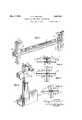
If horizontal muntins, such as indicated at 71 and 73, are called for, I arrange so that these can be put in lace by vertical movement as shown in Figs. 11 and 15. At the sides of the sash a cli 72 is welded in place in the glass-pocket o the side rails 10 but toward the outside of the window. The muntin bars 71 (see Fig. 11) have the two side plates 62 and 64 cut to butt against the folded inner edges of the side rails 10, while the web 66 extendsinto the glass-pocket where it is engaged by cli 72. The head 68 extends over to meet ead 16. At the point where the horizontal muntins meet the vertical ones, the side plates, web and bead of the horizontal pieces are cut to meet the corresponding parts of the vertical muntins.
To glaze a window such as shown in Fig. 1, the pole socket 34 is removed, permitting the removal of cover plate 30. Thethree lower lights of glass are then slipped down in place and set in putty. The two horizontal muntins 71 that are at the sides are then inserted diagonally with their webs 66 in the clip 72, and the portions adjacent the vertical muntins are pushed down into lace. The central horizontal muntin 73 can e put in place by direct-vertical movement. In order to hold the horizontal muntins in position at their points of intersection, I prefer to use a square plate 74 which is screwed on the outside of the vertical muntin bar. The corners of this plate are stamped in, as indicated at 76 to lock "the horizontal muntins against vertlcal movement. Instead of plate 74, I may use two removable pins 77 and 78 as shown in Fig. 15. These pins pass through the web 66 of the vertical muntin andhold the honzontal muntins against movement. After the horizontal muntins are in place, the three upper lights of glass are inserted and the cover late then returned to positlon.
In tlie lower sash the muntins are attached in a similar manner. At the meeting rall, the outer plate 62 of the vertical muntin bar is welded to the outside face of plate 52. At the bottom, clips similar to clip 72 are used and the head 68 is spot welded to the bottom rail 40 so that the appearance along the bottom rail is similar to that along the side rails.
It is understood that the foregoing examples are given only by way of illustration and may be modified in many particulars without departing from the spirit of my invention.
What I claim is:
1. A window-frame comprisin side and bottom members formed with g ass channels, a plate connecting the upper parts of such side members so that-a piece of glass may be slipped by such plate into said channels and a folded cover plate adapted to he slipped over said connecting plate to hold theupper edge of the glass, said cover comletely hiding said late upon the inside and adapted by siiape and size to be positioned upon the plate to complete the frame with the contour of the side members so that the cover is the visible portion of the inside of the top.
2. A structure as specified in claim 1, in which each side member is formed of a piece of sheet metal bent to form a sash plate and the glass channel.
3. A window comprising side members having glass channels, vertical muntins between the side members having glass channels, means for holding the ends of the glass channels and side members in spaced relation, while leaving one end of such channels open to receive glass, means for closing such end of said channels, horizontal muntin members adapted to be interlocked with the side members and vertical muntins by a movement in the plane of the vertical muntins and having a component along the line of such vertical muntins, and means for holdlng such horizontal muntins against vertical movement. p
4. A metal window frame formed with side members of sheet metal each bent back upon itself so as to form a fold and a glass rabbet, a bottom member having a glass rabbet, a cross plate permanently joining the top of said sides with ends extending lnto the said folds, and a removable cover for said cross plate formed of metal of substantially the same thickness as said side members and bent to form a glass rabbet adapted to rest upon said plate, said plate being adapted to unite the inside surfaces of said side members and said cover and hold them in substantially the same plane.
5. A metal window frame comprising side and bottom members permanently connected, a cross plate permanently connecting said side members, a vertical muntin bar formed with an inner and outer face plate and permanently connected with said bottom member and cross plate, and a removable folded cover for said cross plate folded so as to form a glass rabbet and adapted to be slipped over said cross plate, the inner face plate of said muntin bar being projected upwardly so as to hold a portion of the cover in position between itself and said cross plate, all of said permanently connected members being so positioned as to allow glass-to be inserted when the cover is removed.
6. A sheet metal window frame comprising side members of integral sheets each folded back upon itself to form a stiffening head on the inside portion and a glass channel, a connecting bottom member, a top connective plate entering the folds of the side members, and a removable folded cover for said top plate adapted to be slipped over and rest upon said top plate and shaped to form a glass channel for the top of the glass, said cover being formed with an inside portion substantially similar in cross section to the inside portion of said side members, said top connective plate being adapted to align the inside portions of the cover and the sides.
7. In a metal window sash, folded sheet metal sides formed with a glass channel, a bottom connective member provided with a glass channel, a connective plate uniting the top of said sides so formed as to allow glass to be slipped into the glass channels, and a removable cover for said plate adapted to hold glass in place and to fill out the structural form of the window, said plate being adapted to align the cover with the sides.
8. A structure as defined in claim 7, wherein the ends of the cover and the tops of the sides are mitred, and said plate is adapted to align the corresponding-mitred edges even- 9. A bottom window sash formed of sheet metal comprising sash members of integral sheet metal folded back upon themselves so as to form glass rabbets, a bottom member folded back upon itself to form a glass rabbet, said side and bottom members being permanently connected, a top member formed of a strip of sheet metal, the ends of which enter into the folds of said side members and a portion of which is bent outwardly and downwardly to form a meeting rail, said top member being adjacent but substantially out of the plane of said glass rabbets, a cover plate for said top member bent so as to form a glass rabbet with said top member, and means to removably position said cover plate upon said top member.
10. A top window sash formed of sheet metal comprising side members formed of a sheet of metal each bent back upon itself so as to form a glass rabbet, a bottom member joining said side members formed of an integral plate bent so that it is adapted to form a meeting rail and being connected to said side members, a member welded upon said bottom member adapted to form a glass rabbet with said bottom member, a top plate permanently connecting said side members and having ends extending into the folds of the latter. and an integral piece of folded sheet metal formed so that it may be slipped over said plate and so that it-and a part of said'plate form a glass rabbet and means to removably position said folded piece of sheet metal in place over said plate.
' HARRY E. CAMPBELL.
Priority Applications (1)
| Application Number | Priority Date | Filing Date | Title |
|---|---|---|---|
| US383189A US1857093A (en) | 1929-08-03 | 1929-08-03 | Window sash and muntin construction |
Applications Claiming Priority (1)
| Application Number | Priority Date | Filing Date | Title |
|---|---|---|---|
| US383189A US1857093A (en) | 1929-08-03 | 1929-08-03 | Window sash and muntin construction |
Publications (1)
| Publication Number | Publication Date |
|---|---|
| US1857093A true US1857093A (en) | 1932-05-03 |
Family
ID=23512088
Family Applications (1)
| Application Number | Title | Priority Date | Filing Date |
|---|---|---|---|
| US383189A Expired - Lifetime US1857093A (en) | 1929-08-03 | 1929-08-03 | Window sash and muntin construction |
Country Status (1)
| Country | Link |
|---|---|
| US (1) | US1857093A (en) |
Cited By (2)
| Publication number | Priority date | Publication date | Assignee | Title |
|---|---|---|---|---|
| US2473298A (en) * | 1946-02-14 | 1949-06-14 | Reconstruction Finance Corp | Window construction |
| US4747248A (en) * | 1987-05-14 | 1988-05-31 | Philips Industries Inc. | Corner construction for extruded frame components |
-
1929
- 1929-08-03 US US383189A patent/US1857093A/en not_active Expired - Lifetime
Cited By (2)
| Publication number | Priority date | Publication date | Assignee | Title |
|---|---|---|---|---|
| US2473298A (en) * | 1946-02-14 | 1949-06-14 | Reconstruction Finance Corp | Window construction |
| US4747248A (en) * | 1987-05-14 | 1988-05-31 | Philips Industries Inc. | Corner construction for extruded frame components |
Similar Documents
| Publication | Publication Date | Title |
|---|---|---|
| US3491584A (en) | Door with metal outer facing and/or frame assembly therefor | |
| US2155729A (en) | Miter joint | |
| US1940968A (en) | Paneling structure | |
| US1445738A (en) | Portable bungalow | |
| US1857093A (en) | Window sash and muntin construction | |
| US2114896A (en) | Window construction | |
| US891604A (en) | Joint for window and door screens. | |
| US2174180A (en) | Museum and display case | |
| US2874420A (en) | Metal door frame | |
| US2747705A (en) | Reversible metal doors | |
| US1150755A (en) | Metal door. | |
| US2137677A (en) | Wall assembly | |
| US1645692A (en) | of portland | |
| US2286493A (en) | Door construction | |
| US1897010A (en) | Window | |
| US2203987A (en) | Corner piece for frames | |
| US2561142A (en) | Sash construction | |
| US2607960A (en) | Wood core metal-sheathed door | |
| US1748103A (en) | Metal door | |
| US1712107A (en) | Sheet-metal door | |
| US2714431A (en) | Window frame structure | |
| US1076143A (en) | Show-case construction. | |
| US1111323A (en) | Window. | |
| US1138837A (en) | Metal door. | |
| US1741890A (en) | Auto screen |