US1857074A - Hood capping container - Google Patents
Hood capping container Download PDFInfo
- Publication number
- US1857074A US1857074A US58613A US5861325A US1857074A US 1857074 A US1857074 A US 1857074A US 58613 A US58613 A US 58613A US 5861325 A US5861325 A US 5861325A US 1857074 A US1857074 A US 1857074A
- Authority
- US
- United States
- Prior art keywords
- cap
- bottle
- caps
- container
- hood
- Prior art date
- Legal status (The legal status is an assumption and is not a legal conclusion. Google has not performed a legal analysis and makes no representation as to the accuracy of the status listed.)
- Expired - Lifetime
Links
- 238000010438 heat treatment Methods 0.000 description 39
- 239000011230 binding agent Substances 0.000 description 20
- 239000000463 material Substances 0.000 description 18
- 238000000465 moulding Methods 0.000 description 10
- 230000007246 mechanism Effects 0.000 description 9
- 230000003028 elevating effect Effects 0.000 description 7
- 238000000034 method Methods 0.000 description 7
- 238000009877 rendering Methods 0.000 description 6
- 241000282472 Canis lupus familiaris Species 0.000 description 5
- 230000005484 gravity Effects 0.000 description 5
- 241001527902 Aratus Species 0.000 description 3
- 238000003825 pressing Methods 0.000 description 3
- 101100379079 Emericella variicolor andA gene Proteins 0.000 description 2
- 238000010276 construction Methods 0.000 description 2
- 230000008602 contraction Effects 0.000 description 2
- 230000000994 depressogenic effect Effects 0.000 description 2
- 239000002184 metal Substances 0.000 description 2
- 239000008267 milk Substances 0.000 description 2
- 210000004080 milk Anatomy 0.000 description 2
- 235000013336 milk Nutrition 0.000 description 2
- 238000000926 separation method Methods 0.000 description 2
- 241000736839 Chara Species 0.000 description 1
- 230000001174 ascending effect Effects 0.000 description 1
- 230000015572 biosynthetic process Effects 0.000 description 1
- 238000001816 cooling Methods 0.000 description 1
- 238000003780 insertion Methods 0.000 description 1
- 230000037431 insertion Effects 0.000 description 1
- 238000007689 inspection Methods 0.000 description 1
- 238000002844 melting Methods 0.000 description 1
- 230000008018 melting Effects 0.000 description 1
- 239000000203 mixture Substances 0.000 description 1
- 238000012986 modification Methods 0.000 description 1
- 230000004048 modification Effects 0.000 description 1
- 230000010355 oscillation Effects 0.000 description 1
- 238000012856 packing Methods 0.000 description 1
- 244000144985 peep Species 0.000 description 1
- 230000000452 restraining effect Effects 0.000 description 1
- 239000011435 rock Substances 0.000 description 1
- 230000001954 sterilising effect Effects 0.000 description 1
- 239000000126 substance Substances 0.000 description 1
- 238000012546 transfer Methods 0.000 description 1
Images


Classifications
-
- B—PERFORMING OPERATIONS; TRANSPORTING
- B67—OPENING, CLOSING OR CLEANING BOTTLES, JARS OR SIMILAR CONTAINERS; LIQUID HANDLING
- B67B—APPLYING CLOSURE MEMBERS TO BOTTLES JARS, OR SIMILAR CONTAINERS; OPENING CLOSED CONTAINERS
- B67B3/00—Closing bottles, jars or similar containers by applying caps
- B67B3/02—Closing bottles, jars or similar containers by applying caps by applying flanged caps, e.g. crown caps, and securing by deformation of flanges
- B67B3/026—Closing bottles, jars or similar containers by applying caps by applying flanged caps, e.g. crown caps, and securing by deformation of flanges the caps being made of thermoplastic material
-
- B—PERFORMING OPERATIONS; TRANSPORTING
- B67—OPENING, CLOSING OR CLEANING BOTTLES, JARS OR SIMILAR CONTAINERS; LIQUID HANDLING
- B67B—APPLYING CLOSURE MEMBERS TO BOTTLES JARS, OR SIMILAR CONTAINERS; OPENING CLOSED CONTAINERS
- B67B5/00—Applying protective or decorative covers to closures; Devices for securing bottle closures with wire
Definitions
- This invention relates to treating plastic hood caps to render them temporarily moldable and applying such caps to containers; and the objects and nature of the invention will be readily understood by those skilled in the art in the light of the following explanations of the steps followed, and of the accompanying drawings that illustrate what we now believe to be the preferred mechanical expression or embodiment of our invention from'among other forms, constructions and arrangements within the spirit and scope of our invention.
- the invention consists in certain novel steps, and features, and in combinations or arrangements, as more fully and particularly set forth and specified hereinafter.
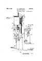
- Fig 1 is an end elevation of hood cap softening, applying and securing apparatus of our invention, the hood cap heater and applicator being shown in side elevation.
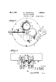
- Fig. 2 is a detail top plan of the hood cap heater, dotted lines showing certain hidden features and also indicating the limit of anticlockwise movement of the reel operating lever.
- Fig. 3 is a detail front elevation of a portion of the means at the lower end of the heater for gripping the hood cap and holding the same on the container mouth during the Iwithdrawal of the containerfrom the heater. ⁇ y
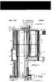
- Fig. 4 is a detail vertical longitudinal section of the hood cap heater and cap gripping devices.
- Fig. 5 is a detail cross section on the line 5-5, Fig. 4.
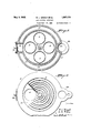
- Fig. 6 is a detail top plan of the heater withgthe reel and heater top plate removed.
- Fig. 7 is a detail bottom plan of the heater nozzle or mouth and the cap gripping devices.
- Fig. 8 is a detail view showing thezlower portion of the heater nozzle in vertical. sec'- tion, and several of the nested moldable hood caps therein in vertical section, the cap gripping devices being shown in elevation in their normal inoperative positions, the head or mouth portion of a bottle being shown, in elevation, on its upward movement to enter the bottom cap in the nozzle.
- Fig. 9 is a detail view similar to Fig. 8 with the exception that the bottle is shown in position on its upward movement about to enter the lower cap, and the cap gripping de ⁇ vices are shown in the positions on their ⁇ upward movements where they are about to swing up and out to grip the lower cap after the bottle mouth or head has seated itself within suchcap.
- Fig. 10 is a detail view similar to Fi ⁇ gs. 8 and 9, with the exception that the bottle head is shown seated in the bottom hood cap and about to start on its withdrawal movement with s aid cap and the gripping devices are shown in position gripping and holding the vcap tovmove down with the'bottle.
- Fig. 11 is a bottom plan view of the cap heater nozzle provided with a modified construction of cap gripping devices.
- Fig. 12 sectional elevation of the heater nozzle and gripping devices of Fig. 11, a bottle mouth being shown in elevation moving up to enter the bottom cap in the nozzle, the gripping devices being shown in their normal inoperative positions.
- Fig. 13- is a' view similar to Fig. 12 but showing the bottle head in the lower cap in the nozzle and the gripping devices in operative cap gripping positions; the bottle, cap
- caps are thus rendered self-securing by the presence of a binder on or in (or both) the cap skirts, at least the securing portions of i magazine or feed bore is open at its lower end A such skirts, that has the quality of rendering the portion of the skirt that embodies the binder hard or stiff at climatic temperatures, and soft or moldable when more or less highly heated, say, to the temperature of or approaching the melting point of the binder which usually runs between two and three hundred degrees Fahrenheit more or less.
- Each cap is preheated so that its skirt is soft and moldable, and is applied to the container to be capped thereby while in this moldable condition.
- the hotv moldable skirt of the cap properly positioned on the container mouth, is then molded to the container neck or radially and annularly compressed to lit under the exterior rim of the container mouth and thus held until 'the skirts set to rigid stiff form and secured position and condition.
- caps in this magazine are subjected to the required high temperature for the necessary length of time to render the securing portlons of the cap skirts soft and moldable, and also cap separating and applying means whereby the hot caps are individually discharged or removed rom the magazine and placed on the containers in position and condition to be secured as hereinbefore described.
- hood cap heating and dispensing vessel or container 2 that provides a vertical depending cap magazine and discharge or dispensing -nozzle 3, forming an internal vertically elongated usually cylindrical feed bore or receptacle 4 for a column or un'it of nested hood caps 1.
- the inner surface of this bore is usually smooth to permit free downward movement of the caps by gravity, and its internal diameter is such with respect to the maximum diameter of the caps as to guide the same in their vertical movement. This for successive downward vertical removal of the bottom end caps of the'graduall 1 descending column of caps in the bore.
- T e column of caps is upheld in the bore by any suitable means although for this purpose we happen to show several vertical spaced light flexible spring fingers 5, having their depending lower ends free and inclined inwardly and downwardly into the bore atthe lower end thereof so that. the lower edge of the bottom cap ⁇ of the column1 of caps will engage the free ends of the springs and normally uphold the column, until suflicient downward force is exerted on the lower cap to force the springs radially outward to permit passage of such cap past the springs which will return to normal position and engage the next cap above to prevent continued downward passage of the remaining caps from the bore.
- detent or supporting fingers 5 are usually arranged in vertical slots extending radially through the magazine wall and are carried by angle or L-shape brackets 6, adjustable radially of the bore, through the medium of slots in the horizontal ends of the brackets fitting the bottom end face of the magazine, and securing or clamping screws 6a, extendin through said slots into the bottom edge o the magazine.
- the upper portion of the cap heating container is enlarged above the depending nozzleto provide an internal closed vertical heating ⁇ chamber 10 of en: larged diameter for the reception of avertical horizontally rotatable reel 7, rotatable on fixed vertical axis 8, eccentrically arranged with respect to the longitudinal axis of bore 4.
- This reel 7 provides a plurality of similar vertically elongated cap unit bores, passages or tubes 9 open at their upper and lower ends.
- the reel is constructed and arranged to be rotated step by step and to bring the lower ends of these tubes 9 successively into registration'with the upper end of the bore 4, so that the charges of caps in said tubes can be successively discharged or dropped into bore 4, to maintain a supply.
- Each tube 9, is of sulicient length to receive a unit or column of nested hood caps, arranged with their skirts depending (say, about one hundred hood caps to a unit, more or less) and the magazine bore 4is also of suilcient length to receive such unit of caps.
- the internal diameter of the tubes 9, is approximately the same as the internal diameter of bore 4, so that the cap units of nested caps can freely slide down therein by gravity.
- the cap heater and magazine 2 is vertically.
- the internal heating chamber 10 is closed at th'e bottom by a at iioor 11, designed to support the columns of caps in the tubes 9 of the reel 7.
- the upper end of the magazine bore 4 opens through this floor 11, so that when a tube'9 of the reel 7 registers with magazine bore 4, the caps in'said tube 9 will drop by gravity into bore 4 onto the fuppermost cap of those remaining in said bore or onto the fingers 5, if said bore coni tains no caps.
- the caps in the tubes 9 of the reel 7, that are not in registration with bore 4 are upheld by floor 11 and the bottom caps in saidV tubes slide on said floor as the reel advances toward the bore 4.
- the reel consists of top and bottom disk-like heads carrying the uniformly spaced vertical tubes 9 that open through the heads; the heads being formed step to carry the tubes 9thereof in succession in an endless path to a filling station where each tube receives a unit of cold caps,'and then through the heating chamber, and then to the discharge station, namely into registration with bore 4, and then back to the filling station.
- the reel is rotated to advance the tubes 9 clockwise, and we happen to show the reel provided with four tubes 9, and hence locate'the tube filling station one step behind the tube discharge station so that the iilled tubes will remain in the heating chamber for a maximum length of time to insure that the caps kare softened and moldable before being dropped into bore-4 at the discharge station.
- the filling station can be formed by a vertical port 14, through the top plate 12, of sufficient size to permit free downward passage of a unit of caps into a tube 9, registering with'and located under said port, said port being arranged so that the tubes 9 pass in succession into-registration therewith.
- a tube 15 can be erected on the top plate 12, alined with the cap supply port, and this tube can contain one or more units of nested caps to feed or drop'by gravity through port 14 and into the reel tube 9 registering with said port.
- the caps in supply tube 15 are normally upheld therein by a horizontal cover plate 16, that normally covers the port 14, and forms the bottom floor of the tube 15.
- This cover plate 16 is horizontal and arranged on the upper face of the top plate 12, and is laterally movable to and from operative position over the port 14 and within the tube 15, to permit a unit of nested caps to dro into a tube 9 for heating.
- this cover plate 16 is carried by and forms the projecting free end of an exposed accessible horizontally swingable lever 17, having a hub 18 mounted and rotatable on the projecting upper end of the top hub 13 of the reel 7.
- This lever is located above the cap heating container and projects forwardly and is swingable laterally and is arranged to cooperate with certain features to advance the reel 7 forwardly step by step to carry the tubes 9 forwardly at each step the distance from the discharge station to the loading station.
- the lateral swing of the lever 17 is limited by adjustable stops 19 to attain the desired moreor less accurate registration of the tubes 9 with the cap port v 14 and thc magazine bore 4.
- Suitable means are provided to operatively lock the hand lever 17 to and release the same from the reel 7 for advancing the reel a step and for the free return swing of the lever.
- the reel hub 13 formed with radial sockets 20, and the lever hub provided with a radially slidable retractive pin 2l, adapted to enterl any one of said sockets to operatively connect the lever and reel.
- a spring 22 can be provided .to pr'oject the pin and a hand clip and pull connection 23 to withdraw the pin.
- the normal position of the lever is at its limit of swing toward the right, i. e. anticlockwise, with its plate 16 covering the cap port 14 and forming the floor of tube 15 and supporting a unit of cold caps in said tube.
- all of the tubes 9 of the reel should be filled with caps undergoing heat treatment for softening to moldable condition.
- the reel should be advanced a step.
- Means are -provided whereby the operator is informed when the magazine bore 4 needs
- a peep or inspection window 25 through the front wall of the cap heating container into the upper portion of bore 4 and the lower portion of heating chamber 10.
- This window is closed against substantial loss of heat by transparent panel 26.
- the outer side 'of the lower portion of the wall of each tube 9, is longitudinally slotted, so that the operator throu h the window can observe the presence or a sence of caps in the tube 9 at discharge station, and hence determine when the supply of tubes in bore fl, needs replenishing.
- any suitable source of heat can be utilized to maintain the desired cap. softening temperature within the cap heating container, and such container can be of any suitable formation and variously equipped as may be required by the particular heating medium or heat source employed.
- steam is commonly employed for various purposes in the treatment of milk and in milk bottling establishments, we. have in the example illustrated, provided a metal cap heating container constructed to receive steam as the heating lnedium to maintain a cap heating temperature, say of about 220 F.
- a metal cap heating container constructed to receive steam as the heating lnedium to maintain a cap heating temperature, say of about 220 F.
- the cap heating container is usually mounted'or supported in an elevated position so that the bottles to be capped can be located below and alined with the nozzle and elevated into the lower end thereof to receive a cap
- we preferably form said container with exterior supporting means For instance, we show the rear of the container formed with an exterior' longitudinal groove 28 and rearwardly projecting horizontal loops 29, to receive a fixed vertical rear supporting post 230, on which the container is vertically adjustable. Suitable means are provided for vertically adjusting the container and holding the same at the desired elevation. For instance, we show a step block 3l securedto and projecting laterally from the post 30, and a vertical adjusting screw 32 at its lower end seated in said block and at its upper endV havlng a. handle.
- the upper loop 29 of the cap container is formed with a vertical tapped bore 33 -through which the screw passes and that forms a nut on the screw that is moved vertically by rotation ofthe screw.
- the screw By rotation of the screw the cap treating and dispensing container can be bodily elevated and depressed to the desired vertical position and thus held.
- the container slides vertically on the post and is preferably normally confined thereto against horizontal swing or oscillation thereon.
- the bottle or other container b to e exteriorly capped by a cap from the heating and dispensing container 2, is located below and longitudinally alined with the longitudinal axis of the nozzle', and on relative vertical movement between the container 2 and the bottle, the bottle mouth and the bottom cap in said nozzle are brought together.
- the bottle is inserted by hand or otherwise into the lower end of the bore 4 of the nozzle, or the container is moved down to the bottle, the relative movement is preferably such that the bottle mouth enters the bottom downwardly flaring softened hood cap upheld by the fingers 5 and the cap is centered on the bottle top with its flat top engaging the top edge of the bottle mouth.
- the bottle and nozzle must then be vertically separated to clear the bottle from the nozzle, and the cap must remain properly seated on the bottle mouth and hence be separated from the caps remaining in the nozzle and from the fingers 5.
- the cap heating and dispensing container supported in elevated normally fixed position withthe elevated nozzle overhanging a.
- horizontal longitudinally elongated bottle support,' such as a table 35 on which the bases of the bottles rest and along which a row or one or more bottles can slide or otherwise advance so that the ⁇ bottles can pass forward under the nozzle connection' 38 at its lower end secured to and extending upwardly from the treadle, and laterally over idler pulleys 38a, and downwardly to the lower portion of depending slide 37, to which said cable is secured, whereby the holder can be elevated and thus held by depression of the treadle.
- the structure and arrangement is preferably such that the bottle support and its slide will drop to normal depressed position on release of the treadle.
- the support is thereby elevated carrying the bottle up and projecting the bottle mouth into the bottom cap in the nozzle, as hereinbefore explained.
- the fingers are controlled and operated by a vertically movable slide 42 and toggles and stop
- the slide 42 is in the form of an exterior sleeve slidable longitudinally on the nozzle 3 and normally located at its limit of downward movement with the fingers in retracted or inoperative position.
- This sleeve 42 is limited in its downward movement on the nozzle 3 by a suitable stop, and its vertical operative movements are controlled, in the example illustrated, by the vertical movements of the stem or slide rod 37 of the bottle elevating support through the medium of a stop 37a, normally fixed to but vertically adjustable on rod 37, arranged to engage and lift an arm 44 normally fixed to and projecting laterally from a vertical slide rod 43 at its upper end coupled to sleeve 42, as by a fork 45 and pivot pins or trunnions 46.
- the range of vertical movement of the stem 37 of the bottle elevating support is yusually longer than that of the sleeve 42 which sleeve rises and lowers with the bottle support while that support is moving through the upper portion of its up and down strokes.
- the brackets cal ry a pair of toggles, respectively', each embodying a cap grasping or holding finger 40.
- Each toggle consists of an outer link or lever member 48, at its outer end mounted on relatively fixed transverse axis 48a and an inner link or lever 40a, the inwardly projecting inner end or extension of which forms one of the fingers 40.
- the outer end of lever 40a is pivotally joined to the inner end of link 48, by transverse pivot pin 49.
- the lever 40a intermediate its ends is fulcrumed to rock on transverse pin 50, and this pin 50 is slidable inthe bracket radially of the sleeve 42 and the nozzle 3,
- a coiled spring 51 constantly exerts its tension on pin 5() to hold the same to its limit of outward movement and to return the same to such limit and hence to hold the toggle in broken position with the pin 49 out of alinement with the pins 48a, 50.l
- each toggle lever curves downwardly, inwardly and upwardly, in the particular example shown, to form the nger 40 of U shape or hook form, or to extend down and inwardly past the'lower end of the nozzle and to provide an upstanding free end to project up in thenozzle and within the depending skirt of the cap on the bottle mouth, said upstanding end having the outwardly directed prick or pin point 41, which on outward swin of the finger will prick or grasp the cap s irt from the inside thereof.
- the center or knuckle pivot pins 49 of the finger controlling toggles project laterally from the tog'- ⁇ gles and these projecting pin ends move vertically (as sleeve 42 slides up and down) between upper and lower normally fixed stops 53 carried by fixed brackets 54 secured to and depending from the nozzle 3.
- An upper and a lower stop 53 is provlded for each toggle and its projecting ⁇ joint or knuckle pin 49, and provision is made for independent vertical adjustment of each stop 53 on lts bracket 54.
- the gripping fingers thus maintain their hold on the cap that is seated on the descending bottle mouth, until the descending cap is entirely detached from and free of the caps left in bore 4 and the nozzle 3, and fingers 5, and thereupon, the projecting toggle pins 49 are stopped in their downward movement by engagement with the lower stops, which on continued downward movement of sleeve 42, break the toggles upwardly causing withdrawal of the gripping fingers from the cap on the bot- Ytle by downward and outward swing of said lingers to positions clear of the cap and bottle and out of the path followed by the bottle in moving along the table for reception of means to contract and clamp the moldable Aflaring skirt of the cap tosecured position under the exterior rim of the bottle.
- Vertically adjustable stop screws are, preferably, provided, to accurately limit and set the downward breaking movement of the toggle and the consequent outward radial throw of the pricking points of the gripping fingers when taking hold of the cap skirts.
- Various other means can be provided to operate the gripping fingers to causethem to take hold of and release the caps.
- a rack and pinion actuating means can be utilized instead of the toggle device.
- stationary racks 56 depend from the nozzle 3, and the brackets 57, fixed to and carried by the sliding sleeve 42 and depending therefrom, carry transverse horizontal shafts or spindles 58, on which are mounted pinions in mesh with the racks 56.
- the cap gripping oi picker fingers 59 are approximately U or hook shaped with sharp pointed free ends to function as described in connection with fingers 40. Each finger 59 is swingable on its spindle 58 as an axis, and in this instance is formed with a transverse hub rotatable freely on its spindle 58 except as controlled by the pinion 60 on suchv spindle.
- Each toothed finger 59 is provided with a coiled reti-active spring 62 acting thereon to swing t-he finger upwardly, inwardly and outwardly to cap gripping position, and stops and trip devices are provided whereby the fingers after gripping the cap will remain in such gripping position on the downward movements of the bottle, cap andhsleeve 42, until the cap is clear of the nozzle 3 and the caps therein, whereupon the rotation of the pinions by engagementw-ith the fixed racks will cause downward and outward swing of the fingers to positions free of and removed from. the cap on the lowered bottle.
- the coiled contractile spring 62 of a gripping finger actuating device is secured at its inner end to said finger and 4at its outer end is secured to the adjacent end of the geared pinion 60, and the pinion is provided at one end with al projecting finger-depressing pin 68.
- the hub of the finger is formed with a shouldered depression or tooth 65, to receive the locking end of spring dog or' detent 66.
- a hood cap having a hot flaring moldable skirt as received ,from the cap softening and dispensing container, is han- V dled or ⁇ conveyed in any suitable manner or by any suitable means, to hood cap skirt con- ⁇ tracting and molding means or mechanism for contracting ,and molding the hot soft rap skirt to the bottle neck under the eX- terior rim of the bottle and for thus holding the skirt until it sets and hardens'to tight contracted securing condition on the bottle neck and rim, whereu on the securely exteriorly capped bottle 1s ready for packing, shipment or delivery.
- Each bottle might be taken by hand from' the cap receiving station, and radially and annularly contracting means might be exteriorly applied to the hot moldable skirt of the hood cap on the bottle, by hand or otherwise, to contract theskiijt and hold the saine until setto stiff permanent secured position, whereupon such means might be removed.
- Various molding and contracting means'might be employed for this purpose, and we have not herein illustrated such means in detail, as our instant invention involves means for rendering the hood cap skirts moldable and dispensing such caps while their skirts are moldable onto container mouths.
- each bottle head as a form or mandrel on which to mold a hood cap from a flat disk.
- Means for 'softening hood cap skirts i paper hood caps and to feed the same to said A discharge with the caps in upright position having their skirts depending, provision being made to lmaintain a cap binder softening temperature in said passage.
- Means for rendering paper hood caps moldable and for delivering such moldable caps onto bottle mouths for ultimate molding thereon embodying a hood cap heating vcontainer providing a feed -magazine for a stack of nested binder carrying paper hood caps leading to a discharge station, said container having means at said station to maintain a'hot hood cap ⁇ with its moldable skirt depending in' position to receive a bottle mouth, and meansto hold the cap on the bottle to withdraw from the station with the bottle and positioned on the bottle mouth.
- bottle elevating vand withdrawing means an elevated hood cap heating and dispensing containerhaving aA vertical mouth to receive the bottle mouth, said container providing a feed magazine for a stack of binder carrying4 paper hood caps to feed'them successively to lsaid mouth and provided with means to receive and uphold a heated softened cap at said mouth to lit on a bottle mouth moved upward therein, and movable hood cap gripping means operatively connected with said elevating means to grip the cap at said mouth and entered by the elevating bottle and to withdraw said cap from the mouthand on the bottle mouth and with the bottle.
- a hood cap heating and dispensing container having a hood cap discharge mouth and a magazine bore leading Jup. from said mouth to guide and feed down a stack of hood caps; said container having means to supportv the caps in said bore for successive with;
- those steps which comprise, maintaining a multiplicity of binder-carrying paper material hood caps under binder softening temperature to provide a supply of hood caps in moldable condition and advancing the same toward a dispensing-station; successively rcmoving caps in temporary moldable condition at said station from said advancing supply and dispensing the same -to containers for ⁇ molding and holding thereonl until set to securing condition; and preheating a multiplicity of binder carrying hood caps and replenishing said supply therewith and subjecting said preheated caps to said softening temperature.
- a Ahood cap heating and dispensing container having a discharge mouth and provided with means for maintaining hood cap binder softening temperatures Within the container, a reel invsaid container having a series of passages to carry charges of hood caps subjected to said softenin temperatures' for heating and successive elivery for feeding to said mouth, means for advancing said .reel step by step, a hood cap supply with which said passages are 4successively brought in cooperative relation to receive charges ofl caps, and means for closing ⁇ and ,openin said supply.
- a'feed magazine for al multiplicity of paper material closure disks carrying blnder and arranged in stack form
- said magazine havin a closure disk discharge and setting'on containers; means for advancing stacks/ofsaidfdisks for delivery to said4 magazine; means being provided for pre-- heating said advancing stacks of disks for delivery tol said magazine, and to heat the 'diskfin the' magazine to maintain therein a supply, of disks in a temporarily moldable condition.
- Container closure applying apparatus comprising a lder for a multiplicity 4,of paper material closure .disks havingbinder carrying annular 'flaring skirts; heating means to-raise said disks to a skirt softening temperature for molding and thus maintain a supply of such disks in a moldable condition; and dispensing mechanism for quick successive delivery of hot moldable disks from said supply of disks direct to containers in' condition for molding and setting thereon.
- Mechanism for applying pa er material binder carrying hood -cap dis while temporarily in a moldable condition to container heads for pressing and holding thereon until set to secured condition comprising a disk holder embodyin a vertical feed magazine for a stack o binder-carrying paper material hood cap disks, having a top supply' opening for entrance of stacks of such disks and a bottom discharge elevated above a support for containersto be closed by such disks; heating means for heating a supply of disks in said magazine to render them moldable and for maintaining the disks at said dischar e in moldable condition; means for upholding the-disks in the magazine with the bottom moldable disk atsaid discharge; means for moving the container support to bring the container head a ainst the moldable disk atlsaid discharge angl verf tically movable means for dispensing mold- J able disks from said discharge with the container heads.
- an elevated feed magazine for a' stack of nested paper material hood caps having a bottom discharge mouth and means to uphold the caps in themagazine with the bottom cap in container head-'receivin position; a container support arrange to su port the container to be capped with its hea opposite and alined with said mouth; means to bringxtogether the container and saidnitouth with t e container head Within said botom cap and to then separate the container and ma a'zine; and vertically.
- an upright feed magazine for a stack of nested paper material flaring skirt hood caps said magazine having and feeding the caps down to a ,discharge mouth, means to uphold the bottom cap at said mouth; a vertically movable container support arranged to supporta container with its h ead below and approximate- 1y alined with said mouth to receive a hood cap direct therefrom; and avertically movable cap transfer devicel for successively pulling the caps from the stack and' carrying the same one at a time down from said mouth with the cap finally centered on the container for securing.
- a eed magazine havhead with its skirt depending in positionv ing an open end, said magazine formed to t feed a stack of paper material hood caps toward said end and there maintain the end cap in posi-tion to receive the head of a container to be capped thereby, means to carry the container to be capped toward and from Y the magazine 4 to enter its head into the end vcap and to withdraw the container with the capl on its head; and reciprocatory cap disipensing mechanism having lingers to grasp said end cap by its flexible skirt and strip the cap from the magazine and hold the cap on the container head as it withdraws from the magazine.
- apparatus for hood capping containers in combination, means for maintaining a supply of paper material binder carrying hood capping disks in a moldable condition for quick individual separation and dispensing on container heads for moldingand setting thereon, embodying a feed magazine for a stack of a multiplicity of such disks, means for heating the disks of such stack to approximately fuse the binder and render the disks moldable and for maintaining the disks in such condition for dispensing moldable disks from such supply; and movable means for successively separating ⁇ and removing the moldable disks from the magazine, said means embodying resiliently actuated moldable d k grasping means.
- a hood ap heating and dispensin container providing a discharge mouth an embodying means to maintain heat within said'cont'ainer to render the hood ca s'there.- inmoldable; means to hold a molda le hood cap atsaid mouth with its 'skirt depending to receive the head of the bottle tofbe capped; said container providing an' internal heated ⁇ magazine adapted to receive.
- hood caps for applying hood caps to container heads, comprisin a magazine havingl a discharge mouth, sai magazine adapted to receive a stack of a multiplicity of paper material flaring skirt nested hood caps and feed the same tosaid mouth, means b eing 'provided to u hold the caps with the bottom cap at sai mouth, means to'support the conta-incr to be capped approximately alined with said mouth' and relatively movable mechanism for dlspensing each hood cap from said mouth and leaving the same in capping position for securing on the head of the bottle on said support, said mechanism embodying cap gripping fingers operative to grasp a cap at said mouth by opposite portions of the cap skirt above its free edge and strip the cap
- hood cap disks having a bottom discharge
- said disks in the magazine advance by gravity to said discharge as disks are sucoessively removed therefrom; means being provided to render the disks in said magazine soft and moldable b heat to maintain a supply of such disks -1n a soft moldable condition for rapid successive removal -at 4o said discharge in a temporarily moldable condition; means for presenting successive bottles vertically a'lined with said magazine having their heads below and I centered aga-inst the bottom disks to receive successive temporarily moldable disks from said dischar e; and mechanism for forcibly dispensing te soft disks one at a time directly' down rom said discharge centered on and for removal with the bottle heads for contraction 50 and setting thereon.
- aratus for hood capping bottles embodyi g a vertically ⁇ movable support for the bottle to be hoodcapped; a supporting frame; a container carried by andA normally .'15 held at a fixed elevation by said frame with respect to saidsuppo'rt; means whereby said container can be set at various .elevations with respect to said frame and support; said container embo ying a discharge forhood M cap disks ina temporarily soft moldable con dition for application to the heads of successive bottles presented by said support, said container also providing a assageway for a plud' s advancing in suc- 05. cession: to said "harge, and means foi- ,f
- a support for the bottle to be hood capped a container' said container embodying a discharge for ood cap disks in a temporarily soft moldable condition for application to the heads of successive bottles presented vby said support, said container also providing a passageway fora plurality of hood cap disks advancing in succession to said discharge, and means for renderin said plurality of advancing disks soft an moldable for maintaining in said passageway a lurality of temporarily soft moldable dis s for quick successive removal from said discharge; and soft hood cap disk dispensing means for successively delivering such disks from said discharge.
- Apparatus for hood capping bottles embodying a bottle support; a ,container arranged above said support and providing/a hood cap disk dischar e above said supportand a passageway lead for a plurallty of advancing hood cap disks chara terized by the capacity of becoming ing to said discharge temporarily soft ⁇ and moldable when heated and of cooling toa hard set condition; said container providing means formaintaining said pluralit of disks in said passageway in a soft molda le condition and for successive ly presenting soft moldable disks at said discharge for centering and delivering on successive bottle heads for molding and setting thereon.; a vertically reciprocatory carrier, relatively movable fingers bodily carried verticall by said carrier toward and from said mout or successively removing .moldable disks therefrom, andA associated means for causing said relative movement Iof said fingers to take hold of and release said disks.
- supportingl means to carry a flexible skirtcd ho'od cap with its annular skirt depending to receive the head of the bottle to be capped, and movable means provided with fingers to entes the cap tle head in t ecap and hold the cap to the botskirt at theexteror of the bot- Ll tle head 'during the separation of the bottle and said supporting means, actuating and c ontrollin mechanism being prpvided for said mova le means and fingers to cause the 'same to grasp and release said caps, said supportin means and the bottles being relatively movab e to cause the bottle head to enter and separate from said supportingmeans.
Landscapes
- Engineering & Computer Science (AREA)
- Mechanical Engineering (AREA)
- Closures For Containers (AREA)
Description
May 3, 1932.A WL. www En.. 1,857,014
HO0D CAPPING CONTAINER P ileq sept. 25', 1925 1o sheets-sheet 2 gwvento JJ l @N MM i www,
W. L. WRIGHT ETAL HOOD CAPPING /QONTAI-NER Filed Sept. 25. 1925 May' 3, 1932.
10 Sheets-Sheet 3 May 3, 1932. w. L. WRIGHT Erm.
HOOD CAPPING CONTAINER Filed. Sept. 25, 1925 10 Sheets-Sheet 4 May 3, 1932. w. L WRIGHT E-Al. Hoon CAPPINQ con'rIuER Filed sept. A5, 192,5
io sneetslsneet 5 May 3, 1932. w. L, wanen-nf :TAL 1,857,074
-HOOD CAPPING' CONTAINER Filed Sept. 25, 1925 10 Sheets-Sheet 6 May 3, 1932. w. L WRIGHT nu. y 1,857,074
' noon cArPInG conulnkn.
rund swt. 25, 1925 1o sheets-sheet '7- May 3, 1932. w. l. WRIGHT ETAL HOQD GAPPING CONTAINER filed sept. 25, i925 10 SheertsPShet 8 May 3, 1932. w. 1.,.wmcH1'E-'rAL 1,857,074
HOOD CAPPING CONTAINER Filed sept. 25, 1925 1o sheets-sheet 9 w. L. WRIGHT E'rAL Hoon CAPPING CONTAINER 10 Sheets-Sheet 10 Filed Sept'. 25, 1925 314mm dois* WILBUR-L. WRIGHT AND LEE D. PIERCE, OF FULTON, NEW YO-RiK, ASSIGrINOIBS '.IIO`
lil
Patented May 3, 1932 v,UNITI-:1J STATES PATENT OFFICE OSWEGO FALLS CORPORATION, OF FULTON, NEW YORK, A CORPORATION OF NEW 'Yonx l Hoon caprine CONTAINER Application led September 25, 1925. Serial No. 58,618.
This invention relates to treating plastic hood caps to render them temporarily moldable and applying such caps to containers; and the objects and nature of the invention will be readily understood by those skilled in the art in the light of the following explanations of the steps followed, and of the accompanying drawings that illustrate what we now believe to be the preferred mechanical expression or embodiment of our invention from'among other forms, constructions and arrangements within the spirit and scope of our invention.
It is an object of this invention to provide for heating'and sterilizing paper or other flexible material hood caps, at least the annular securing portions of which embody a binder substance or composition rendering said securing portions stiff and hard at climatic temperatures and soft and moldable when more or less highly heated andto assemble and maintain a supply of temporarily moldable plastic caps, and to apply such caps when in the -moldable condition to container mouths for contraction of thel moldable skirt securing portions under the container rims and securing by the setting or hardening of such'portions in such contracted condition.
With this and other objects in view, the invention consists in certain novel steps, and features, and in combinations or arrangements, as more fully and particularly set forth and specified hereinafter.
Referring to" the accompanying drawings,- forming part hereof:
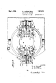
Fig 1 is an end elevation of hood cap softening, applying and securing apparatus of our invention, the hood cap heater and applicator being shown in side elevation.
Fig. 2 is a detail top plan of the hood cap heater, dotted lines showing certain hidden features and also indicating the limit of anticlockwise movement of the reel operating lever.
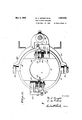
Fig. 3 is a detail front elevation of a portion of the means at the lower end of the heater for gripping the hood cap and holding the same on the container mouth during the Iwithdrawal of the containerfrom the heater.` y
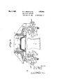
Fig. 4 is a detail vertical longitudinal section of the hood cap heater and cap gripping devices.
Fig. 5 is a detail cross section on the line 5-5, Fig. 4.
Fig. 6 is a detail top plan of the heater withgthe reel and heater top plate removed.
Fig. 7 is a detail bottom plan of the heater nozzle or mouth and the cap gripping devices. p
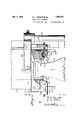
Fig. 8 is a detail view showing thezlower portion of the heater nozzle in vertical. sec'- tion, and several of the nested moldable hood caps therein in vertical section, the cap gripping devices being shown in elevation in their normal inoperative positions, the head or mouth portion of a bottle being shown, in elevation, on its upward movement to enter the bottom cap in the nozzle.
Fig. 9 is a detail view similar to Fig. 8 with the exception that the bottle is shown in position on its upward movement about to enter the lower cap, and the cap gripping de\ vices are shown in the positions on their` upward movements where they are about to swing up and out to grip the lower cap after the bottle mouth or head has seated itself within suchcap.
Fig. 10 is a detail view similar to Fi`gs. 8 and 9, with the exception that the bottle head is shown seated in the bottom hood cap and about to start on its withdrawal movement with s aid cap and the gripping devices are shown in position gripping and holding the vcap tovmove down with the'bottle.
Fig. 11 is a bottom plan view of the cap heater nozzle provided with a modified construction of cap gripping devices.
Fig. 12 sectional elevation of the heater nozzle and gripping devices of Fig. 11, a bottle mouth being shown in elevation moving up to enter the bottom cap in the nozzle, the gripping devices being shown in their normal inoperative positions.
Fig. 13- is a' view similar to Fig. 12 but showing the bottle head in the lower cap in the nozzle and the gripping devices in operative cap gripping positions; the bottle, cap
.of the container mouths that are exteriorly covered by the caps applied thereto. These caps are thus rendered self-securing by the presence of a binder on or in (or both) the cap skirts, at least the securing portions of i magazine or feed bore is open at its lower end A such skirts, that has the quality of rendering the portion of the skirt that embodies the binder hard or stiff at climatic temperatures, and soft or moldable when more or less highly heated, say, to the temperature of or approaching the melting point of the binder which usually runs between two and three hundred degrees Fahrenheit more or less.
Each cap, is preheated so that its skirt is soft and moldable, and is applied to the container to be capped thereby while in this moldable condition. The hotv moldable skirt of the cap, properly positioned on the container mouth, is then molded to the container neck or radially and annularly compressed to lit under the exterior rim of the container mouth and thus held until 'the skirts set to rigid stiff form and secured position and condition. v
According to our present invention, we provide a magazine or holder for one or more rows of the hood caps that embody `a binder,
whether or not such caps are pre-nested in units or individually or otherwise arranged in rows or stacks in the magazine or cap supply, and we also provide means whereby the caps in this magazine are subjected to the required high temperature for the necessary length of time to render the securing portlons of the cap skirts soft and moldable, and also cap separating and applying means whereby the hot caps are individually discharged or removed rom the magazine and placed on the containers in position and condition to be secured as hereinbefore described.
In the particular example illustrated, we show a hood cap heating and dispensing vessel or container 2, that provides a vertical depending cap magazine and discharge or dispensing -nozzle 3, forming an internal vertically elongated usually cylindrical feed bore or receptacle 4 for a column or un'it of nested hood caps 1. The inner surface of this bore is usually smooth to permit free downward movement of the caps by gravity, and its internal diameter is such with respect to the maximum diameter of the caps as to guide the same in their vertical movement. This for successive downward vertical removal of the bottom end caps of the'graduall 1 descending column of caps in the bore. T e column of caps is upheld in the bore by any suitable means although for this purpose we happen to show several vertical spaced light flexible spring fingers 5, having their depending lower ends free and inclined inwardly and downwardly into the bore atthe lower end thereof so that. the lower edge of the bottom cap` of the column1 of caps will engage the free ends of the springs and normally uphold the column, until suflicient downward force is exerted on the lower cap to force the springs radially outward to permit passage of such cap past the springs which will return to normal position and engage the next cap above to prevent continued downward passage of the remaining caps from the bore. These detent or supporting fingers 5 are usually arranged in vertical slots extending radially through the magazine wall and are carried by angle or L-shape brackets 6, adjustable radially of the bore, through the medium of slots in the horizontal ends of the brackets fitting the bottom end face of the magazine, and securing or clamping screws 6a, extendin through said slots into the bottom edge o the magazine. In, the particular form shown, the upper portion of the cap heating container is enlarged above the depending nozzleto provide an internal closed vertical heating `chamber 10 of en: larged diameter for the reception of avertical horizontally rotatable reel 7, rotatable on fixed vertical axis 8, eccentrically arranged with respect to the longitudinal axis of bore 4. This reel 7, provides a plurality of similar vertically elongated cap unit bores, passages or tubes 9 open at their upper and lower ends. The reel is constructed and arranged to be rotated step by step and to bring the lower ends of these tubes 9 successively into registration'with the upper end of the bore 4, so that the charges of caps in said tubes can be successively discharged or dropped into bore 4, to maintain a supply.
of caps therein.
Each tube 9, is of sulicient length to receive a unit or column of nested hood caps, arranged with their skirts depending (say, about one hundred hood caps to a unit, more or less) and the magazine bore 4is also of suilcient length to receive such unit of caps. The internal diameter of the tubes 9, is approximately the same as the internal diameter of bore 4, so that the cap units of nested caps can freely slide down therein by gravity.
The cap heater and magazine 2 is vertically.
elongated, and the so-called depending nozzle 3 usually forms the lower portion or approximate half thereof, and the portion enclosing radially enlarged chamber 10, forms the upper approximate halt of said heater and` magazine 2. The internal heating chamber 10 is closed at th'e bottom by a at iioor 11, designed to support the columns of caps in the tubes 9 of the reel 7. The upper end of the magazine bore 4 opens through this floor 11, so that when a tube'9 of the reel 7 registers with magazine bore 4, the caps in'said tube 9 will drop by gravity into bore 4 onto the fuppermost cap of those remaining in said bore or onto the fingers 5, if said bore coni tains no caps. The caps in the tubes 9 of the reel 7, that are not in registration with bore 4, are upheld by floor 11 and the bottom caps in saidV tubes slide on said floor as the reel advances toward the bore 4.
In the example shown, the reel consists of top and bottom disk-like heads carrying the uniformly spaced vertical tubes 9 that open through the heads; the heads being formed step to carry the tubes 9thereof in succession in an endless path to a filling station where each tube receives a unit of cold caps,'and then through the heating chamber, and then to the discharge station, namely into registration with bore 4, and then back to the filling station.
In the particular example illustrated, the reel is rotated to advance the tubes 9 clockwise, and we happen to show the reel provided with four tubes 9, and hence locate'the tube filling station one step behind the tube discharge station so that the iilled tubes will remain in the heating chamber for a maximum length of time to insure that the caps kare softened and moldable before being dropped into bore-4 at the discharge station. The filling station can be formed by a vertical port 14, through the top plate 12, of sufficient size to permit free downward passage of a unit of caps into a tube 9, registering with'and located under said port, said port being arranged so that the tubes 9 pass in succession into-registration therewith.
A tube 15 can be erected on the top plate 12, alined with the cap supply port, and this tube can contain one or more units of nested caps to feed or drop'by gravity through port 14 and into the reel tube 9 registering with said port. The caps in supply tube 15 are normally upheld therein by a horizontal cover plate 16, that normally covers the port 14, and forms the bottom floor of the tube 15. This cover plate 16 is horizontal and arranged on the upper face of the top plate 12, and is laterally movable to and from operative position over the port 14 and within the tube 15, to permit a unit of nested caps to dro into a tube 9 for heating. -In the particu ar example illustrated, this cover plate 16 is carried by and forms the projecting free end of an exposed accessible horizontally swingable lever 17, having a hub 18 mounted and rotatable on the projecting upper end of the top hub 13 of the reel 7. This lever is located above the cap heating container and projects forwardly and is swingable laterally and is arranged to cooperate with certain features to advance the reel 7 forwardly step by step to carry the tubes 9 forwardly at each step the distance from the discharge station to the loading station. The lateral swing of the lever 17 is limited by adjustable stops 19 to attain the desired moreor less accurate registration of the tubes 9 with the cap port v 14 and thc magazine bore 4.
Suitable means are provided to operatively lock the hand lever 17 to and release the same from the reel 7 for advancing the reel a step and for the free return swing of the lever. As a mere example of suitable means for this purpose, we show the reel hub 13 formed with radial sockets 20, and the lever hub provided with a radially slidable retractive pin 2l, adapted to enterl any one of said sockets to operatively connect the lever and reel. A spring 22 can be provided .to pr'oject the pin and a hand clip and pull connection 23 to withdraw the pin.A
The normal position of the lever is at its limit of swing toward the right, i. e. anticlockwise, with its plate 16 covering the cap port 14 and forming the floor of tube 15 and suporting a unit of cold caps in said tube. When the lever is in this position, all of the tubes 9 of the reel (with the possible exception of the tube 9 at the discharge station) should be filled with caps undergoing heat treatment for softening to moldable condition. When the tube 9 at discharge station has discharged its caps into the magazine bore 4, the reel should be advanced a step. The operator thereupon swings lever 17 a full stroke from right to left (the pin 2l being engaged in a socket 20) thereby rotatively moving the reel 7, to carr the empty tube 9 from discharge station to lling station and advancing the three tubes 9, of heated caps, a step forward 'and bringing the first tube of the three to the .discharge station where its heated moldable caps drop into the magazine 4duct 4. The operative swing of the lever toal fresh supply of moldable caps.
Means are -provided whereby the operator is informed when the magazine bore 4 needs As means for this purpose, we show a peep or inspection window 25 through the front wall of the cap heating container into the upper portion of bore 4 and the lower portion of heating chamber 10. This window is closed against substantial loss of heat by transparent panel 26. The outer side 'of the lower portion of the wall of each tube 9, is longitudinally slotted, so that the operator throu h the window can observe the presence or a sence of caps in the tube 9 at discharge station, and hence determine when the supply of tubes in bore fl, needs replenishing.
Any suitable source of heat can be utilized to maintain the desired cap. softening temperature within the cap heating container, and such container can be of any suitable formation and variously equipped as may be required by the particular heating medium or heat source employed. As steam is commonly employed for various purposes in the treatment of milk and in milk bottling establishments, we. have in the example illustrated, provided a metal cap heating container constructed to receive steam as the heating lnedium to maintain a cap heating temperature, say of about 220 F. For this purpose, We show steam spaces or jackets 27 around the nozzle 3 andk below and around the heating chamber 10. If -so desired, the chamber l() and the nozzle 3 can be formed by a. east metal shell that includes the steam spaces or jacket, and that` is covered at the top by the separately formed top head or plate l2, which permits the insertion and removal of the reel 7 As the cap heating container is usually mounted'or supported in an elevated position so that the bottles to be capped can be located below and alined with the nozzle and elevated into the lower end thereof to receive a cap, we preferably form said container with exterior supporting means. For instance, we show the rear of the container formed with an exterior' longitudinal groove 28 and rearwardly projecting horizontal loops 29, to receive a fixed vertical rear supporting post 230, on which the container is vertically adjustable. Suitable means are provided for vertically adjusting the container and holding the same at the desired elevation. For instance, we show a step block 3l securedto and projecting laterally from the post 30, and a vertical adjusting screw 32 at its lower end seated in said block and at its upper endV havlng a. handle.
The upper loop 29 of the cap container is formed with a vertical tapped bore 33 -through which the screw passes and that forms a nut on the screw that is moved vertically by rotation ofthe screw. By rotation of the screw the cap treating and dispensing container can be bodily elevated and depressed to the desired vertical position and thus held. The container slides vertically on the post and is preferably normally confined thereto against horizontal swing or oscillation thereon. In the operation of the ap aratus, the bottle or other container b, to e exteriorly capped by a cap from the heating and dispensing container 2, is located below and longitudinally alined with the longitudinal axis of the nozzle', and on relative vertical movement between the container 2 and the bottle, the bottle mouth and the bottom cap in said nozzle are brought together.
lVhether the bottle is inserted by hand or otherwise into the lower end of the bore 4 of the nozzle, or the container is moved down to the bottle, the relative movement is preferably such that the bottle mouth enters the bottom downwardly flaring softened hood cap upheld by the fingers 5 and the cap is centered on the bottle top with its flat top engaging the top edge of the bottle mouth. The bottle and nozzle must then be vertically separated to clear the bottle from the nozzle, and the cap must remain properly seated on the bottle mouth and hence be separated from the caps remaining in the nozzle and from the fingers 5.
As an example of means that can be employed for bringing together the bottle and nozzle to cause deposit of a softmoldable cap on the bottle, we show the cap heating and dispensing container supported in elevated normally fixed position withthe elevated nozzle overhanging a. horizontal longitudinally elongated bottle support,' such as a table 35 on which the bases of the bottles rest and along which a row or one or more bottles can slide or otherwise advance so that the `bottles can pass forward under the nozzle connection' 38 at its lower end secured to and extending upwardly from the treadle, and laterally over idler pulleys 38a, and downwardly to the lower portion of depending slide 37, to which said cable is secured, whereby the holder can be elevated and thus held by depression of the treadle. The structure and arrangement is preferably such that the bottle support and its slide will drop to normal depressed position on release of the treadle. By this arrangement, when a bottle to be capped is located on the support 36, the operator ,depresses .the treadle, and
the support is thereby elevated carrying the bottle up and projecting the bottle mouth into the bottom cap in the nozzle, as hereinbefore explained.
To insure the descent of such cap with the bottle and properly positioned on the mouth thereof, when the treadle is released, various means can be provided. For instance, we show means for taking hold of the skirtv of the cap in the bore 4 and on the mouth of the elevated bottle, to forcibly hold the cap to the bottle mouth and strip the cap from the fingers 5 and the cap nested therewith and immediately above, as the bottle moves down from the nozzle 3, on release of the treadle. lVe show for this purpose, a cap holding or gripping device normally arranged in inoperative'retracted position, and designed to become operative whenever abottle has entered the magazine bore and the bottom cap therein, i. e. when the bottle is in cap receiving position, to grip the Haring skirt of theA cap on the bottle, by pricking the same and to then move down with the bottle while holding the cap to downward movement with the bottle. For instance, we show a. pair of opposite fingers 40, at their free ends having sharp points 41 adapted to strike and take hold of the cap skirt and hold the same to downward movement with the bottle. Various means can be provided foroperating and controlling these fingers, although in what we now believe to be the preferred form, the
devices.
fingers are controlled and operated by a vertically movable slide 42 and toggles and stop The slide 42 is in the form of an exterior sleeve slidable longitudinally on the nozzle 3 and normally located at its limit of downward movement with the fingers in retracted or inoperative position. This sleeve 42 is limited in its downward movement on the nozzle 3 by a suitable stop, and its vertical operative movements are controlled, in the example illustrated, by the vertical movements of the stem or slide rod 37 of the bottle elevating support through the medium of a stop 37a, normally fixed to but vertically adjustable on rod 37, arranged to engage and lift an arm 44 normally fixed to and projecting laterally from a vertical slide rod 43 at its upper end coupled to sleeve 42, as by a fork 45 and pivot pins or trunnions 46. The range of vertical movement of the stem 37 of the bottle elevating support is yusually longer than that of the sleeve 42 which sleeve rises and lowers with the bottle support while that support is moving through the upper portion of its up and down strokes.
Diametrically opposite4 radially ar-v ranged duplicatedbrackets or housings 47,
traverse the lower edge portions of the nozzle 3, and of the slidable sleeve 42. and are fixed to move vertically with the sleeve. In .the example shown, the brackets cal ry a pair of toggles, respectively', each embodying a cap grasping or holding finger 40. Each toggle consists of an outer link or lever member 48, at its outer end mounted on relatively fixed transverse axis 48a and an inner link or lever 40a, the inwardly projecting inner end or extension of which forms one of the fingers 40. The outer end of lever 40a is pivotally joined to the inner end of link 48, by transverse pivot pin 49. The lever 40a, intermediate its ends is fulcrumed to rock on transverse pin 50, and this pin 50 is slidable inthe bracket radially of the sleeve 42 and the nozzle 3,
i. e. horizontally toward and from the nozzle bore 4. A coiled spring 51, constantly exerts its tension on pin 5() to hold the same to its limit of outward movement and to return the same to such limit and hence to hold the toggle in broken position with the pin 49 out of alinement with the pins 48a, 50.l
The inner end of each toggle lever curves downwardly, inwardly and upwardly, in the particular example shown, to form the nger 40 of U shape or hook form, or to extend down and inwardly past the'lower end of the nozzle and to provide an upstanding free end to project up in thenozzle and within the depending skirt of the cap on the bottle mouth, said upstanding end having the outwardly directed prick or pin point 41, which on outward swin of the finger will prick or grasp the cap s irt from the inside thereof. When several of such fingers,'project ing upwardly beside the bottle neck or mouth i and within the skirt of the -cap on the bottle mouth, are swung outwardly to bring their points into forceful gripping engagement with the cap skirt, the cap will be held there-` by to move down with the bottle if the fingers are also moved down to correspond with the downward withdrawing movement of the bottle, which in the example shown is accomplished by the movement of the sleeve 42 carrying the fingers and coupled to move with the bottle elevating support. The center or knuckle pivot pins 49 of the finger controlling toggles project laterally from the tog'-` gles and these projecting pin ends move vertically (as sleeve 42 slides up and down) between upper and lower normally fixed stops 53 carried by fixed brackets 54 secured to and depending from the nozzle 3. An upper and a lower stop 53 is provlded for each toggle and its projecting` joint or knuckle pin 49, and provision is made for independent vertical adjustment of each stop 53 on lts bracket 54. The arrangement of these stops issuch that when the bottle elevating support is in its normal lowered position and the sleeve 42 is consequently in its normal lowered position, the pins 49 will rest down on the lower stops 53, and the toggles will be thereby straightened or broken upwardly and the gripping fingers 4Q .will consequently be in withdrawn pos1t1ons swung down and back out of the way of .the bottle y ping fingers of which are swung down and ack to withdrawn positions. The pins 49 of said toggles move up from the lower stops 53, and the fingers arranged beside the bot- A tle neck or mouth move up into the space between the Haring skirt of the cap and thebottle mouth and in the spaces between the cap upholding fingers 5. `When the fingers have reached the proper positions within the cap and the bottle mouth has entered and approximately seated itself within the cap, the toggle projecting pins 49 are arrested in their upward movement by engagement with the upper stops 53, and the toggles are thereby caused to break joints downwardly with a sudden forceful snap under the tension of the springs 51, hence forcefully throwing the gripping fingers upwardly and their free ends outwardly within the cap skirt so that the grasping or pricking points thereof strike outwardly' against the inner surface of the cap skirt and take hold thereof. The bottle and consequently the sleeve 42, are then allowed to descend, the downwardly buckled or broken toggles moving down wit the sleeve and bottle with their gripping fingers maintaining their hold on the cap skirt and pulling the cap down with the bottle, stripping the cap from the cap above remaining in the bore 4, and pulling the cap free from the cap restraining or upholding fingers 5. The gripping fingers thus maintain their hold on the cap that is seated on the descending bottle mouth, until the descending cap is entirely detached from and free of the caps left in bore 4 and the nozzle 3, and fingers 5, and thereupon, the projecting toggle pins 49 are stopped in their downward movement by engagement with the lower stops, which on continued downward movement of sleeve 42, break the toggles upwardly causing withdrawal of the gripping fingers from the cap on the bot- Ytle by downward and outward swing of said lingers to positions clear of the cap and bottle and out of the path followed by the bottle in moving along the table for reception of means to contract and clamp the moldable Aflaring skirt of the cap tosecured position under the exterior rim of the bottle.
Vertically adjustable stop screws are, preferably, provided, to accurately limit and set the downward breaking movement of the toggle and the consequent outward radial throw of the pricking points of the gripping fingers when taking hold of the cap skirts. Various other means can be provided to operate the gripping fingers to causethem to take hold of and release the caps.
For instance, a rack and pinion actuating means can be utilized instead of the toggle device. In this arrangement, stationary racks 56, depend from the nozzle 3, and the brackets 57, fixed to and carried by the sliding sleeve 42 and depending therefrom, carry transverse horizontal shafts or spindles 58, on which are mounted pinions in mesh with the racks 56.
The cap gripping oi picker fingers 59 are approximately U or hook shaped with sharp pointed free ends to function as described in connection with fingers 40. Each finger 59 is swingable on its spindle 58 as an axis, and in this instance is formed with a transverse hub rotatable freely on its spindle 58 except as controlled by the pinion 60 on suchv spindle. Each toothed finger 59 is provided with a coiled reti-active spring 62 acting thereon to swing t-he finger upwardly, inwardly and outwardly to cap gripping position, and stops and trip devices are provided whereby the fingers after gripping the cap will remain in such gripping position on the downward movements of the bottle, cap andhsleeve 42, until the cap is clear of the nozzle 3 and the caps therein, whereupon the rotation of the pinions by engagementw-ith the fixed racks will cause downward and outward swing of the fingers to positions free of and removed from. the cap on the lowered bottle. The coiled contractile spring 62 of a gripping finger actuating device, is secured at its inner end to said finger and 4at its outer end is secured to the adjacent end of the geared pinion 60, and the pinion is provided at one end with al projecting finger-depressing pin 68. The hub of the finger is formed with a shouldered depression or tooth 65, to receive the locking end of spring dog or' detent 66.
The arrangement is such that when the sleeve 42 `and the gripping fingers are at their limits of .downward movements, the pinion pins 68 will rest on the top edges of fingers 59, and will hold saidifingers in inoperative outwardly and downwardl swung positions against the tension of springs 62 Fig. 12). When a bottle on its upward stroke to en ter a cap in the nozzle 3, reaches a certain point in its movement, the sleeve 42, begins to ascend, the pinions 60 rotating clockwise as they ascend the racks 56, and
thereby lift the pins 68, permitting the gripping fingers under the tension of their springs 62, to swing npwardly, until the spring dogs 66. click into the notches 65. The dogs 66. will thus hold thengers in psition to'enter the flaring fiange of the cap as the bottle head seats itself in the cap. These dogs thus hold the fingers as the pinions move a slight distance clockwise and increase the tension of the springs that aretending to swing the fingers upwardly and outwardly. YVhen the bottle mouth is about seated in the cap and just before the parts reach their limits of upward movement, the ascending spring dogs 66, strike the stops 67, and are thereby arrested in their upward movement, and hence spring down from the notches 65, as the sleeve 42 continues upwardly. The fingers 59 are thus released to spring up and outwardly under the tension of springs 62, and grasp the cap (see Fig. 13). When the sleeve and buttle start down on the bottle and cap withdrawing stroke, the fingers will pull the cap down on and with the bottle. As the fingers descend, the pinions will be rotated anti-clockwise (by the racks 56) free of the fin ers until the pins 68 of the pinions strike'an depress the fingers, swinging the fingers downwardly and outwardly free ofthe cap and out of the way of the-bottle to the positions. shown by Fig. 12. i
been covered by a hood cap having a hot flaring moldable skirt, as received ,from the cap softening and dispensing container, is han- V dled or `conveyed in any suitable manner or by any suitable means, to hood cap skirt con-` tracting and molding means or mechanism for contracting ,and molding the hot soft rap skirt to the bottle neck under the eX- terior rim of the bottle and for thus holding the skirt until it sets and hardens'to tight contracted securing condition on the bottle neck and rim, whereu on the securely exteriorly capped bottle 1s ready for packing, shipment or delivery. Each bottle might be taken by hand from' the cap receiving station, and radially and annularly contracting means might be exteriorly applied to the hot moldable skirt of the hood cap on the bottle, by hand or otherwise, to contract theskiijt and hold the saine until setto stiff permanent secured position, whereupon such means might be removed. Various molding and contracting means'might be employed for this purpose, and we have not herein illustrated such means in detail, as our instant invention involves means for rendering the hood cap skirts moldable and dispensing such caps while their skirts are moldable onto container mouths.
The foregoingl description sets forth a method of hood capping bottles, ofvpeculiar advantage, and that is distinguished from the prior art known to us, by the fact that formed binder-carrying sheet papermate-` rial hood caps having annular flaring skirts that are set and hard by reason of the binder carried thereby, and then assemble a supplyor a stack of these hard cool skirted paper caps able, so that the skirted moldable caps can we first provide previously -completed or be separated and dispensed one by one from the supply of hotcaps and assembled with and covering container heads with their.
still moldable depending flanges in position to be pressed to and held Auntil set in position holding the hood caps on the container heads. By first heating up a stack or multiplicity-of the paper caps, a supply of caps can thus be maintainedfahead in the heating ,cause of the quick settingcharacteristics of the binding materials usually employed, and
also because ofthe usuallyrapiddelivery of;
bottles from the filling machinery for hood capping according to our method. It is a comparatively. slow process to separately handle and heat each cap until moldable, one Each bottle, after the mouth thereof has,
by one and thus deliver to the bottles,`and the i capping process 1s further slowed up where it is Inecessary to use each bottle head as a form or mandrel on which to mold a hood cap from a flat disk. Y l
It is evident that various changes, variations, departures, aiid modifications might be resorted to, and mechanisms might be added, and features or structures might be omitted, Without departing from the spirit and scope of our invention as defined by the claims, and hence we do not wish to limit the invention to the exact disclosures hereof.
What we' claim is 1. Means for successively dispensing flaring skirted hood caps onto container mouths, embodying a heating chamber of a capacity to receive stacks of nestedbinder carrying paper material hood caps and providing a discharge station, means to advance several of sar l said d1 charge station, provision being made for heating the caps in said chamber to maintain the 'same in moldable condition,- and cap skirt gripping means at said discharge station.
stacks within the chamber toward f 2, Means for 'softening hood cap skirts i paper hood caps and to feed the same to said A discharge with the caps in upright position having their skirts depending, provision being made to lmaintain a cap binder softening temperature in said passage.
3. Means for rendering paper hood caps moldable and for delivering such moldable caps onto bottle mouths for ultimate molding thereon, embodying a hood cap heating vcontainer providing a feed -magazine for a stack of nested binder carrying paper hood caps leading to a discharge station, said container having means at said station to maintain a'hot hood cap `with its moldable skirt depending in' position to receive a bottle mouth, and meansto hold the cap on the bottle to withdraw from the station with the bottle and positioned on the bottle mouth. I V4. In combination, bottle elevating vand withdrawing means, an elevated hood cap heating and dispensing containerhaving aA vertical mouth to receive the bottle mouth, said container providing a feed magazine for a stack of binder carrying4 paper hood caps to feed'them successively to lsaid mouth and provided with means to receive and uphold a heated softened cap at said mouth to lit on a bottle mouth moved upward therein, and movable hood cap gripping means operatively connected with said elevating means to grip the cap at said mouth and entered by the elevating bottle and to withdraw said cap from the mouthand on the bottle mouth and with the bottle.
1` 5. A hood cap heating and dispensing container having a hood cap discharge mouth and a magazine bore leading Jup. from said mouth to guide and feed down a stack of hood caps; said container having means to supportv the caps in said bore for successive with;
drawal of the bottom caps at 'said mouth and means in said container to receive a plurality of stacks of caps for heat treatment and for delivering said stacks in succession into said bore, provision being made to maintain hood lcap binder softening temperatures within the cap receiving portions of said container. f '6. Inl the method of hood capping containers, those steps which comprise'providing 40 an assembly of prevously-formed individually-complete sheet paper material'hoodcaps having flaring annular skirts carrying binder material that renders said skirts hard'at atmospheric temperatures and soft for molding 7.- In the method of hood capping containers those steps which comprise heating a stack of nested previously-formed sheet paper material hood caps having Haring annular skirts-- carrying binder materialto render said skirts moldable by heat and hard when set at' atmospheric temperatures, and maintaining said stack heated to provide a .supply of temporarily moldable caps then .successively applying the skirted caps while still hot and moldable to container heads; and then pressing the l depending hot moldable skirts and thus mainwhen hot; rendering the skirts of said assem- 1 stack of a multiplicity of paper material closure disks carrying a binder renderingfthe disks moldable when heated to approximately fuse the binder and quickly setting at atmospheric temperatures to stiif condition; heating the stack to render the disks moldable and maintaining the disks hot to provide a supply o f temporarily moldable disks; and then successively removing the moldable disks from said supply of hot disks and dispensing the same quickly onto container heads4 for pressing and holding the same thereto until set.
9. In the method of capping containers, those steps which comprise, maintaining a multiplicity of binder-carrying paper material hood caps under binder softening temperature to provide a supply of hood caps in moldable condition and advancing the same toward a dispensing-station; successively rcmoving caps in temporary moldable condition at said station from said advancing supply and dispensing the same -to containers for` molding and holding thereonl until set to securing condition; and preheating a multiplicity of binder carrying hood caps and replenishing said supply therewith and subjecting said preheated caps to said softening temperature.
10. A Ahood cap heating and dispensing container having a discharge mouth and provided with means for maintaining hood cap binder softening temperatures Within the container, a reel invsaid container having a series of passages to carry charges of hood caps subjected to said softenin temperatures' for heating and successive elivery for feeding to said mouth, means for advancing said .reel step by step, a hood cap supply with which said passages are 4successively brought in cooperative relation to receive charges ofl caps, and means for closing `and ,openin said supply. n combination, a'feed magazine for al multiplicity of paper material closure disks carrying blnder and arranged in stack form,
said magazine havin a closure disk discharge and setting'on containers; means for advancing stacks/ofsaidfdisks for delivery to said4 magazine; means being provided for pre-- heating said advancing stacks of disks for delivery tol said magazine, and to heat the 'diskfin the' magazine to maintain therein a supply, of disks in a temporarily moldable condition.
-stack and dispensing the lsame from said mouth incondition for container closing purposes. Y y
13. Container closure applying apparatus, comprising a lder for a multiplicity 4,of paper material closure .disks havingbinder carrying annular 'flaring skirts; heating means to-raise said disks to a skirt softening temperature for molding and thus maintain a supply of such disks in a moldable condition; and dispensing mechanism for quick successive delivery of hot moldable disks from said supply of disks direct to containers in' condition for molding and setting thereon.
14. Mechanism for applying pa er material binder carrying hood -cap dis while temporarily in a moldable condition to container heads for pressing and holding thereon until set to secured condition; comprising a disk holder embodyin a vertical feed magazine for a stack o binder-carrying paper material hood cap disks, having a top supply' opening for entrance of stacks of such disks and a bottom discharge elevated above a support for containersto be closed by such disks; heating means for heating a supply of disks in said magazine to render them moldable and for maintaining the disks at said dischar e in moldable condition; means for upholding the-disks in the magazine with the bottom moldable disk atsaid discharge; means for moving the container support to bring the container head a ainst the moldable disk atlsaid discharge angl verf tically movable means for dispensing mold- J able disks from said discharge with the container heads.
15. In container hood capping apparatus,
in combination, an elevated feed magazine for a' stack of nested paper material hood caps having a bottom discharge mouth and means to uphold the caps in themagazine with the bottom cap in container head-'receivin position; a container support arrange to su port the container to be capped with its hea opposite and alined with said mouth; means to bringxtogether the container and saidnitouth with t e container head Within said botom cap and to then separate the container and ma a'zine; and vertically. movi able means for dispensing the bottom ca on the container head from said mouth Van 5 and magazine separate.
16. In combination, in an apparatus for hood capping containers;an upright feed magazine for a stack of nested paper material flaring skirt hood caps, said magazine having and feeding the caps down to a ,discharge mouth, means to uphold the bottom cap at said mouth; a vertically movable container support arranged to supporta container with its h ead below and approximate- 1y alined with said mouth to receive a hood cap direct therefrom; and avertically movable cap transfer devicel for successively pulling the caps from the stack and' carrying the same one at a time down from said mouth with the cap finally centered on the container for securing.
'17. In combination, a eed magazine havhead with its skirt depending in positionv ing an open end, said magazine formed to t feed a stack of paper material hood caps toward said end and there maintain the end cap in posi-tion to receive the head of a container to be capped thereby, means to carry the container to be capped toward and from Y the magazine 4 to enter its head into the end vcap and to withdraw the container with the capl on its head; and reciprocatory cap disipensing mechanism having lingers to grasp said end cap by its flexible skirt and strip the cap from the magazine and hold the cap on the container head as it withdraws from the magazine.
18. In apparatus for hood capping containers, in combination, means for maintaining a supply of paper material binder carrying hood capping disks in a moldable condition for quick individual separation and dispensing on container heads for moldingand setting thereon, embodying a feed magazine for a stack of a multiplicity of such disks, means for heating the disks of such stack to approximately fuse the binder and render the disks moldable and for maintaining the disks in such condition for dispensing moldable disks from such supply; and movable means for successively separating `and removing the moldable disks from the magazine, said means embodying resiliently actuated moldable d k grasping means.
19. A hood ap heating and dispensin container providing a discharge mouth an embodying means to maintain heat within said'cont'ainer to render the hood ca s'there.- inmoldable; means to hold a molda le hood cap atsaid mouth with its 'skirt depending to receive the head of the bottle tofbe capped; said container providing an' internal heated `magazine adapted to receive. a stackofbinder-carryin laringskirt paper material hood bination with movable means Ato withdraw the moldable hood cap on the bcvittleileadv caps and eed them to said mouth, incomrality of hood ca 20.' Apparatusfor applying hood caps to container heads, comprisin a magazine havingl a discharge mouth, sai magazine adapted to receive a stack of a multiplicity of paper material flaring skirt nested hood caps and feed the same tosaid mouth, means b eing 'provided to u hold the caps with the bottom cap at sai mouth, means to'support the conta-incr to be capped approximately alined with said mouth' and relatively movable mechanism for dlspensing each hood cap from said mouth and leaving the same in capping position for securing on the head of the bottle on said support, said mechanism embodying cap gripping fingers operative to grasp a cap at said mouth by opposite portions of the cap skirt above its free edge and strip the capfrom the mouth and then release the cap on a bottle head,
means carrying said fingers to and from said mouth and cap releasing position, and devices for moving the` fingers to grasp the cap at said mouth and to release the cap on said container head and hold the fingers in cap grasping position while being carried to said `cap releasing position. f
, 21. Apparatus for dispensmg hood cap disks ina hot temporarily soft moldable con- .dtion and applying the same for molding and an setting on bottle heads; embodying a yertlcal feed magazine, for aK multiplicity of ,such
hood cap disks, having a bottom discharge,
whereby said disks in the magazine advance by gravity to said discharge as disks are sucoessively removed therefrom; means being provided to render the disks in said magazine soft and moldable b heat to maintain a supply of such disks -1n a soft moldable condition for rapid successive removal -at 4o said discharge in a temporarily moldable condition; means for presenting successive bottles vertically a'lined with said magazine having their heads below and I centered aga-inst the bottom disks to receive successive temporarily moldable disks from said dischar e; and mechanism for forcibly dispensing te soft disks one at a time directly' down rom said discharge centered on and for removal with the bottle heads for contraction 50 and setting thereon.
22. Ap aratus for hood capping bottles, embodyi g a vertically` movable support for the bottle to be hoodcapped; a supporting frame; a container carried by andA normally .'15 held at a fixed elevation by said frame with respect to saidsuppo'rt; means whereby said container can be set at various .elevations with respect to said frame and support; said container embo ying a discharge forhood M cap disks ina temporarily soft moldable con dition for application to the heads of successive bottles presented by said support, said container also providing a assageway for a plud' s advancing in suc- 05. cession: to said "harge, and means foi- ,f
rendering,- said lurality of advancing disks soft and molda le for maintaining in said passagewa a plurality of temporarilysoft moldable disks for quick successive removal from said discharge; and soft hood cap disk dispensing means for successively delivering such disks from said discharge.
23. Apparatus for hood capping bottles,
. embodying a support for the bottle to be hood capped; a container' said container embodying a discharge for ood cap disks in a temporarily soft moldable condition for application to the heads of successive bottles presented vby said support, said container also providing a passageway fora plurality of hood cap disks advancing in succession to said discharge, and means for renderin said plurality of advancing disks soft an moldable for maintaining in said passageway a lurality of temporarily soft moldable dis s for quick successive removal from said discharge; and soft hood cap disk dispensing means for successively delivering such disks from said discharge.
24. Apparatus for hood capping bottles, embodying a bottle support; a ,container arranged above said support and providing/a hood cap disk dischar e above said supportand a passageway lead for a plurallty of advancing hood cap disks chara terized by the capacity of becoming ing to said discharge temporarily soft `and moldable when heated and of cooling toa hard set condition; said container providing means formaintaining said pluralit of disks in said passageway in a soft molda le condition and for successive ly presenting soft moldable disks at said discharge for centering and delivering on successive bottle heads for molding and setting thereon.; a vertically reciprocatory carrier, relatively movable fingers bodily carried verticall by said carrier toward and from said mout or successively removing .moldable disks therefrom, andA associated means for causing said relative movement Iof said fingers to take hold of and release said disks.
25. In apparatus for dispensing skirted hood caps while ina flexible condition-from a container to the heads of successive bottles,
supportingl means to carry a flexible skirtcd ho'od cap with its annular skirt depending to receive the head of the bottle to be capped, and movable means provided with fingers to entes the cap tle head in t ecap and hold the cap to the botskirt at theexteror of the bot- Ll tle head 'during the separation of the bottle and said supporting means, actuating and c ontrollin mechanism being prpvided for said mova le means and fingers to cause the 'same to grasp and release said caps, said supportin means and the bottles being relatively movab e to cause the bottle head to enter and separate from said supportingmeans.
26. In ap aratus for dispensing flexible skirted hood) caps for application to bottle l
Priority Applications (1)
| Application Number | Priority Date | Filing Date | Title |
|---|---|---|---|
| US58613A US1857074A (en) | 1925-09-25 | 1925-09-25 | Hood capping container |
Applications Claiming Priority (1)
| Application Number | Priority Date | Filing Date | Title |
|---|---|---|---|
| US58613A US1857074A (en) | 1925-09-25 | 1925-09-25 | Hood capping container |
Publications (1)
| Publication Number | Publication Date |
|---|---|
| US1857074A true US1857074A (en) | 1932-05-03 |
Family
ID=22017891
Family Applications (1)
| Application Number | Title | Priority Date | Filing Date |
|---|---|---|---|
| US58613A Expired - Lifetime US1857074A (en) | 1925-09-25 | 1925-09-25 | Hood capping container |
Country Status (1)
| Country | Link |
|---|---|
| US (1) | US1857074A (en) |
Cited By (3)
| Publication number | Priority date | Publication date | Assignee | Title |
|---|---|---|---|---|
| US3063597A (en) * | 1960-05-19 | 1962-11-13 | Burdis William | Newspaper dispensing apparatus |
| US4121726A (en) * | 1977-04-27 | 1978-10-24 | Pemberton Carl J | Apparatus for dispensing paper articles |
| US4629092A (en) * | 1984-09-19 | 1986-12-16 | English Franklin W | Coffee filter dispenser |
-
1925
- 1925-09-25 US US58613A patent/US1857074A/en not_active Expired - Lifetime
Cited By (3)
| Publication number | Priority date | Publication date | Assignee | Title |
|---|---|---|---|---|
| US3063597A (en) * | 1960-05-19 | 1962-11-13 | Burdis William | Newspaper dispensing apparatus |
| US4121726A (en) * | 1977-04-27 | 1978-10-24 | Pemberton Carl J | Apparatus for dispensing paper articles |
| US4629092A (en) * | 1984-09-19 | 1986-12-16 | English Franklin W | Coffee filter dispenser |
Similar Documents
| Publication | Publication Date | Title |
|---|---|---|
| EP0014173B1 (en) | Capping apparatus | |
| US3818785A (en) | Bottling system | |
| US2304437A (en) | Cap-feeding apparatus | |
| US2325163A (en) | Capping machine | |
| US1857074A (en) | Hood capping container | |
| US3374605A (en) | Apparatus for automatically locating capsules on the necks of bottles | |
| US4072226A (en) | Conveyor apparatus for use with a container manufacturing apparatus | |
| US1227244A (en) | Closing-machine. | |
| US2670705A (en) | Method and apparatus for feeding gaskets and for inserting them in closures | |
| US4225331A (en) | Method of and apparatus for producing glass vessels | |
| US1857075A (en) | Hood capping container | |
| US2551477A (en) | Capping machine with cap heating and cap transfer means | |
| US2198225A (en) | Closure applying machine | |
| US2190509A (en) | Apparatus for capping bottles | |
| US4204462A (en) | Container handling and finishing apparatus | |
| US1947171A (en) | Tube making, capping, printing and enameling machine | |
| US2493212A (en) | Apparatus for feeding and transferring articles | |
| US2290879A (en) | Method of handling containers | |
| US1760893A (en) | Apparatus for applying binders and the like to paper hood caps and other articles | |
| US2315411A (en) | Sealing apparatus | |
| US3616513A (en) | Capping equipment | |
| US3069047A (en) | Glass tube feeding machine | |
| US2284796A (en) | Apparatus for and method of forming and treating glassware | |
| US2051035A (en) | Apparatus for closing cartons | |
| US2056120A (en) | Cap applying machine |