US1857073A - Hood capping container - Google Patents
Hood capping container Download PDFInfo
- Publication number
- US1857073A US1857073A US58780A US5878025A US1857073A US 1857073 A US1857073 A US 1857073A US 58780 A US58780 A US 58780A US 5878025 A US5878025 A US 5878025A US 1857073 A US1857073 A US 1857073A
- Authority
- US
- United States
- Prior art keywords
- bottle
- hood
- cap
- moldable
- skirt
- Prior art date
- Legal status (The legal status is an assumption and is not a legal conclusion. Google has not performed a legal analysis and makes no representation as to the accuracy of the status listed.)
- Expired - Lifetime
Links
- 230000007246 mechanism Effects 0.000 description 48
- 238000000465 moulding Methods 0.000 description 35
- 208000028659 discharge Diseases 0.000 description 19
- 210000003739 neck Anatomy 0.000 description 18
- 239000000463 material Substances 0.000 description 16
- 238000010438 heat treatment Methods 0.000 description 13
- 238000009877 rendering Methods 0.000 description 13
- 239000011230 binding agent Substances 0.000 description 10
- 239000002657 fibrous material Substances 0.000 description 10
- 238000003825 pressing Methods 0.000 description 8
- 230000003028 elevating effect Effects 0.000 description 6
- 230000008602 contraction Effects 0.000 description 4
- 230000000881 depressing effect Effects 0.000 description 4
- 238000000034 method Methods 0.000 description 4
- 230000001174 ascending effect Effects 0.000 description 3
- 230000000994 depressogenic effect Effects 0.000 description 3
- 230000000630 rising effect Effects 0.000 description 3
- 238000010276 construction Methods 0.000 description 2
- 238000001816 cooling Methods 0.000 description 2
- KVFIJIWMDBAGDP-UHFFFAOYSA-N ethylpyrazine Chemical compound CCC1=CN=CC=N1 KVFIJIWMDBAGDP-UHFFFAOYSA-N 0.000 description 2
- 230000000284 resting effect Effects 0.000 description 2
- NGZXDRGWBULKFA-NSOVKSMOSA-N (+)-Bebeerine Chemical compound C([C@@H]1N(C)CCC=2C=C(C(=C(OC3=CC=C(C=C3)C[C@H]3C=4C=C(C(=CC=4CCN3C)OC)O3)C=21)O)OC)C1=CC=C(O)C3=C1 NGZXDRGWBULKFA-NSOVKSMOSA-N 0.000 description 1
- 241000070928 Calligonum comosum Species 0.000 description 1
- 241001368098 Capis Species 0.000 description 1
- 102000004726 Connectin Human genes 0.000 description 1
- 108010002947 Connectin Proteins 0.000 description 1
- RTZKZFJDLAIYFH-UHFFFAOYSA-N Diethyl ether Chemical compound CCOCC RTZKZFJDLAIYFH-UHFFFAOYSA-N 0.000 description 1
- 101150014691 PPARA gene Proteins 0.000 description 1
- 230000015572 biosynthetic process Effects 0.000 description 1
- 230000003750 conditioning effect Effects 0.000 description 1
- 230000001419 dependent effect Effects 0.000 description 1
- 238000000151 deposition Methods 0.000 description 1
- 230000007775 late Effects 0.000 description 1
- 230000014759 maintenance of location Effects 0.000 description 1
- 230000003340 mental effect Effects 0.000 description 1
- 229920000136 polysorbate Polymers 0.000 description 1
Images


Classifications
-
- B—PERFORMING OPERATIONS; TRANSPORTING
- B67—OPENING, CLOSING OR CLEANING BOTTLES, JARS OR SIMILAR CONTAINERS; LIQUID HANDLING
- B67B—APPLYING CLOSURE MEMBERS TO BOTTLES JARS, OR SIMILAR CONTAINERS; OPENING CLOSED CONTAINERS
- B67B5/00—Applying protective or decorative covers to closures; Devices for securing bottle closures with wire
Definitions
- This invention relates to the art of applying and securing hood cap disks of paper or su stantially equivalent material to' containers to cover and enclose the mouth portions thereof; and the objects andnature of our invention will be readily understood by those skilled in the art in the light of the following explanations of the accompanying drawings that illustrate what we now believe to be thepreferred mechanical expression or embodi-- ment of our invention from among other forms, constructions and arrangements within the spirit and scope thereof.
- An object of the invention is to speed up the operation of applying sheet fibrous material hood caps having Lflexible flaring skirts to and securing them 011 the heads of upright ⁇ containers such as bottle heads having eXterior rims under which the flexible skirts are contracted and pressed for securing.
- a further object of the invention is to providevimproved apparatus for hood .capping containers with temporarily moldable hood cap disks and for holding the annular portions of said disks drawn downwardly and contracted inwardly on the bottle heads, in
- the invention consists in certain novel features of construction, and in arrangements and combinations as more 4fully and particularly set forth and specified hereinafter.
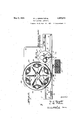
- Fig. l is a frontelevation partially broken away, showing apparatus embodying our invention. j Y.
- Fig. 2 is a top plan.
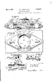
- Fig. 3 is a detail top plan .of a portion of the rotary table showing one of the hood cap skirt contracting and moldin heads iin top plan, portions-being indicatedy dotted lines.
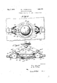
- Fig. 4 is a detail vertical section showing 'one of'said heads in .closed hood cap skirt molding adjustment or position.
- Fig. 5 is a detail vertical section of one-- of said heads showing 'the same in opened position;
- Fig. 7 is'a detail end elevation of one of said heads.
- Fig. 8 is a detail detached view of one of the molding jaws of one of said heads.
- Fig. 9 is a detail section of one of the cap skirt molding devices or heads carried by the table,in open bottle mouth and cap receiving position, the head or mouth portion of a bottle with a hot moldable flaring hood cap thereon being shown in elevation moving up into said molding device and approximately in position to trip the toggle and then continue up to strike the top wall of the device.
- Fig. 10 is a view corresponding to the showing of Fig. 9, butillustrating the toggle broken upwardly, the molding blades in final cap skirt gripping and molding positions, the bottle at its limit of upward movement to which it moved after the initial gripping and molding contact of thev blades with the cap skirt, and the hood cap tightened down on the bottle mouth with the cap skirt in final moldedsecured form.
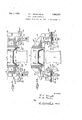
- Fig. 11 is'a detail sectional elevation showing a form'of mechanism for successively while in a temporarily moldable condition
- the elongateddisk heating ,and softening magazine being partially shown'in vertical section with several of the supply'of moldabledisks shown in cross section, a bottle being partially shown elevated with its head in the bottom disk in the magazine, the disk dispensing or transfer mechanism being shown in side elevation at its limit of upward movement and with its fingers in operative disk grasping position.
- Fig. 12 is'a sectional elevation showing the disclosure of Fig. 1l, with the disk dispensing or transfer mechanism at its approximate limit of down-ward movementand its lingers in lwithdrawn Aor inoperative position, the
- the apparatus of our invention is peculiarl adapted and designed to apply hood cap ks to bottle and other container mouths and secure the same thereon by contracting and molding the cap skirts tightly to the bottle necks under the bottle rims, particularly where-such skirts are rendered self securing by the ⁇ resence therein or thereon orl both of a suita le binder rendering the paper material or the like that embodies the binder, normally stiff or hard at climatic or normal temperatures and lastic soft orv moldable at comparativey high temperatures, say at 200 F., more or less within wide limits or bounds.
- the 1particular apparatus illustrated as an examp for purposes of explanation provides a horizontally elongated track or slide- Way yalong which filled bottles can' be suc-' a suitable head or contracting and gripping device takes hold ofthe bottle by its neck and in so doing molds and grips the moldable portion of the skirt tightly against the bottle neck and thusholds the same during the binder setting J and hardening operation after which the hood cap is firmly secured tothe bottle by the set hardened portion of the skirt annularly and radially contracted-under thelpottle rim and tightly hugging the bottle nec
- vat the front this latform provides an elongated horizontal ttle guide or slideway 3, extending from right to left with .reference to Fi .-1 and 2.
- This bottle feedor slideway isunded at the rear by longitudinal vertical lguide wall 4 which-'is adjustable forward y.
- the wall 4 forms the inner or'rear longitudinal. edge wall of the'bottle feed way 3, and, in this example, is L-shape in cross sectionwith itsbase slidably resting on the floor of way3, and said wall is confined and normally held in -position by horizontally swmgable parallel link s 6. arranged to the rear of wall '4, and pivotally joined.
- This back Wall 4 is to maintain the alinement of the- .bottles being advanced along the feedway with respect to other mechanisms, and thel lparallel ruler adjustment, is to permit setting of the back Wall to accommodate runs of bottles of diderent diameters at their bases, such as quarts, pints, and half pints, and maintain the alinement of such bottles with cap applying and securing devices.
- the longitudinal front stop wall or boundary of the bottle feedway is formed by a longitudinal bottle feed slide 8, confined in slidewa 9 in which it can be reciprocated back an forth longitudinally of the bottle feed way to the extent permitted by end stops 10.
- the feed slide 8, can be reciprocated in any suitable manner. or by any suitable means on its bottle feeding and return strokes, althoughthe drawings provide for manual operation of this slide t rough the medium of front handle 11.
- the bottle feed slide is provided with and carries al longitudinal series of preferably uniformly ⁇ spaced bottle propelling fingers 12 that project'laterally from the'slide 8 over and transversely of the bottle feed way.
- Each finger 12 is horizontally swingable, and embodies a vertical hub mounted to rotate on a fixed pin rising from slide 8, a spring constantly acting on the finger to swing the saine to its limit ⁇ of movement toward the right (Fig. 2) and a stop limiting the swing of the finger in that direction sd that the normal position of the nger is at approximate right angles to the bottle feedway and ex- V tending transversely thereof.
- the fingers are free to swing toward the left (Fig.
- the slide is equippedl with three fingers 12, one at the front (right hand) endthereof, one at the rear (lefthand) end thereof, and one midway between 'the endfingers, and these lingers are spaced a arta distance approximately equal to the distance between the b ottle cap receiving sta-- tion and the bottle cap securing ⁇ station.
- the bottles'to right hand end ofthe ottle feedwayand the hood capped bottles are ,delivered 4at the' left hand end of said way.
- the slide is arranged to move on its return stroke toward the rehood cap ed are received at' the ger has slipped past and swung out behind a hood cap secured thereon and bottle, if any, at thehood cap receiving station with a hot flaring skirt cap on its mouth, and the left hand finger has slipped past and swung out behind a b0ttle,-if an having a ocated adjacent the hood cap securing posit-ion.
- the bottle feeding fingers will push the bottles in front thereof forwardly along the bottle feedway, delivering the bottle having ⁇ the secured cap at the delivery end of the way, and the bottle .havingthe flared cap from the receiving station to the delivery station, and the bottle at the receivingend to the cap receiving station. Then on the return and forward strokes' of the slide, the operation will be repeated and the bottles on the way Will be advanced another step.
- the iioor vof the'bottle feed way 3 is formed with a vertical opening normally occupied by a bottle elevating support or plate 14, at its top surface fiush with said floor so that bottles can slide onto and from said-plate, and the same is true of the bottle feed way, at the hood cap securing station ⁇ Where a bottle elevating support or plate '15 is located.
- the bottle elevator 14 is provided with a depending shank 16, coupled to treadle 17, by cord 18, or otherwise, in such manner that depression of the treadle will cause elevation of the elevator or plate 14 and the bottle thereon.
- the bottle elevator 15 has a depending shank 15a, connected by suitable means, such as .cord 15b, to treadle 150, to lift the elevator companion application.
- any suitable hood cap heating and dispensing apparatus for instance such as the hood cap disk heating and dispensing apparatus dsclosed by our pending application Serial No. 58,613 filed Sept. 25, 1925, is arranged above the bottle feed way overhanging the bottle elevator 14 and the bottletheren the example shown, this hood cap dispensing apparatus embodies a cap heating container B having a depending heatedl cap nozzle or vertical bottom mouth Ba, (Fig.
- nozzle Ba overhangs the bottle elevator 14, and is located such a distance above the'same'as to be above'and out of the way ofbottles advancing along the way 3 alined with elevator .'14 and abottle4 thereon, n
- ilaringskirt cap is held on the bottle mouth by any suitable dispensing, devices.
- the cap heating and dispensing container- B is, :in the example shown; lcarried by a rigid post Bd, rising from the supporting frame' or table 1.
- the container B, and its j associated parts are vertically adjustable on the post Bd, with respect to the bottle feed way 3, and normally ixedly held in the desired adjustment, sothat the machine can be set or adjusted to apply hood caps to runs of bottles of different vertical lengths, such as quarts, pints, etc.
- the magazine B, Ba of ourabove mentioned copending application, provides a vertically elongated bore or container c, fora downwardly advancing or feeding multiplicity of binder-carrying paper or fibrous material hood cap disks a, alined in the form of a stack or .pile or if preformed with flaring annular skirts, as shown, said disks are in this example, alined and nested and arranged right side'up with their flaring skirts depending.
- This magazine is provided with heating means to maintain a sufficiently high temperature in said bore to soften or approXithe multiplicity of disks therein under the high temperature required to render such disks moldable.
- hood cap disks in the magazine is replenished by introducing relatively cool disks through the normally closed upper end of said highly heated bore, lhilst temporarily moldable disks are successively dispensed from the bottom or discharge end Ba, of said bore c.
- the long highly heated magazine bore is designed to receive a multiplicityV of hood cap disks and simultaneously expose'all of. such disks to the high temperature to maintain in said bore a supply of such disks in a moldable condition feeding or advancing to- Ward the moldable disk discharge, as moldable disks are dispensed therefrom.
- This method ofbuilding up and maintaining a supply of disks in amoldable condition enables ⁇ :us to dispense moldable disks at a rapid rate of speed not dependent on the relatively long length of time it takes to condition each free ends.
- lingers are in this exam le controlled bytoggles 40a, 48, one set for each linger, with each linger forming a rigid inward extension of its toggle link orlever 40a, the two links or levers 40a, 48, of a toggle being joined at their meeting ends by laterally projecting pivot pin 49.
- the toggles and lingers are carried by and move vertically with an exterior annular slide 57, (Fig.
- brackets 42 liXed to and depending from slide 57, exteriorly of and to-a level below the horizontal plane of the discharge mouth or lower open end of the long magazine bore.
- brackets 42 are approximatel of inverted T form ⁇ each at its inner en longitudinally slotted to provide horizontal guide 47,
- each bracket 42 is also here shown provided with a vertically adjust-able stop 55, to limit the downwardly breaking movement of its toggle.
- Brackets 54 are fixed-to the lower end of the magazine and depend ⁇ theretrom, one for each linger 40, and its toggle.
- Each bracket carries a vertically adjustable vnormally lixed upper stop or abutment 53, and a correspond- 'ing vertically adjustable normally-lixed lower stop. or abutment 53a.
- These two sets of v the exterior slide 57 will start on its upward stroke thereby carrying the lingers 40, and their toggles upwardly with the bottle, the bottle being arranged between the fingers, which are spaced a distance apart to accommodate the bottle and being diametrically oppositely arranged with respect to the bottle.
- said lingers are in downwardly and outwardly retracted or inoperative position (Fig. 12) with the toggles'in upwardly buckled or broken position.
- the bottle b having the flexible paper material hood cap a. centered on its bottle mouth with the hot moldable flaring cap skirt (Fig.
- the disk 20, is carried in elevated position by any suitable means, at such elevation that the bottles sliding along the feedway and over the depressed elevator 15, will pass below and clear the disk, and that the bottle elevated by the elevator 15, will project its head carrying the flared hood cap into the mouth 22 above and alined with the bottle, and into operative position with respect to the bottle grasping and cap'securing means arranged at said mouth.
- any suitable means at such elevation that the bottles sliding along the feedway and over the depressed elevator 15, will pass below and clear the disk, and that the bottle elevated by the elevator 15, will project its head carrying the flared hood cap into the mouth 22 above and alined with the bottle, and into operative position with respect to the bottle grasping and cap'securing means arranged at said mouth.
- I show the disk 2Q carried by a
- the disk has a central vertical hub cessively brought into' vertical alinement with elevator 15 and a bottle thereon as the disk is rotated.
- the disk can be rotated bydany ⁇ suitable means, although in the example illustrated, We provide for rotation of the disk by hand step by step to successively bring the mouths 22 to the front and over the elevator 15, with the disk remaining at rest during the elevation and depression ofthe treadle 150.
- Suitable snap or detent means 15m of a well known structure and operation, can be pro-- vided to yieldingly hold the disk with a mouth 22 alined with elevator 15.
- Each bottle head receiving mouth 22, of the disk 20, is formed by a vertical recess open at the bottom of greater diameter than the capped bottle head or mouth to be vertically received thereby, with the bottom recess or vertical bottle mouth receiving opening 22,
- a fixed top 26 the under side of which forms a seat or stop against which the lflat central top of the hood cap on the bottle fits and against which it is compressed by the annular top edge of the bottle mouth.
- the seat 26,l the under side of which forms a seat or stop against which the lflat central top of the hood cap on the bottle fits and against which it is compressed by the annular top edge of the bottle mouth.
- Each mouth 22 of the disk has associated therewith suitable bottle holding or grip-- ping and hood cap skirt compressing and securing means.
- a pair of alined plates 28 overlapping and joining the two plates 27 and arranged diametrically opposite 22and slidable radially thereof in opposite directions toward and from each other and the vertical axis of said mouth simultaneously with the corresponding movements ci lates '27- i nh op sing inner or operative ends of theblades 27 are correspondingly transversely concaved, and bevelled at their side faces, to form a pair' of usually similar segmental cap skirt molding and compressing blade edges 27a, that in radius correspon approximately to each other and to the radius of the bottle neck to be grasped thereby and that will extend from opposite sides partially around said neck, and the operative ed e portions of the plates 28, are approximate y similar to each other and correspondingly concaved and bevelled -to form com ressing and molding vertically narrow bla e edges 28a, to-bridge the gaps between the opposite -of blade
- operativebladeedges 27a, 28a there are four operativebladeedges 27a, 28a, each occup ing approximately ninety degrees of the circ e the entrance to the mouth 22, and movable radially of said circle along radii approximately ninet degrees apart.
- the p ates or blades 28, form, arallel with, over? lapping and carried by t e two plates 27, to complete the circle of blade edges around the mouth.
- 27 b rigi with and epending from plates 27,*i and extending loosely through vertical segmental cam slots 281, in the opposite end portions of blades 28, andarranged longitudinally thereof.
- the arrangement is such that when the two x blades are moved 'in opposite directions so ,that their blade edges 27a, approach each other, the pins 27?), supporting blades 28 from plates 27, will move toward the inner-ends of the curved' cam slots 28, and will force the twoblades 28 inwardly in opposite directions toward each other so that t with the inward radial movement plete circle of compressing gripping .blade each otherwith respect to mouth thisv example,
- the plates 27 move in a common plane, and the blades 28 also move in a common plane that is parallel with the plane in which plates 27 move, and as close thereto as possible; and in the blade operating force is appliedthrough, plates 27.
- the two plates 27, are provided with up-standing lugs or posts 30, rigid therewith and projecting upwardly through lelongated slots 31 through disk 20, and radially arranged with respect to mouth 22. 1 i'lheseposts 30 carry the blades 27, 28, and are. upheld by plates 32, slida'ble on the ton face of the dfsk 20.
- Suitable springlat is constantly exerting its tension anr power to force the blades 27,28', to their limits of inward movement, i. e. .to bottle gripping and hood'cap skirt compressing position.
- springs 33 extending between, connectin an at their ends secured to the posts 30, an dis- ⁇ tended to exert their tension to pull the posts 30 toward each otherand consequently o rate to move the blades to their limits o inward movement.
- Suitable means is provided by which the posts can be forced apart against the tension of said .springs to-open the blades 27, 28, and by which the parts canbe held in such positions.
- i f c For. instance, we show the two posts 30 connected by a toggle lever-arrangement accessible at the top side of the disk 20, and above the elevated stop wall.26 that forms the top of the mouth or recess 22.
- This toggle device consists of two levers 34 joined at their overlapping-inner ends by transverse pivot 34a, one lever at its outer end joined to one post 30 by transverse pivot 346, and the other lever at its outer end )oined to the other post 30, by Vanother transverse pivot 345.
- the arrangement y'of the toggle is such that moved outwardly, to open the a pair.
- the toggle will thus hold the parts, until the toggle is tripped by moving the joint or center thereof upwardly past the dead center to start the upward buckling .or breaking of the toggle under the action of the springs. The instant the toggle joint passes -up beyond the dead pending ⁇ therefrom.
- each lever 34 of al center the springs will break the toggle upwardly with a snap and force the blades quickly inwardly to perform their bottlegripplng andcap skirt molding operation.
- the toggle can-be thus tripped by hand or any suitable mechanism canbe provided for this purpose.
- Any suitable mechanism or means can be provided for depressing the toggles to locked opened position at or below the dead center
- means can be provided whereby the entrance of a bottle head into a mouthV 22, f the disk 20, will cause automatic upward breaking of the toggle of said mouth 22 andfconsequent closing in operative movement of the blades 27, 28 against the cap skirt of the upwardly moving bottle head in the mouth.
- a cap skirt molding head that embodies a circle of vertically narrow blade edges that press radially inward completely around the circle of the cap skirt to tightly compress the skirt against the bottle neck on an annular line completely surrounding the neck. Furthermore this molding' compressing blade action is under yieldingspring pressure which avoids bottle breakage and allows for unbottle necks, and also maintains the desiredtight grip of the blade edges on the cap skirt during the time that the blades remain in gripping position on the cap and bottle neck while the cap skirt is coolingand setting.
- the rotary disk 20 with a plurality of mouths 22 and associated grippingand molding devices, and elevate this diskiso that itcan carry a multiplicity of bottles suspended therefrom and traveling therewith elevated above the table and feed- .wav guides etc. i
- the bottles .after being carried ⁇ around by the disk, are successively discharged from the disk at the point desired, for oil-taking from the apparatus for delivery.
- Apparatus for hood capping containers comprising means for delivering onto a bottle mouth, a paper material hood cap. having a flaring skirt embodying a binder in a mo dable condition, hood cap skirt molding mech anism, associated with said means, for compressing and molding said skirt against and completely around the bottle neck, and means for advancing, said mechanism with the bottle while continuing to hold the moldable cap skirt compressed until set to permanent secured condition.
- Apparatus for applying1 and securing paper material hood caps, t at have their skirts rendered self-securing by a binder, to and enclosing a bottle mouth comprising means for rendering the 'skirts of said caps teinporarily'soft and moldable and for applying the moldable-skirt cap to the head of a bottle located at a Cep receiving station, a cap skirt molding an compressin device for radially compressing such molda le ⁇ skirt against and completel around the bottle neck while the bottle is ooatedat a cap molding station, and for thus holding the same until set to stii bottle cap securing form, and means for advancing the bottle from the cap 3.
- Apparatus for applying paper material hood caps carrying a binder, to and securing the same on bottle heads, com risin an elongated bottle feedway, means or a vancing bottles along said way to a cap receiving station and therefrom to a c ap securing station, bottle elevators at said stations, hood cap skirt softening and hood cap dispensing mechanism overhanging the botsaid cap receiving station, and
- overhanging curin station for contracting the moldable cap s irt on the bottle head and thus holding the seme unttilit. 1 te 1 4.
- ppara us or ap yin paper ma ma hood caps the skirts ofpwhii carry abinder rendering the caps self-securing;- to and vsecuring the same on bottle mout comprising an elongated bottle feedway, a hood cap to fall therebe.
- said apparatus comprising 'a ring of blades having segmental cap skirt molding and compressing edges, and means for expanding and contracting said ring of blades, including a spring pressed toggle for holding said ring expanded and where y said blades can be released for .contracting said ring.
- Apparatus for rendering sheet fibrous material binder-carrying hoodcap disks moldable byheat and hood capping bottles therewith including meansfor rendering a supply consisting of a multiplicity of such disks temporarily moldable by heat; means for successively bringing together moldable disks from said supply'and the heads of bottles supported in upright position; a succession of mechanisms for gathering the skirt 35 portions of the hot moldable disks on successive bottle heads and contracting the same circumferentially inwardly and radially under the bottle head rims and thus holding the saine, in secured hood cap form until set by cooling; and means for advancing the hood capped bottles in upright position with said mechanisms contracting the caps on the 'heads thereof while said hood caps are setting to stiff securing condition.
- Apparatus for heating sheet fibrous material binder-carrying hood cap disks to render them moldable and hood capping bottles with the moldable disks saidy apparatus including means for supporting and advancing bottles in upright position; means for rendering said disks moldable byhea-t; means for vertically bringing together the head of anupright bottle and a hot moldable disk; mechanism for gathering the moldable skirt portion of the disk on the bottle head down.
- Apparatus for heating sheet fibrous material-binder-carrying hood cap disks to render them moldable and hood capping bottles with the moldable disks said apparatus including means for supporting and advancing bottles in upright position; means for rendering said disks ⁇ moldable by heat; means for vertically bringing together the head of an upright bottle and a hot moldable disk;
- Apparatus for heating sheet fibrous loo' material binder-carrying hood cap disks to render them moldable and hood capping bot'- tles with the moldable disks said apparatus includingmeans for supporting and advancing bottles in upright position; means for rendering said disks moldable by heat; means I for-vertically bringing together the head of an upright bottle and a hot -moldable disk; mechanism for gathering the moldablejskirt portion of the disk on the bottle head down# wardly and inwardly and contracting the saine' in under the lbottle head to hood cap securing position and thus maintaining the skirt until set to stiff securing condition; and means for moving the bottle and mechanism together forwardly to the .hood capped bottle discharge while the hood capis setting, means being provided wherebythe hoodcapped up- A right bottle is releasedafrom said mechanism, 5 when at the bottle. ;di scharge. v
- Apparatus for rendering binder-carrying hood cap disks moldable and for hood capping bottles with said moldable disks; including bottle supporting means for elevating upright bottles to carry the heads thereof into overhanging hood cap disk molding means movable forwardly with the bottles during the -hood cap moldin and settin operations; and overhanging ood ca dis molding means embodying a horizonta y rotating carrier provided with and advancing a series-of hood cap disk molding and contracting mechanisms to successively receive the headspf bottles elevated thereinto and to move forward -with the bottles during' the opand holding, the same thereto until set thereon.
- a horizontally advancing carrier for supporting and advancing a series of bottles while suspended by their heads from said carrier; said carrier provided with a series of expansible and lcontracting l,rings to vertically receive bottle heads carrying said disks in hot moldable condition and gather and'contract the skirt portions of said disks to and under the bottle head rims and to thus hold the same until set while advancing with the bottles, said rings constituting the means whereby the bottles are grasped and suspended from the carrier by the bottle heads; and means for supportbottles in uprightposition for vertical.
- Apparatus for hood capping bottles that includes means for maintaining a multiplicity of sheet fibrous material hood caps having flaring flexible skirts in an advancing procession, to provide a supply of said caps for quick successive delivery, means for successively dispensing said flexible skirted caps material hood caps having flexible flaringskirts arranged in succession to provide a hood cap supply for quick successive delivery and causing said supply of hood caps to advance as caps are delivered therefrom; means for holding successive caps with their open bottoms positioned to receive successive bottle heads for deposit thereon with theirskiits depending around the bottle heads; and several hood cap skirt contracting mechanisms movable forward in succession with the bottles from said skirt contracting station to i 'said bottle discharge station, and each receiving a bottle head loosely carrying a H aring skirted hood cap'at said skirt contracting station for contracting the flexible skirt for securing under the bottle head-"rim and adapted to discharge the bottle carrying a secured hood cap at said discharge station.
- hood cap skirt con tract-ing and compressing annular clamps each adapted when expanded to receive the head' of an upright bottle carrying a sheet fibrous materialhood cap having its flexible skirt depending around said head, and adaptmeans; means whereby said holding means is ed to contract in diameter around said skirt and forcibl drive the same to secured form under the ottle head rim and against the bottle surface; ⁇ spring means constantly acting on said clamp to forcibly contract the same; holding means to maintain said clamp expanded against the tension of saidspring adapted to suddenly release said spring meansmo forcibly contract lsaid clamp to gather and contract the cap .skirt and compress the ⁇ same against the bottle surface .with a hammering blow completely Varound the circle of the's'kirt.
- Apparatus'for hood capping bottles including means' 'to provide upright successive bottleswith sheet material hood caps v having fhaxible Haring skirtsloosely centered onfthe heads thereof with their'skirts depending around said heads; a succession of hood cap skirt gathering and compressing annular expanding and contracting clamps each when expanded adapted to receive the head of a bottle carrying a daring skirt hood Lisis cap and adapted to contract annularly and radially around said skirt and contract and.
- Apparatus for hood capping containers comprising means for providing the head of a container having a-rim with a fibrous material hood cap the binder carrying flaring skirt of which isin a temporarily moldable condition; hood cap skirt molding mechanism for pressing and molding said temporarily moldable skirtto and under said bottle 'head rim, and means for advancing said mechanism and said bottle with said mechanism holding the cap skirt molded undepending flexible skirts; in combination;
- Apparatus for applyin exible sheet paper material hood caps skirts to upright bottles the heads of which have exterior rims with the flaring cap skirtsv depending around -said heads for contraction and pressing to secured position under r aving flaring said rims; said apparatus-comprising means for advancing a procession of upright bottles; an elevated supply for a multiplicity o'f said hood caps; means for successively dispensing said hood caps from said supply onto the headsof successive bottles of said procession with the flexible cap skirts dependl A ing around ythe bottleheadsgand means for 1,23 Y
- Apparatus for hood capping bottles 'with iexible sheet material hood caps having Haring iexible annularskirts comprising mechanism for supporting and advancing a procession of successive upright bottles along an elongated path and for successively elevating such upright bottles; and means for maintaining and advancing a multiplicity or supply of said Haring skirt hood caps;
- hood capping containers clude providing a multiplicity of such hood cap disks in a procession and subjecting such procession to conditions whereby such disks are reduced to and maintained in said temporarily moldable state and thereby providing a supply'of such moldable disks for quick successive delivery for hood capping advancing such supply of moldable disks to present successive moldable disks for delivery; bringing together successive moldable disks from said supply andthe heads of successive containers of a procession; successively molding such disks to securing form on the heads of such containers; and advancing such containers in procession along an extended path to a hood capped container discharge While holding the molded caps in secured form until i set. 35.
- hood capping containers In the art of hood capping containers,
- steps which include maintaining a multiplicity of hood cap disks in a temporarily moldable condition'by heat to provide a constant supply of such disks, causing said disks to advance in procession; bringing together the heads of successive containers and successive moldable disks from said supply for securing on the respective heads; molding the still moldable hood cap disks on the contained heads; and advancing a succession of said hood capped containers toa discharge station and holding the caps on said succession of containers While setting inv molded form.
Landscapes
- Closures For Containers (AREA)
Description
may 3, i932. w. L.' wRlGi-'r ETAL 85773 HOOD CAPPING CONTAINER OriginallFild Sept. 26,- 1925 6 Sheets-Sheet l May 3, 1932;. w. L. WRIGHT ET AL HOOD `OAPPING CONTAINER Original Fle Sept. 26, 1925 6 Sheets-Sheet' 2 gnentou May 3, 1.932., w. WRIGHT ET AL 1,857,073
l oo CAPPING CONTAINER origial Filed Sept.' 26, 1925 6 Sheets-sheet :s
| I m v Quorum* May 3, 1932. w. L.. WRIGHT E 'r AL A 857073 HOOD CAPPING CONTAINER Original Filed Sept. 26, 1925 6 Sheets- Sheet 4V 120 ga-'rw Il. EMI.
28 276 Z7 am am MW 39 i933 w. l.. WRIGHT l-:r AL y 1,857,073
HooD CAPPING CONTAINER Original Filed sept'. 2e, 1925 6 sheets-sneer 5 ay 3, 1932. w. L. WRIGHT E1' AL l857073 Hoon CAPPING CONTAINER K Original Filed Sept. 26. 1925 6'SheetS-Sheef. 6
, contracted secured form until set.
Patented May 3, 1932 UNITE-D STATES',
PATENT OFFICE WILBUR L. WRIGHT .AND LEE D. PIERCE, OF FULTON, NE'Wl YORK, VASSIG'NORS T0 ,OSWEGO FALLS CORPORATION, 0F FULTONVNEW YORK, A CORPORATION OF NEW YORK HOOD CAPPING CONTAINER Application led September 26, A1925, Serial No. 58,780; Renewed Hatch I, 1931.
This invention relates to the art of applying and securing hood cap disks of paper or su stantially equivalent material to' containers to cover and enclose the mouth portions thereof; and the objects andnature of our invention will be readily understood by those skilled in the art in the light of the following explanations of the accompanying drawings that illustrate what we now believe to be thepreferred mechanical expression or embodi-- ment of our invention from among other forms, constructions and arrangements within the spirit and scope thereof.
An object of the invention is to speed up the operation of applying sheet fibrous material hood caps having Lflexible flaring skirts to and securing them 011 the heads of upright `containers such as bottle heads having eXterior rims under which the flexible skirts are contracted and pressed for securing. i
A further object of the invention is to providevimproved apparatus for hood .capping containers with temporarily moldable hood cap disks and for holding the annular portions of said disks drawn downwardly and contracted inwardly on the bottle heads, in
With these and other objects in view, the invention consists in certain novel features of construction, and in arrangements and combinations as more 4fully and particularly set forth and specified hereinafter.
Referring toI the accompanying drawings forming a part hereof:
Fig. l is a frontelevation partially broken away, showing apparatus embodying our invention. j Y.
Fig. 2 is a top plan.
Fig. 3 is a detail top plan .of a portion of the rotary table showing one of the hood cap skirt contracting and moldin heads iin top plan, portions-being indicatedy dotted lines.
Fig. 4 is a detail vertical section showing 'one of'said heads in .closed hood cap skirt molding adjustment or position. Fig. 5 is a detail vertical section of one-- of said heads showing 'the same in opened position;
is afdetailbottom plan of one of Flg. 6 saidl eadswhen in opened position: ,1
Fig. 7 is'a detail end elevation of one of said heads.
Fig. 8 is a detail detached view of one of the molding jaws of one of said heads.
Fig. 9 is a detail section of one of the cap skirt molding devices or heads carried by the table,in open bottle mouth and cap receiving position, the head or mouth portion of a bottle with a hot moldable flaring hood cap thereon being shown in elevation moving up into said molding device and approximately in position to trip the toggle and then continue up to strike the top wall of the device.
Fig. 10 is a view corresponding to the showing of Fig. 9, butillustrating the toggle broken upwardly, the molding blades in final cap skirt gripping and molding positions, the bottle at its limit of upward movement to which it moved after the initial gripping and molding contact of thev blades with the cap skirt, and the hood cap tightened down on the bottle mouth with the cap skirt in final moldedsecured form.
Fig. 11 is'a detail sectional elevation showing a form'of mechanism for successively while in a temporarily moldable condition,
downwardly from the procession or supply of temporarily moldable disks inthe elongated heating magiazine wherein said supply or procession -of moldable disks advance downwardly, and ultimately releasing such disks on the heads of successive bottles, the elongateddisk heating ,and softening magazine being partially shown'in vertical section with several of the supply'of moldabledisks shown in cross section, a bottle being partially shown elevated with its head in the bottom disk in the magazine, the disk dispensing or transfer mechanism being shown in side elevation at its limit of upward movement and with its fingers in operative disk grasping position. D l
Fig. 12 is'a sectional elevation showing the disclosure of Fig. 1l, with the disk dispensing or transfer mechanism at its approximate limit of down-ward movementand its lingers in lwithdrawn Aor inoperative position, the
bottle being shown on its upward movement to receive a temporarily moldable bindercarrying hood cap disk.
- The apparatus of our invention is peculiarl adapted and designed to apply hood cap ks to bottle and other container mouths and secure the same thereon by contracting and molding the cap skirts tightly to the bottle necks under the bottle rims, particularly where-such skirts are rendered self securing by the` resence therein or thereon orl both of a suita le binder rendering the paper material or the like that embodies the binder, normally stiff or hard at climatic or normal temperatures and lastic soft orv moldable at comparativey high temperatures, say at 200 F., more or less within wide limits or bounds.
The 1particular apparatus illustrated as an examp for purposes of explanation, provides a horizontally elongated track or slide- Way yalong which filled bottles can' be suc-' a suitable head or contracting and gripping device takes hold ofthe bottle by its neck and in so doing molds and grips the moldable portion of the skirt tightly against the bottle neck and thusholds the same during the binder setting J and hardening operation after which the hood cap is firmly secured tothe bottle by the set hardened portion of the skirt annularly and radially contracted-under thelpottle rim and tightly hugging the bottle nec For instance, we show an elevated horizontal platform 1, supported by any suitable means, such-as one or more pedestalsv2, and
" vat the front this latform provides an elongated horizontal ttle guide or slideway 3, extending from right to left with .reference to Fi .-1 and 2. This bottle feedor slideway isunded at the rear by longitudinal vertical lguide wall 4 which-'is adjustable forward y. The wall 4, forms the inner or'rear longitudinal. edge wall of the'bottle feed way 3, and, in this example, is L-shape in cross sectionwith itsbase slidably resting on the floor of way3, and said wall is confined and normally held in -position by horizontally swmgable parallel link s 6. arranged to the rear of wall '4, and pivotally joined. thereto and to' the platform, to provide a parallel rulerl arrangement, so thattheA wall 4 can be pushed ack b hand or canbe pulled forwardly, while t e parallel. swinging links maintain the wall 4 parallel with the longi- I tudinal axis ofthe bottle Way 3. This back Wall 4, is to maintain the alinement of the- .bottles being advanced along the feedway with respect to other mechanisms, and thel lparallel ruler adjustment, is to permit setting of the back Wall to accommodate runs of bottles of diderent diameters at their bases, such as quarts, pints, and half pints, and maintain the alinement of such bottles with cap applying and securing devices.I i
The longitudinal front stop wall or boundary of the bottle feedway is formed by a longitudinal bottle feed slide 8, confined in slidewa 9 in which it can be reciprocated back an forth longitudinally of the bottle feed way to the extent permitted by end stops 10. The feed slide 8, can be reciprocated in any suitable manner. or by any suitable means on its bottle feeding and return strokes, althoughthe drawings provide for manual operation of this slide t rough the medium of front handle 11. v
The bottle feed slide is provided with and carries al longitudinal series of preferably uniformly `spaced bottle propelling fingers 12 that project'laterally from the'slide 8 over and transversely of the bottle feed way. Each finger 12 is horizontally swingable, and embodies a vertical hub mounted to rotate on a fixed pin rising from slide 8, a spring constantly acting on the finger to swing the saine to its limit `of movement toward the right (Fig. 2) and a stop limiting the swing of the finger in that direction sd that the normal position of the nger is at approximate right angles to the bottle feedway and ex- V tending transversely thereof. The fingers are free to swing toward the left (Fig. 2) against the tension of their springs, so as to slip past bottles on the feedway when the slide is making its return stroke toward the right (Fig52) but are rigid with the slide against swing toward the right beyond their normal operative ositions (Fig. 2) so as to ush the bottles orward toward the' left w en the slide is making its operative bottle advancing stroke toward the left (Fig. 2). p
' In the 'particularexample illustrated for purposes ofexplanation, the slide is equippedl with three fingers 12, one at the front (right hand) endthereof, one at the rear (lefthand) end thereof, and one midway between 'the endfingers, and these lingers are spaced a arta distance approximately equal to the distance between the b ottle cap receiving sta-- tion and the bottle cap securing` station.
However, 'we'do not wish to s limit our invention.
In the articular example illustrated, the bottles'to right hand end ofthe ottle feedwayand the hood capped bottles are ,delivered 4at the' left hand end of said way. The slide is arranged to move on its return stroke toward the rehood cap ed are received at' the ger has slipped past and swung out behind a hood cap secured thereon and bottle, if any, at thehood cap receiving station with a hot flaring skirt cap on its mouth, and the left hand finger has slipped past and swung out behind a b0ttle,-if an having a ocated adjacent the hood cap securing posit-ion. Then when the slide is moged to the left on its operative stroke, the bottle feeding fingers, will push the bottles in front thereof forwardly along the bottle feedway, delivering the bottle having `the secured cap at the delivery end of the way, and the bottle .havingthe flared cap from the receiving station to the delivery station, and the bottle at the receivingend to the cap receiving station. Then on the return and forward strokes' of the slide, the operation will be repeated and the bottles on the way Will be advanced another step.
At the hood cap receiving station, the iioor vof the'bottle feed way 3, is formed with a vertical opening normally occupied by a bottle elevating support or plate 14, at its top surface fiush with said floor so that bottles can slide onto and from said-plate, and the same is true of the bottle feed way, at the hood cap securing station `Where a bottle elevating support or plate '15 is located.
The bottle elevator 14 is provided with a depending shank 16, coupled to treadle 17, by cord 18, or otherwise, in such manner that depression of the treadle will cause elevation of the elevator or plate 14 and the bottle thereon.
15 and control the descent thereof.
Any suitable hood cap heating and dispensing apparatus, for instance such as the hood cap disk heating and dispensing apparatus dsclosed by our pending application Serial No. 58,613 filed Sept. 25, 1925, is arranged above the bottle feed way overhanging the bottle elevator 14 and the bottletheren the example shown, this hood cap dispensing apparatus embodies a cap heating container B having a depending heatedl cap nozzle or vertical bottom mouth Ba, (Fig. l), and cap dispensing device Bb, such as disclosed by our above mentloned The bottom mouth of nozzle Ba, overhangs the bottle elevator 14, and is located such a distance above the'same'as to be above'and out of the way ofbottles advancing along the way 3 alined with elevator .'14 and abottle4 thereon, n
and is so arranged that the mouth or top of; a bottle on and elevated byelevator `14-vvil1 enter thevertical mouth of said discharge nozzle and fit up into a.x hot flaring skirt 'hood held in 'position lin the nozzle to receivel the bottle mouth. t When the treadle is released, the bottle having the hood cap properly located on its mouth with the Haring skirt-in moldable position, descends with the elevator. l During the descent of the bottle, the
ilaringskirt cap is held on the bottle mouth by any suitable dispensing, devices.
The cap heating and dispensing container- B, is, :in the example shown; lcarried by a rigid post Bd, rising from the supporting frame' or table 1. The container B, and its j associated parts are vertically adjustable on the post Bd, with respect to the bottle feed way 3, and normally ixedly held in the desired adjustment, sothat the machine can be set or adjusted to apply hood caps to runs of bottles of different vertical lengths, such as quarts, pints, etc.
The magazine B, Ba, of ourabove mentioned copending application, provides a vertically elongated bore or container c, fora downwardly advancing or feeding multiplicity of binder-carrying paper or fibrous material hood cap disks a, alined in the form of a stack or .pile or if preformed with flaring annular skirts, as shown, said disks are in this example, alined and nested and arranged right side'up with their flaring skirts depending. This magazine is provided with heating means to maintain a sufficiently high temperature in said bore to soften or approXithe multiplicity of disks therein under the high temperature required to render such disks moldable. The supply of hood cap disks in the magazine, is replenished by introducing relatively cool disks through the normally closed upper end of said highly heated bore, lWhile temporarily moldable disks are successively dispensed from the bottom or discharge end Ba, of said bore c.
The long highly heated magazine bore is designed to receive a multiplicityV of hood cap disks and simultaneously expose'all of. such disks to the high temperature to maintain in said bore a supply of such disks in a moldable condition feeding or advancing to- Ward the moldable disk discharge, as moldable disks are dispensed therefrom. This method ofbuilding up and maintaining a supply of disks in amoldable condition enables `:us to dispense moldable disks at a rapid rate of speed not dependent on the relatively long length of time it takes to condition each free ends. These lingers are in this exam le controlled bytoggles 40a, 48, one set for each linger, with each linger forming a rigid inward extension of its toggle link orlever 40a, the two links or levers 40a, 48, of a toggle being joined at their meeting ends by laterally projecting pivot pin 49. The toggles and lingers are carried by and move vertically with an exterior annular slide 57, (Fig. 1) vertically movable on the heated lower or discharge portion of the hood cap disk magazine, raised by and permitted to drop with the' slide 16, of bottle elevating stool 14, through the medium' of a rear vertical slidel post 58, at its upper end operatively coupled to slide 57 as by fork 459,`and at its lower end having normally fixed and vertically adjustable sleeve 60, through which slide 16, is vertically movable; a stop 61, normally fixed to slide 16, being arranged to strike and lift sleeve 60, when slide 16, has advanced a certain distance upwardly on its bottle elevating stroke, and thereby lift slide post 58,
and slide`57, and permit said parts 57, 58,
60, to drop when slide 16, descends. The hood cap disk grasping and releasing lingers 40, andtheir operating toggles, are carried by brackets 42, liXed to and depending from slide 57, exteriorly of and to-a level below the horizontal plane of the discharge mouth or lower open end of the long magazine bore. These brackets are approximatel of inverted T form` each at its inner en longitudinally slotted to provide horizontal guide 47,
for the laterally projecting axis or fulcrum pin 50, of the toggle carried by such bracket, the opposite end of the toggle being pivoted to the bracket by pivot pin 48a. The laterally projecting ends of the two pins 48a, 50, of each toggle'being preferably connected by retractile coiled springl (Fig. 12) constantly exerting its tension to break the toggle either upwardly or downwardly and withdraw the pin 50, to its limit of outward .movement in closed-end slot or guideway 47. Each bracket 42, is also here shown provided with a vertically adjust-able stop 55, to limit the downwardly breaking movement of its toggle. Brackets 54, are fixed-to the lower end of the magazine and depend `theretrom, one for each linger 40, and its toggle. Each bracket carries a vertically adjustable vnormally lixed upper stop or abutment 53, and a correspond- 'ing vertically adjustable normally-lixed lower stop. or abutment 53a. These two sets of v the exterior slide 57, will start on its upward stroke thereby carrying the lingers 40, and their toggles upwardly with the bottle, the bottle being arranged between the fingers, which are spaced a distance apart to accommodate the bottle and being diametrically oppositely arranged with respect to the bottle. During this upward movement of the lingers 40, with the rising bottle, said lingers are in downwardly and outwardly retracted or inoperative position (Fig. 12) with the toggles'in upwardly buckled or broken position. Y
As the head of the ascending bottle enters the bottom moldable cap a, in magazine bore c, the projecting center pivot pins 49, of the ascending upwardly-broken toggles engage, the top lixed stops 53, and said toggles vare straightened out, thereby rocking levers 40a, on pins 50, to swing lingers 40. upwardly to positions with their free ends upstanding on opposite sides of the bottle head, to pass up within the depending skirt of the bottom hood cap that the bottle head is then entering. As the head ofv the ascending bottle continues ,upwardly and seats within and against the top of the bottom hood cap a, the stopsv 53, resist upward movement of the toggle pins 49, and said toggle pins are depressed downwardly beyond the toggle dead i center lines, whereupon the springs 51, cause said toggles to break downwardly against stops 55, (Fig. 11) thereby swinging the upstanding fingers 40, within the cap skirt outwardly against said skirt to take hold of or grasp the same, whereupon the bottle and lingers come to rest having reached their ward movement by engagement with the fixed lower stops 53a, as the toggles and bottle continue down the distance necessary to straighten out the tog les and press the pins 49,' upwardlybeyon vthe dead center lines, whereupon the fingers 40, are swung downwardly and outwardly from and releasing the cap on the bottle head, and the toggles and fingers come to rest in the positions shownby Fig. 12. .The bottle with the moldable. hood cap resting on and depending around its head, continues on its downward movement until the stool 14, comes to rest at the level of guideway floor 3..
We do not wish to limit allfeatures of our container hood capping invention claimed herein to the hereby disclosed particular method of and mechanisms for conditioning and maintaining a supply or procession of temporarily moldable binder-carrying hood cap disks and for successively dispensing the same to bottle heads for hood capping, and such method and mechanisms are-not specifically or per se claimed herein but are so claimed in our said copending application filed September 25,1925, Serial No. 58,613.
The bottle b, having the flexible paper material hood cap a. centered on its bottle mouth with the hot moldable flaring cap skirt (Fig.
9) depending at theexterior thereof and surrounding ts rim, is then /advanced by the slide 8, by hand, or otherwise, to the cap securing station, at which it is left standing on the bottle elevator 15.
When a bottle is elevated to receive a mold- `able hood cap, a bottle on elevatorl. is,
ential or annular series of vertical downwardly opening bottle neck receivingJ mouths 22. and bottle holding and hood cap skirt clamping or compressingheads or devices.
The disk 20, is carried in elevated position by any suitable means, at such elevation that the bottles sliding along the feedway and over the depressed elevator 15, will pass below and clear the disk, and that the bottle elevated by the elevator 15, will project its head carrying the flared hood cap into the mouth 22 above and alined with the bottle, and into operative position with respect to the bottle grasping and cap'securing means arranged at said mouth. Hence, as bottles of different capacities vary in vertical length, means are provided for adjusting the disk 20, and holding the same at the desired elevation.
For instance, I show the disk 2Q carried by a The disk has a central vertical hub cessively brought into' vertical alinement with elevator 15 and a bottle thereon as the disk is rotated.
The disk can be rotated bydany `suitable means, although in the example illustrated, We provide for rotation of the disk by hand step by step to successively bring the mouths 22 to the front and over the elevator 15, with the disk remaining at rest during the elevation and depression ofthe treadle 150. Suitable snap or detent means 15m, of a well known structure and operation, can be pro-- vided to yieldingly hold the disk with a mouth 22 alined with elevator 15.
Each bottle head receiving mouth 22, of the disk 20, is formed by a vertical recess open at the bottom of greater diameter than the capped bottle head or mouth to be vertically received thereby, with the bottom recess or vertical bottle mouth receiving opening 22,
provided at the top with a fixed top 26, the under side of which forms a seat or stop against which the lflat central top of the hood cap on the bottle fits and against which it is compressed by the annular top edge of the bottle mouth. In other words, the seat 26,l
limits'the upward movement of the bottle in the mouth'22 of the disk 20.
Each mouth 22 of the disk has associated therewith suitable bottle holding or grip-- ping and hood cap skirt compressing and securing means.
For instance, in the particular example il.-
lustrated, we arrange a series of movable bottle holding and cap skirt gripping blades at the under side of the disk 20, whereby the entrance to the mouth 22, can be annularly or circumferentially enlarged to permit free entrance of the capped bottle head or mouth portion into the mouth 22, andwhereby said entrance can be contracted to a diameter less than the overall diameter of the exterior rim portion of the capped bottle head in the mouth to cause the blades to grip and hold the bottle at its contracted portion below said rim and to radially and annularly mold and compress the depending binder carrying portion of the hotcap to and tightly against the .contracted bottle head or neck -portion below the bottle mouth rim, and to thus hold side of disk 2O at opposite sides of the 22 and slidable radially thereof in opposite` blades consist of a pair of diametrically opposite alined plates 27 arranged at the undel;
mout
directions toward and from each other and the vertical axis of the'mouth 22,. and a pair of alined plates 28 overlapping and joining the two plates 27 and arranged diametrically opposite 22and slidable radially thereof in opposite directions toward and from each other and the vertical axis of said mouth simultaneously with the corresponding movements ci lates '27- i nh op sing inner or operative ends of theblades 27 are correspondingly transversely concaved, and bevelled at their side faces, to form a pair' of usually similar segmental cap skirt molding and compressing blade edges 27a, that in radius correspon approximately to each other and to the radius of the bottle neck to be grasped thereby and that will extend from opposite sides partially around said neck, and the operative ed e portions of the plates 28, are approximate y similar to each other and correspondingly concaved and bevelled -to form com ressing and molding vertically narrow bla e edges 28a, to-bridge the gaps between the opposite -of blades around are segmental in ends of the segmental blade edges 27a, and to complete the circle of blade edges around the bottle neck. Y
In this articular example, there are four operativebladeedges 27a, 28a, each occup ing approximately ninety degrees of the circ e the entrance to the mouth 22, and movable radially of said circle along radii approximately ninet degrees apart.
In this example the p ates or blades 28, form, arallel with, over? lapping and carried by t e two plates 27, to complete the circle of blade edges around the mouth. We show the blades' 28, connecting the corresponding inner corners ot the plates 27 and arran ed below `the same and hung l therefrom b I eaded pins or rivets. 27 b rigi with and epending from plates 27,*i and extending loosely through vertical segmental cam slots 281, in the opposite end portions of blades 28, andarranged longitudinally thereof.
The arrangement is such that when the two x blades are moved 'in opposite directions so ,that their blade edges 27a, approach each other, the pins 27?), supporting blades 28 from plates 27, will move toward the inner-ends of the curved' cam slots 28, and will force the twoblades 28 inwardly in opposite directions toward each other so that t with the inward radial movement plete circle of compressing gripping .blade each otherwith respect to mouth thisv example,
e operative inward radial movement of the blade edges. 28a, will take place approximately simul taneously l of the blade edges 27 a, and approximately to vthe same extent or distance, to form a comigssmv edges that'close in around the moldable skirt of the hood cap andcompress and mold the same against the bottle neck completely around the'circle thereof. When theplates 27 move in the opposite directions, i. e. away jfrom each other, the blades 28, are correspondingly throat or entrance'to mouth 22, by the action of pins 271) and cam slots 2,86.
l Various means can be employed to provide lan annular series of se mental blade edges to form a com lete circ e of 4blade edges to close in aroun the moldable -ca skirt' and clampand compress the same an to open to release the same and various operatin means can be employed to cause such bla e edges to move to opened and closed positions, and we do not wish to limit ourselves to the exact connected blade arrangement shown.
In the particular example illustrated, the plates 27 move in a common plane, and the blades 28 also move in a common plane that is parallel with the plane in which plates 27 move, and as close thereto as possible; and in the blade operating force is appliedthrough, plates 27. The two plates 27, are provided with up-standing lugs or posts 30, rigid therewith and projecting upwardly through lelongated slots 31 through disk 20, and radially arranged with respect to mouth 22. 1 i'lheseposts 30 carry the blades 27, 28, and are. upheld by plates 32, slida'ble on the ton face of the dfsk 20.
Suitable springl mecanism is constantly exerting its tension anr power to force the blades 27,28', to their limits of inward movement, i. e. .to bottle gripping and hood'cap skirt compressing position. For instance, we show springs 33 extending between, connectin an at their ends secured to the posts 30, an dis-` tended to exert their tension to pull the posts 30 toward each otherand consequently o rate to move the blades to their limits o inward movement.A
Suitable means is provided by which the posts can be forced apart against the tension of said .springs to-open the blades 27, 28, and by which the parts canbe held in such positions. i f c For. instance, we show the two posts 30 connected by a toggle lever-arrangement accessible at the top side of the disk 20, and above the elevated stop wall.26 that forms the top of the mouth or recess 22. This toggle device consists of two levers 34 joined at their overlapping-inner ends by transverse pivot 34a, one lever at its outer end joined to one post 30 by transverse pivot 346, and the other lever at its outer end )oined to the other post 30, by Vanother transverse pivot 345. The arrangement y'of the toggle is such that moved outwardly, to open the a pair. of powerful coiled retractive i d los the tension of springs 33, is constantly acting such as element 36, is provided to act as a limit against downward swing or breaking of the toggle, and hence when the toggle is distended by heilig forced downto a position abutting said stop the toggle will be locked at, or down beyond the dead center, in position holding the posts 30 at their limits of outward position and the blades 27, 28, in completely opened positions. The toggle under the tension of the springs, will thus hold the parts in opened positions, with the mouth unobstructed by blades 27, 28, and in readiness to receive a bottle head with a aring moldable skirt -hoodcap thereon. The toggle will thus hold the parts, until the toggle is tripped by moving the joint or center thereof upwardly past the dead center to start the upward buckling .or breaking of the toggle under the action of the springs. The instant the toggle joint passes -up beyond the dead pending\therefrom.
In this arrangement, each lever 34 of al center, the springs will break the toggle upwardly with a snap and force the blades quickly inwardly to perform their bottlegripplng andcap skirt molding operation. The toggle can-be thus tripped by hand or any suitable mechanism canbe provided for this purpose.
Any suitable mechanism or means can be provided for depressing the toggles to locked opened position at or below the dead center,
although in the drawings we provide for thus depressing the toggles by hand through the medium of a hand or depressing plate 36 located above the toggle joint and having a depending lip through which the pivot pin 34a, loosely passes.
The stops limiting the downward breaking of the toggles beyond locked position, can
-be formed by walls 26, or by depressing hand plates 36, or both, depending on the looseness of the joints between the pivots 34a. the toggle levers, and the lips depending from plates 36.
If so desired, means can be provided whereby the entrance of a bottle head into a mouthV 22, f the disk 20, will cause automatic upward breaking of the toggle of said mouth 22 andfconsequent closing in operative movement of the blades 27, 28 against the cap skirt of the upwardly moving bottle head in the mouth.
For instance, for this purpose we show, the
mouth top wall 26, vertically slotted for the passage of pins or fingers 37. carried by the two levers or links 34, of the toggle, and detoggle is provided with one of these toggle tripping' fingers.` and these fingers are of such formation and length that when the toggle 'is straightened o'ut in locked position, the pins will depend with' their 'lower ends located in the mouth 22, a4 distance below the stop wall 26, and arranged to abut the top of the hood cap, on a bottle head entering the mouth,
bottle head, before it has reached its limit of upward movement in mouth 22, strikes the lower ends of pins or fingers 37 and forces saidV fingers upwardly and thereby lifts the"v V levers 34 beyond the dead center, thereby' breaking the toggle j oint, so that the springs "33, will'snap" the blades v27, 28, inwardly to strike the hood cap skirt, below the lnaXimum exterior diameter of the exterior rim of the bottle mouth, just before the bottle has completed its upward movement.
B v thus causing the blades to close in on the bottle skirt, just before the bottle completes its upward movement, the blades act to pull the cap tightly down on the bottle mouth and tightenand flatten out the skirt molding the same tightly/to and againstl the bottle neck, see a, Fig. 10.. x
Advantages are also gained by employing a cap skirt molding head that embodies a circle of vertically narrow blade edges that press radially inward completely around the circle of the cap skirt to tightly compress the skirt against the bottle neck on an annular line completely surrounding the neck. Furthermore this molding' compressing blade action is under yieldingspring pressure which avoids bottle breakage and allows for unbottle necks, and also maintains the desiredtight grip of the blade edges on the cap skirt during the time that the blades remain in gripping position on the cap and bottle neck while the cap skirt is coolingand setting. To provide forthis period of cooling and setting, we provide the rotary disk 20 with a plurality of mouths 22 and associated grippingand molding devices, and elevate this diskiso that itcan carry a multiplicity of bottles suspended therefrom and traveling therewith elevated above the table and feed- .wav guides etc. i
When a bottle is elevated from the feedway with the bottle head projected into a mouth 22, of the disk 20, the gripping and molding blades immediately close in pressing the flaring hood cap in under the bottle rim and tightly gripping the same against the contracted portion of the bottle, while the blades thus grip and hold the bottle and the cap skirt, the disk-20 is rotated a stop forward carryingthe bottle with it. and
Vbringing another mouth 22 over the bottle The-disk will .thus carry forward a number of bottles held suspended therefrom by the gripping blades fitting the bottle necks under the bottle rims or heads. The cap skirt of each bottle will be thus held in molded secured condition while the disk approxiniatel makes a complete revolution, during Whic time the securing orbinder carrying portion of the skirt has more than ample time blades holding and supporting the bottle, cani be depressed as by pressing down 'on hand plate 36, to straighten outithe toggle to locked position thereby opening the plates, and perl mittiiig the bottle `to drop at the point desired.
The bottles .after being carried `around by the disk, are successively discharged from the disk at the point desired, for oil-taking from the apparatus for delivery.
By our method of and mechanism for hood capping containers, broadly considered, we
gam speed and advantages, by advancing the containers tothe hood capped Icontainer discharge while the temporarily moldable disks are being molded 'and held thereon until set, specifically where a 'procession of ad'-` vancing molding` or contracting and holding heads are operating on the temporarily moldable disks on a procession of advancing containers to mold the same to hood cap form and hold the saine' until set thereon, particularly where the temporarily-moldable binder-carr'ying hood cap disks are dispensed to the container heads from a procession or supply of such disks maintainedin a moldable conv dition, so that such moldable disks can be dispensed from said supply at' a rate of speed that does not depend on ythe lengthpitime required to heat each disk separately from the cool state to the required moldable condition.
Speed and' advantages are thereby gaine over the old` proposal to heat the disks one by one from the cool state to the moldable condition and to mold'the moldable disks on the bottle heads one by one by a single stationary capping head wherein each molded disk was held on its bottle head until set, Wherebv the hood capping operation waited for the heating of each separate disk and for the-molding` and setting of each disk on its.
- bottle.
the scope of the invention which, as a matter tle elevator at d hood cap skirtmolding and holdin means the bottle elevator at sai cap sei all features of ourv hood caps of language, might be said tween.
What we claim is: i
1. Apparatus for hood capping containers comprising means for delivering onto a bottle mouth, a paper material hood cap. having a flaring skirt embodying a binder in a mo dable condition, hood cap skirt molding mech anism, associated with said means, for compressing and molding said skirt against and completely around the bottle neck, and means for advancing, said mechanism with the bottle while continuing to hold the moldable cap skirt compressed until set to permanent secured condition.
2. Apparatus for applying1 and securing paper material hood caps, t at have their skirts rendered self-securing by a binder, to and enclosing a bottle mouth, comprising means for rendering the 'skirts of said caps teinporarily'soft and moldable and for applying the moldable-skirt cap to the head of a bottle located at a Cep receiving station, a cap skirt molding an compressin device for radially compressing such molda le `skirt against and completel around the bottle neck while the bottle is ooatedat a cap molding station, and for thus holding the same until set to stii bottle cap securing form, and means for advancing the bottle from the cap 3. Apparatus .for applying paper material hood caps carrying a binder, to and securing the same on bottle heads, com risin an elongated bottle feedway, means or a vancing bottles along said way to a cap receiving station and therefrom to a c ap securing station, bottle elevators at said stations, hood cap skirt softening and hood cap dispensing mechanism overhanging the botsaid cap receiving station, and
overhanging curin station for contracting the moldable cap s irt on the bottle head and thus holding the seme unttil seit. 1 te 1 4. ppara us or ap yin paper ma ma hood caps, the skirts ofpwhii carry abinder rendering the caps self-securing;- to and vsecuring the same on bottle mout comprising an elongated bottle feedway, a hood cap to fall therebe.
495 receiving station to the cap molding station. A
receiving station along said way, means. at
said station for applying hbod caps to the bottle mouths at said station with the Haring cap skirts in moldable condition, a hood cap securing station along said way, and means l at said last mentioned stationfor moldingI the hood cap skirt to the bottle mouthand tightly and annularly compressing the same thereto under the bottle rim and thus. gripform. r 5. Apparatusv ,for vmoldin under .the rims o covered `ping said skirt until set in stiff, securing Y the skirts of bottle mouths y hood caps having skirts embodymassacre.l y
ing a binder in temporary moldable condition; said apparatus comprising 'a ring of blades having segmental cap skirt molding and compressing edges, and means for expanding and contracting said ring of blades, including a spring pressed toggle for holding said ring expanded and where y said blades can be released for .contracting said ring.
6. Apparatus lfor molding the skirts oihoodca s under the rims of bottle mouths covered y hood caps having skirts embodying-a binder in temporary moldable condition; said apparatus comprising a ring oix blades having cap skirt pressing edges, and means for expandin and contracting said ring of blades, inclu ing means for holding said ring expanded, and means to be actuated by the bottle head entering said ring for tripping said means to permit automatic contraction of said ring. v
7. In combination, means for treating a paper material hood cap having an annular skirt carrying a 'binde-r to render said skirt temporarily moldable; cap) applying means for depositing said molda le skirt cap onto a bottle head; mechanism for contracting the moldable skirt to cap securing position around the bottle head and` thus holding the same until set and means whereby said mech'- anism and the bottle move forward together while the cap skirt is thus being held.v
8. In apparatus for hood capping bottles,
movable pressure -means for pressing the moldable dependin skirt of a. paper material hood cap -on a bott e head to securing posi tionunder the exterior rim ofthe bottle head,
spring means constantly acting on said pressure means to move the saine to operative position, and means for moving said pressure means to and holding the same in inoperative position against'the'power of said 'spring means inc uding va bottle 'actuated trlp' to release said pressure means.. f 9. In apparatus for hood capping bottles, a member having movable spring pressed jaws to press and hold the moldable skirt of a paper material hood cap on a bottle head to-cap'securing position around saidhead, and a toggle to move saidr jaws to lnoperative position and to assume locked position holding said jaws in inoperative position,
bottle operated means-being provided to break the toggle from locked position to release said Jaws.. 1
.10. Apparatus for rendering sheet fibrous material binder-carrying hoodcap disks moldable byheat and hood capping bottles therewith; including meansfor rendering a supply consisting of a multiplicity of such disks temporarily moldable by heat; means for successively bringing together moldable disks from said supply'and the heads of bottles supported in upright position; a succession of mechanisms for gathering the skirt 35 portions of the hot moldable disks on successive bottle heads and contracting the same circumferentially inwardly and radially under the bottle head rims and thus holding the saine, in secured hood cap form until set by cooling; and means for advancing the hood capped bottles in upright position with said mechanisms contracting the caps on the 'heads thereof while said hood caps are setting to stiff securing condition.
11. Apparatus for heating sheet fibrous material binder-carrying hood cap disks to render them moldable and hood capping bottles with the moldable disks, saidy apparatus including means for supporting and advancing bottles in upright position; means for rendering said disks moldable byhea-t; means for vertically bringing together the head of anupright bottle and a hot moldable disk; mechanism for gathering the moldable skirt portion of the disk on the bottle head down.
wardly and-inwardly andcontracting the same in under the bottle head to hood cap 4 'securing position and thus maintaining .the
skirt until set to stiff securing condition; and means for moving the bottle and mechanism together forwardly to thehood capped bottle discharge while the hood cap is setting.
12. Apparatus for heating sheet fibrous material-binder-carrying hood cap disks to render them moldable and hood capping bottles with the moldable disks, said apparatus including means for supporting and advancing bottles in upright position; means for rendering said disks` moldable by heat; means for vertically bringing together the head of an upright bottle and a hot moldable disk;
mechanism for gathering the moldable skirt portion of the disk on the bottle head downwardly and inwardly and contracting the .saine in under thebottle head to hood cap Securing position and thus maintaining the skirt until set to stiff securing condition; and means for moving the bottle and mechanism together forwardly to the hood capped bottle discharge while the hood cap is setting, means being provided for relative vertical separating movement between said mechanism and the upright hood capped bottle at said hood-` -capped bottle discharge. Y
13. Apparatus for heating sheet fibrous loo' material binder-carrying hood cap disks to render them moldable and hood capping bot'- tles with the moldable disks, said apparatus includingmeans for supporting and advancing bottles in upright position; means for rendering said disks moldable by heat; means I for-vertically bringing together the head of an upright bottle and a hot -moldable disk; mechanism for gathering the moldablejskirt portion of the disk on the bottle head down# wardly and inwardly and contracting the saine' in under the lbottle head to hood cap securing position and thus maintaining the skirt until set to stiff securing condition; and means for moving the bottle and mechanism together forwardly to the .hood capped bottle discharge while the hood capis setting, means being provided wherebythe hoodcapped up- A right bottle is releasedafrom said mechanism, 5 when at the bottle. ;di scharge. v
14. Apparatus for?. heating sheet fibrousj material binder-carryingV hood cap disks to render them moldable-and hood capping bottles with the moldable disks, said apparatus including means for supporting and advancing bottles in upnight position; means for rendering said disks moldable'by heat; means for vertically bringing together the head of an upright bottle and a hot moldable disk;
gathering the moldable skirt portion of the disk on the bottle head downwardly and inwardly and contracting the same in under the bottle head to hood cap securing position and thus maintaining the skirt until set to stili' securing condition; and means for moving the bottle and mechanism together forwardly to the hood vcapped bottle discharge while'the hood'cap is setting, meansbeing providedv 25, whereby the hood-capped upright bottle isreleased from said mechanism, when at the bottle discharge, said mechanism embodying means for positively expanding the same to free the capped bottle head and for thus hold- 3 ing said mechanism temporarily expanded to vertically receive another bottle head bearing a moldable hood cap disk preparatory to contracting the same thereon.
15.` Apparatus for renderingsheet fibrous material binder-carrying hood cap disks moldable by heat' and hood capping bottles therewith; including means for rendering such "disks temporarily moldable vby heat;
'means for successively bringing together .4 moldable disks and theheads 'of bottles supported in upright position* a succession of mechanisms for gathering tles in upright 'position means' for successively`a1id vertically bringing together the heads' of said bottles `and hot moldable fibrous ma--g terial-V binder-carrying hood cap disks; Vand areceive- 'androlerhanging the heads of sai uprightseries of mechanisms to successivel 'bottlesaiid gather and .radially contract the "5 -moldable disks and exertlongitudinal dopan-v tlie skirt portions 4 of the'hot moldable diskson successive bot-V tion, each mechanism embodying a top abutment between which and the top edge of the bottle head .the center of the disk is clam ed, an expansible ring independent of said a utinentto gather the ,disk skirt portion downwardly and inwardly and tightly contract and hold the same and exert longitudinal downward pull thereon, means to contract said ring to a diameter less than the vmaximum diameter of the bottle rim, and 'means 15 expansible and contractile mechanism for to expand said ring to a diameter in excess of the bottle head external diameter and thus hold the same.A
17. Apparatus for rendering sheet ibrousi heads of said bottles and hot moida le fibrous i material binder-carrying hood cap disks; and
a seriesof mechanisms to suc'cessively receive and overhanging the heads of said upright bottles and ather and radially contract the moldable dis s and exert longitudinal downward pull thereon, said mechanisms advancing with the bottles while holding the cap skirts contracted to securing form under the `bottle rims until sette stiff securing condition.
18. Apparatus for rendering binder-carrying hood cap disks. moldable and for hood capping bottles with said moldable disks; including bottle supporting means for elevating upright bottles to carry the heads thereof into overhanging hood cap disk molding means movable forwardly with the bottles during the -hood cap moldin and settin operations; and overhanging ood ca dis molding means embodying a horizonta y rotating carrier provided with and advancing a series-of hood cap disk molding and contracting mechanisms to successively receive the headspf bottles elevated thereinto and to move forward -with the bottles during' the opand holding, the same thereto until set thereon. l
' 9. Inapparatus for hood capping bottles by molding and contracting moldable binderc'arrying hood cap disks on the bott-1e heads; a,v supp? for bottles in upright position; and a oldable hood cap disk contracting head embodyingan ex ansible and contracting 'ring for longitu inally and vertically receiving a bottle head carrying amoldable Vdisk to gather downwardly the skirt portion of the disk and then contract around the bottle head to tightly draw and contract and holdthe skirt to the bottle under the bottle -erations of molding and contracting the disks rim untilset in contracted condition, and bottle controlled means controlling the contraction of the ring.
20. In apparatus for hood capping bottles by molding and contracting hot moldable sheet fibrous material binder-carrying hood cap disks on the bottle heads; a horizontally advancing carrier for supporting and advancing a series of bottles while suspended by their heads from said carrier; said carrier provided with a series of expansible and lcontracting l,rings to vertically receive bottle heads carrying said disks in hot moldable condition and gather and'contract the skirt portions of said disks to and under the bottle head rims and to thus hold the same until set while advancing with the bottles, said rings constituting the means whereby the bottles are grasped and suspended from the carrier by the bottle heads; and means for supportbottles in uprightposition for vertical.
in delivery to and reception from said carrier and the rings thereof.
21. In combination, means for rendering sheet fibrous material binder-carrying hood cap disks temporarily moldable for molding and contracting to secured form on bottle heads; an elevator for a bottle in upright position the head ofwhichcarries a tems' porarily moldable hood cap disk; and a horizontally advancing conveyer overhanging said elevator and provided with a series of downwardly opening mouths moved in a circuit by said conveyer and brought successively over said elevator to vertically receive the disk carrying heads of upright bottles elevated thereby, each mouth having a head to clamp the disk down on the top edge of the bottle pressed up by the; elevator, and an independently operating expansible and contracting ring provided with controlling means to horizontally contract and press the skirt portion of the disk under the bottle head rim and thus hold the same until set to secured condition, whereby a plurality of bottles can advance while the hood caps on the heads thereby are held pressed by said rings for successive release of bottles when said caps have set to securing condition.
22. In apparatus for hood capping bottles.
with sheet fibrous material binder-carrying hood cap disks, in combination; means forV heating such disks torender them moldable; a series of contracting `and holding mechanisms for operating to contract said hot moldable hood cap disks to lioodcap form and condition on the heads of bottles supported in upright position and to thus' h'oldthe hood caps in contracted Vcondition on the heads of a multiplicity of'bottles while such hood caps are setting and while said bottles'are moving forward with said mechanisms; means for conveying said mechanisms in an endless circuit including an' extended path of movement `during which a multiplicity of said mechanisms operate to. hold caps contracted while setting on the heads of a multiplicity of upright bottles; means whereby hood cap disks iii hot moldable condition are brought into operativev relation with bott-le heads for operation by said mechanisms, respectively;
means for supporting bottles in upright position for action by and after release from said mechanisms; and means :for causing relative vertical movements betweeirupright bottles and said mechanisms.
V23.` Apparatus for hood capping bottles that includes means for maintaining a multiplicity of sheet fibrous material hood caps having flaring flexible skirts in an advancing procession, to provide a supply of said caps for quick successive delivery, means for successively dispensing said flexible skirted caps material hood caps having flexible flaringskirts arranged in succession to provide a hood cap supply for quick successive delivery and causing said supply of hood caps to advance as caps are delivered therefrom; means for holding successive caps with their open bottoms positioned to receive successive bottle heads for deposit thereon with theirskiits depending around the bottle heads; and several hood cap skirt contracting mechanisms movable forward in succession with the bottles from said skirt contracting station to i 'said bottle discharge station, and each receiving a bottle head loosely carrying a H aring skirted hood cap'at said skirt contracting station for contracting the flexible skirt for securing under the bottle head-"rim and adapted to discharge the bottle carrying a secured hood cap at said discharge station.
C .25. Apparatus for hood'cappig bottles; means for advancing a succession of'upright bottles in'succession from a hood cap receiving station to and past ahood cap contracting 126 station and therefrom to a hood capped bottle disch arge; a hood ca p'supply for maintainiiu.r
.said receiving station for delivery on succes-- sive bottle heads with their flexible skirts depending around the bottle heads; and a and advancing a processioniof sheet fibrous i succession of hood cap contracting means movable in an endless circuit to .receive lsuccessive bottle heads at said contracting station' and to advancevwith said advancing means.
26. Apparatus for hood capping bottles, inu means for annularly and radially contracting said flexible depending skirts against and around the bottle neck for retention in securing form.l
27. Apparatus for hood capping bottles,
including a succession of hood cap skirt con tract-ing and compressing annular clamps, each adapted when expanded to receive the head' of an upright bottle carrying a sheet fibrous materialhood cap having its flexible skirt depending around said head, and adaptmeans; means whereby said holding means is ed to contract in diameter around said skirt and forcibl drive the same to secured form under the ottle head rim and against the bottle surface; `spring means constantly acting on said clamp to forcibly contract the same; holding means to maintain said clamp expanded against the tension of saidspring adapted to suddenly release said spring meansmo forcibly contract lsaid clamp to gather and contract the cap .skirt and compress the `same against the bottle surface .with a hammering blow completely Varound the circle of the's'kirt.
28. Apparatus'for hood capping bottles, including means' 'to provide upright successive bottleswith sheet material hood caps v having fhaxible Haring skirtsloosely centered onfthe heads thereof with their'skirts depending around said heads; a succession of hood cap skirt gathering and compressing annular expanding and contracting clamps each when expanded adapted to receive the head of a bottle carrying a daring skirt hood Lisis cap and adapted to contract annularly and radially around said skirt and contract and.
drive the same against'the bottle surface un 4 der the rim of the bottle head; means for contracting said clamps; means for expandying said clamps to release the hood capped' "bottlesar'id to receive upright bottles carryingfhoodcaps for contraction to securing f '.forni; andmeans'for advancing said clamps 1 in afp' ocession in an endless circuit.
29 AfApparatus for hood capping bottles,
"" including*'a`n` annular contracting and expanding clamp, adapted when expanded to carrying -a skirted hood cap and a -top stop v to engage the cap top, a circle of jaws sup.- ported by said carrier and surrounding said mouth and each having a concaved inner cap skirt contacting edge, said jaws being all slidable radially inwardly and outwardly to contract and expand the clamp, means whereby all of, said jaws move together on their inward and outward radial strokes, means including a spring for actuating said jaws on their inward clamp contracting movements; and means for actuating said jaws on their outward clamp expanding movements.
80. Apparatus for hood capping containers, comprising means for providing the head of a container having a-rim with a fibrous material hood cap the binder carrying flaring skirt of which isin a temporarily moldable condition; hood cap skirt molding mechanism for pressing and molding said temporarily moldable skirtto and under said bottle 'head rim, and means for advancing said mechanism and said bottle with said mechanism holding the cap skirt molded undepending flexible skirts; in combination;
means for holding a supply of said flexible skirt hood caps and causing them to advance in a procession;'hood cap dispensing means for causingfdeposit of successive hood caps from said' supply on the heads of successive bottles of a procession; a procession of successlve hood-ca skirt contracting mechamsms to successively contract the'dependlng skirts of the hood caps on said bottles to securing form under the rims ofthe bottle heads; and means for advancing said procession of contracting mechanisms with the bottles having their heads held therein.
32. Apparatus for applyin exible sheet paper material hood caps skirts to upright bottles the heads of which have exterior rims with the flaring cap skirtsv depending around -said heads for contraction and pressing to secured position under r aving flaring said rims; said apparatus-comprising means for advancing a procession of upright bottles; an elevated supply for a multiplicity o'f said hood caps; means for successively dispensing said hood caps from said supply onto the headsof successive bottles of said procession with the flexible cap skirts dependl A ing around ythe bottleheadsgand means for 1,23 Y
contracting and pressing the depending skirts onthe heads of successive bottles ofsaid rocession to secured form under the head rims.:
33. Apparatus for hood capping bottles 'with iexible sheet material hood caps having Haring iexible annularskirts, comprising mechanism for supporting and advancing a procession of successive upright bottles along an elongated path and for successively elevating such upright bottles; and means for maintaining and advancing a multiplicity or supply of said Haring skirt hood caps;Y
means for successively dispensing said hood caps from said supply on the heads of successive upright bottles of said procession with the cap skirts depending around and centered on the bottle heads; said mechanism includl ing a procession of successive means for coni tracting and pressing said depending cap skirts of thecaps on the heads of successive bottles to secured position on the bottle heads,
said procession of successive means advancing in an endless circuit past a bottle receiving station and a bottle discharge station.
' 34. In the. art of hood capping. containers by molding on the heads'thereof hood cap disks While in a temporarily moldable state and capable of setting thereon in the final molded secured form, those steps which in.-
clude providing a multiplicity of such hood cap disks in a procession and subjecting such procession to conditions whereby such disks are reduced to and maintained in said temporarily moldable state and thereby providing a supply'of such moldable disks for quick successive delivery for hood capping advancing such supply of moldable disks to present successive moldable disks for delivery; bringing together successive moldable disks from said supply andthe heads of successive containers of a procession; successively molding such disks to securing form on the heads of such containers; and advancing such containers in procession along an extended path to a hood capped container discharge While holding the molded caps in secured form until i set. 35. In the art of hood capping containers,
-those steps which include maintaining a multiplicity of hood cap disks in a temporarily moldable condition'by heat to provide a constant supply of such disks, causing said disks to advance in procession; bringing together the heads of successive containers and successive moldable disks from said supply for securing on the respective heads; molding the still moldable hood cap disks on the contained heads; and advancing a succession of said hood capped containers toa discharge station and holding the caps on said succession of containers While setting inv molded form.
Signed at Fulton, Oswego County, 'New York, this 5th day of September, 1925.
WILBUR L. WRIGHT. LEE D. PIERCE.
Priority Applications (1)
| Application Number | Priority Date | Filing Date | Title |
|---|---|---|---|
| US58780A US1857073A (en) | 1925-09-26 | 1925-09-26 | Hood capping container |
Applications Claiming Priority (1)
| Application Number | Priority Date | Filing Date | Title |
|---|---|---|---|
| US58780A US1857073A (en) | 1925-09-26 | 1925-09-26 | Hood capping container |
Publications (1)
| Publication Number | Publication Date |
|---|---|
| US1857073A true US1857073A (en) | 1932-05-03 |
Family
ID=22018874
Family Applications (1)
| Application Number | Title | Priority Date | Filing Date |
|---|---|---|---|
| US58780A Expired - Lifetime US1857073A (en) | 1925-09-26 | 1925-09-26 | Hood capping container |
Country Status (1)
| Country | Link |
|---|---|
| US (1) | US1857073A (en) |
-
1925
- 1925-09-26 US US58780A patent/US1857073A/en not_active Expired - Lifetime
Similar Documents
| Publication | Publication Date | Title |
|---|---|---|
| US1249025A (en) | Bottle-capping machine. | |
| US2349523A (en) | Bottle cap applying device | |
| US1227244A (en) | Closing-machine. | |
| US1857073A (en) | Hood capping container | |
| US1864008A (en) | Transferring or dispensing skirted paper disks or caps and the like | |
| US2047846A (en) | Hood capping container | |
| US2894361A (en) | Process and apparatus for applying covers to containers | |
| US2417938A (en) | Cap feeder | |
| US2717730A (en) | Apparatus for applying closure lids to containers | |
| US1857075A (en) | Hood capping container | |
| US1956218A (en) | Capping head | |
| US2190509A (en) | Apparatus for capping bottles | |
| US2995882A (en) | Container closing apparatus | |
| US1907900A (en) | Conveying mechanism | |
| US3001506A (en) | Machine for applying sealing compound to bottle caps | |
| US2706073A (en) | Automatic band applying machine and method | |
| GB2040892A (en) | Capping containers | |
| US2153579A (en) | Bottle covering and sealing machine | |
| US1212665A (en) | Cap-making and bottling machine. | |
| US2843986A (en) | Band height positioner for banding machines | |
| US1905615A (en) | Hood capping container | |
| US2495094A (en) | Machine for capping milk and other bottles and similar containers | |
| US1884952A (en) | Hood capping container | |
| US2049768A (en) | Machine for capping and sealing containers | |
| US1233468A (en) | Receptacle-capping machinery. |